EP1581736B2 - Filtre a carburant - Google Patents
Filtre a carburant Download PDFInfo
- Publication number
- EP1581736B2 EP1581736B2 EP03776851.2A EP03776851A EP1581736B2 EP 1581736 B2 EP1581736 B2 EP 1581736B2 EP 03776851 A EP03776851 A EP 03776851A EP 1581736 B2 EP1581736 B2 EP 1581736B2
- Authority
- EP
- European Patent Office
- Prior art keywords
- water
- fuel
- fuel filter
- sump
- filter according
- Prior art date
- Legal status (The legal status is an assumption and is not a legal conclusion. Google has not performed a legal analysis and makes no representation as to the accuracy of the status listed.)
- Expired - Lifetime
Links
Images


Classifications
-
- F—MECHANICAL ENGINEERING; LIGHTING; HEATING; WEAPONS; BLASTING
- F02—COMBUSTION ENGINES; HOT-GAS OR COMBUSTION-PRODUCT ENGINE PLANTS
- F02M—SUPPLYING COMBUSTION ENGINES IN GENERAL WITH COMBUSTIBLE MIXTURES OR CONSTITUENTS THEREOF
- F02M37/00—Apparatus or systems for feeding liquid fuel from storage containers to carburettors or fuel-injection apparatus; Arrangements for purifying liquid fuel specially adapted for, or arranged on, internal-combustion engines
- F02M37/22—Arrangements for purifying liquid fuel specially adapted for, or arranged on, internal-combustion engines, e.g. arrangements in the feeding system
- F02M37/24—Arrangements for purifying liquid fuel specially adapted for, or arranged on, internal-combustion engines, e.g. arrangements in the feeding system characterised by water separating means
-
- B—PERFORMING OPERATIONS; TRANSPORTING
- B01—PHYSICAL OR CHEMICAL PROCESSES OR APPARATUS IN GENERAL
- B01D—SEPARATION
- B01D36/00—Filter circuits or combinations of filters with other separating devices
- B01D36/003—Filters in combination with devices for the removal of liquids
- B01D36/008—Means to filter or treat the separated liquid
-
- B—PERFORMING OPERATIONS; TRANSPORTING
- B01—PHYSICAL OR CHEMICAL PROCESSES OR APPARATUS IN GENERAL
- B01D—SEPARATION
- B01D36/00—Filter circuits or combinations of filters with other separating devices
- B01D36/003—Filters in combination with devices for the removal of liquids
- B01D36/005—Liquid level sensing means, e.g. for water in gasoil-filters
-
- F—MECHANICAL ENGINEERING; LIGHTING; HEATING; WEAPONS; BLASTING
- F02—COMBUSTION ENGINES; HOT-GAS OR COMBUSTION-PRODUCT ENGINE PLANTS
- F02M—SUPPLYING COMBUSTION ENGINES IN GENERAL WITH COMBUSTIBLE MIXTURES OR CONSTITUENTS THEREOF
- F02M37/00—Apparatus or systems for feeding liquid fuel from storage containers to carburettors or fuel-injection apparatus; Arrangements for purifying liquid fuel specially adapted for, or arranged on, internal-combustion engines
- F02M37/22—Arrangements for purifying liquid fuel specially adapted for, or arranged on, internal-combustion engines, e.g. arrangements in the feeding system
- F02M37/24—Arrangements for purifying liquid fuel specially adapted for, or arranged on, internal-combustion engines, e.g. arrangements in the feeding system characterised by water separating means
- F02M37/26—Arrangements for purifying liquid fuel specially adapted for, or arranged on, internal-combustion engines, e.g. arrangements in the feeding system characterised by water separating means with water detection means
- F02M37/28—Arrangements for purifying liquid fuel specially adapted for, or arranged on, internal-combustion engines, e.g. arrangements in the feeding system characterised by water separating means with water detection means with means activated by the presence of water, e.g. alarms or means for automatic drainage
-
- F—MECHANICAL ENGINEERING; LIGHTING; HEATING; WEAPONS; BLASTING
- F02—COMBUSTION ENGINES; HOT-GAS OR COMBUSTION-PRODUCT ENGINE PLANTS
- F02M—SUPPLYING COMBUSTION ENGINES IN GENERAL WITH COMBUSTIBLE MIXTURES OR CONSTITUENTS THEREOF
- F02M37/00—Apparatus or systems for feeding liquid fuel from storage containers to carburettors or fuel-injection apparatus; Arrangements for purifying liquid fuel specially adapted for, or arranged on, internal-combustion engines
- F02M37/22—Arrangements for purifying liquid fuel specially adapted for, or arranged on, internal-combustion engines, e.g. arrangements in the feeding system
- F02M37/32—Arrangements for purifying liquid fuel specially adapted for, or arranged on, internal-combustion engines, e.g. arrangements in the feeding system characterised by filters or filter arrangements
-
- F—MECHANICAL ENGINEERING; LIGHTING; HEATING; WEAPONS; BLASTING
- F02—COMBUSTION ENGINES; HOT-GAS OR COMBUSTION-PRODUCT ENGINE PLANTS
- F02B—INTERNAL-COMBUSTION PISTON ENGINES; COMBUSTION ENGINES IN GENERAL
- F02B3/00—Engines characterised by air compression and subsequent fuel addition
- F02B3/06—Engines characterised by air compression and subsequent fuel addition with compression ignition
-
- F—MECHANICAL ENGINEERING; LIGHTING; HEATING; WEAPONS; BLASTING
- F02—COMBUSTION ENGINES; HOT-GAS OR COMBUSTION-PRODUCT ENGINE PLANTS
- F02M—SUPPLYING COMBUSTION ENGINES IN GENERAL WITH COMBUSTIBLE MIXTURES OR CONSTITUENTS THEREOF
- F02M37/00—Apparatus or systems for feeding liquid fuel from storage containers to carburettors or fuel-injection apparatus; Arrangements for purifying liquid fuel specially adapted for, or arranged on, internal-combustion engines
- F02M37/22—Arrangements for purifying liquid fuel specially adapted for, or arranged on, internal-combustion engines, e.g. arrangements in the feeding system
- F02M37/30—Arrangements for purifying liquid fuel specially adapted for, or arranged on, internal-combustion engines, e.g. arrangements in the feeding system characterised by heating means
Definitions
- the invention relates to a fuel filter, in particular a diesel filter, with at least one fuel inlet, at least one fuel outlet, means for separating water, at least one sump and a water drain associated with the sump, and control means for the water drain.
- a fuel filter in particular a diesel filter, with at least one fuel inlet, at least one fuel outlet, means for separating water, at least one sump and a water drain associated with the sump, and control means for the water drain.
- Such fuel filters are used in diesel engines, among other things, to filter out impurities contained in diesel fuel and to separate water from the diesel fuel, in order to prevent malfunctions and damage caused by this, such as impurities or corrosion in the fuel system or poorer combustion in the engine.
- the fuel filter has a chamber in which a cage is arranged.
- the cage defines a fuel inlet chamber connected to the fuel inlet and a fuel outlet chamber opposite the fuel inlet chamber, separated therefrom by a partition and connected to the fuel outlet.
- the fuel entering the fuel filter through the fuel inlet passes through the fuel inlet chamber, exits from it through a porous wall into the chamber, encircles the cage, enters the fuel outlet chamber on the opposite side of the cage through an equally porous wall, and from there overflows the fuel outlet as cleaned fuel from the fuel filter.
- the bottom of the chamber outside the cage serves as a sump for water separated during filtration.
- a valve is arranged at the bottom of the sump, which is controlled by means of a water level sensor arranged in the sump, and with which a water outlet connected to a line can be selectively opened and closed. If the sensor detects that a certain amount of water has accumulated in the sump, the valve is opened via a vacuum generated at the water outlet, a significant part of the water is sucked out of the sump and discharged via the line into a downstream chamber.
- a major disadvantage of draining water into such a chamber outside of the fuel filter is that the chamber has to be emptied manually to collect the water and the fuel filter is not maintenance-free in this respect.
- the EP-A-1 126 158 shows a device for separating water from diesel fuel with a water separator for collecting the water which is separated from the diesel fuel provided in a motor vehicle tank, the water separator being connected to the exhaust system of the motor vehicle via a line, and in the line a delivery pressure for the Transport of the separated water is provided for the exhaust system, in which the separated water is evaporated.
- the DE-A-101 24 887 shows a water drainage device of a fuel filter in which automatic drainage is possible.
- the draining takes place automatically by draining the water through a drainage nozzle provided above a water collection space in the filter.
- an outlet valve is designed as a pressure relief valve, with which the water collected is discharged under pressure when the engine is running through a boundary wall formed by the filter medium of a collecting chamber storing the separated water to the outside of the filter.
- Evaporators in an automatic defrosting of a refrigerator have according to the JP-A-2000180028 , containers with a spongy material on , para. 13 names felt, porous material, woven cloth, blankets.
- the object of the present invention is to provide a fuel filter which does not have the disadvantages mentioned above, in particular with regard to the removal of water can be operated essentially independently of other engine parts and is maintenance-free.
- the fuel filter should also have a simple structure and therefore be inexpensive to manufacture.
- this object is achieved by means for separating impurities from the water to be drained.
- the impurities can be separated from the water comparatively easily, so that the water can be automatically discharged directly into the environment. To this end, it must only be ensured that only water that has been separated from contaminants and no fuel is discharged via the water outlet, which is easily possible with a corresponding setting of the control means.
- the sump is assigned to the clean side of the filter, in contrast to the previously known fuel filters described at the outset.
- the water contained in the fuel can, for example, be separated by a suitable coating on the clean side of the filter.
- an arrangement where the sump is associated with the dirty side of the filter can be just as effective or even more effective. In this case, the water is separated, for example, with the help of a coating provided on the dirty side of the filter.
- a filter in particular an activated carbon filter, can be provided as a means for separating impurities from the water for filtering the water drained from the sump. It is proposed to place this additional filter on the fuel filter. In any case, a suitable filter can ensure that the water released into the environment is sufficiently clean.
- a water absorption and evaporation unit which is open to the environment and is arranged downstream of the water outlet is provided as the separating means.
- the fuel filter water outlet is opened until most or almost all of the water accumulated in the sump is drained and absorbed into the water absorption and evaporation unit, the water outlet being closed again in time so that no fuel drained from the swamp.
- the intervals at which the fuel filter must be emptied are usually long enough so that the previous amount of drained water can completely evaporate by the time water is subsequently drained from the sump.
- the evaporation can be accelerated by the waste heat from the engine or deliberately accelerated with a targeted positioning of the water absorption and evaporation unit in the engine compartment.
- the evaporation can also be accelerated due to an air flow caused by the relative wind or by forced ventilation of the engine compartment.
- Another possibility for accelerating the evaporation consists in arranging an independent supply of heat in the water absorption and evaporation unit, for example an electrically operated heating coil, for which, however, an electrical energy supply is then required.
- heat can also be supplied to the water absorption and evaporation unit, for example via the engine's cooling system.
- the water absorption and evaporation unit has a container which is open to the environment in an upper area and is preferably made of a temperature-resistant material such as polyamide.
- the water drained from the fuel filter can be fed in, for example, via the opening in the upper region of the container, but also, for example, via a line on the side or possibly also on the bottom of the container.
- the opening at the top of the container may be covered with a fine mesh to prevent the water contained in the container from splashing out.
- the container thus serves as a kind of catch basin from which the water drained from the fuel filter cannot flow out, but can still evaporate into the environment. The larger the cross section of the container in the area where the water is held, the greater the available space for evaporation standing water surface.
- the water absorption and evaporation unit has an absorbent material, which in particular consists at least partially of absorbent paper and/or is embodied like a sponge, and which absorbs water removed from the sump of the fuel filter and holds it until it evaporates completely is.
- an absorbent material which in particular consists at least partially of absorbent paper and/or is embodied like a sponge, and which absorbs water removed from the sump of the fuel filter and holds it until it evaporates completely is.
- it can simply be arranged at the water outlet of the fuel filter without a special container.
- the absorbent material in order to prevent the water from dripping out of the absorbent material, it can also be arranged inside a container, which then serves as drip protection.
- the absorbent material then simultaneously offers protection against the water splashing out of the container.
- the water absorption and evaporation unit provides the largest possible evaporation surface for the water.
- the absorbent material preferably has a large surface area. In the case of a spongy material, for example, this can be achieved by means of a rib-like structure towards the environment, similar to the cooling ribs of a heat sink for electronic components.
- chemicals for binding the impurities are provided as means for separating impurities from the water to be drained, which chemicals are either already stored in the sump and/or in a chamber downstream of the water outlet.
- a controllable valve is preferably provided at the water drain. Due to the overpressure then existing in the fuel filter compared to the surroundings, the water is automatically pressed out of the sump when the valve is opened.
- a valve for closing the water drain can be actuated mechanically via a floating body without the need for electrically operated water sensors or other electrical components for draining the water.
- the floating body located at the phase boundary between fuel and water lifts the valve so that water is drained and, depending on the design, closes the valve again when the water level reaches or falls below a minimum.
- a pump is preferably provided at the water outlet.
- the pump is necessary to drain the water from the sump against the negative pressure prevailing in the fuel filter compared to the environment.
- a volumetric pump is used as the pump, which has the advantage over other pumps that a clearly defined amount of water can be removed from the sump, so that it can be ensured that - based on a maximum water level - just as much Water is drained that no fuel is drained through the water drain.
- the use of a pump, in particular a volumetric pump is also advantageous when there is an overpressure in the fuel filter compared to the environment.
- the valve or the pump can be controlled by water level sensors located in the sump.
- water level sensors located in the sump.
- a single water level sensor can be sufficient to control the valve or the pump, for example if the controller specifies a defined time for which the valve should be opened or the pump should be actuated after the specific water level has been reached.
- the opening and closing of the valve and the switching on and off of the pump can be controlled completely via the signals from the two sensors .
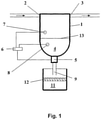
- a fuel filter is shown schematically with a housing 1 , on the upper side wall of which a fuel inlet 2 and a fuel outlet 3 are provided on opposite sides. It is well known to those skilled in the art how a filter for filtering the fuel can be arranged in a fuel filter housing and what means are to be provided for separating water. For this reason, the arrangement of the filter in the fuel filter housing and the means for separating water from the fuel were not shown for reasons of simplification.
- the lower area of the housing 1 serves as a sump 4 for water which is separated when the fuel is filtered. At the bottom of the sump 4 there is a water outlet 5 with a controllable closure. The closure is controlled via a control unit 6 as a function of the level signals from an upper water level sensor 7 and a lower water level sensor 8 .
- a vertical line 9 is arranged on the underside of the closure.
- the line 9 ends in a container 11 which is arranged below the housing 1 and is open at the top. Inside the container, an absorbent material 12 for absorbing water discharged from the sump 3 is arranged, which extends horizontally over the entire internal cavity of the container 11 .
- the absorbent material can consist, for example, at least partially of a sponge, absorbent paper or fleece.
- the closure can be designed as a valve if the pressure at the bottom of the sump is greater than the ambient pressure, so that the water can simply drain out of the sump when the valve is open. This is always the case in particular when the fuel filter is arranged behind a fuel pump in the flow direction of the fuel. If the pressure at the bottom of the sump is lower than the ambient pressure, the closure 4 must have a pump so that the water can be pumped out of the sump 4 against the pressure difference.
- valve is opened or the pump is actuated via the control unit 6 when the water level indicated by line 13 in the sump 4 of the fuel filter has reached the upper water level sensor 7 . Conversely, the valve is closed or the pump switched off via the control unit 6 when the water level 13 has reached or fallen below the lower water level sensor 8 .
- control unit 6 can determine the point in time for closing the valve or for switching off the pump using a time constant, which can be based, for example, on empirical data on the outflow speed of the water from the sump 4 . Or a clearly defined amount of water is discharged, as is possible when using a volumetric pump, for example.
- the water is drained into the container 11 where it is absorbed by the absorbent material 12. If so much water is drained from the sump 4 that it cannot be completely absorbed by the absorbent material, the excess water can drip down and be collected at the bottom of the container.
- the absorbent material 12 offers protection against the water collected on the bottom of the container 11 being splashed out, so that contamination of the environment by dirt particles or oil residues dissolved in the water is reliably avoided.
- the water With proper sizing of the absorbent material, the water is allowed to fully evaporate to the environment within the time allowed for evaporation between times that water is drained from the fuel filter sump.
- the evaporation is usually supported by an increased ambient temperature caused by the waste heat from the engine.
- FIG 2 shows a preferred circuit arrangement for controlling the water drain with an upper and a lower water level sensor. It has a voltage source 21, four switches 22, 23, 24, 25, a relay 26 and a signal transmitter 27 .
- the first switch 22 is switched by an upper water sensor, the second switch 23 by a lower water sensor.
- the third switch 24 and the fourth switch 25 are switched by the relay 26 .
- the fourth switch 25 is switched on, the signal generator 27 is connected to the voltage source, the second and third switches 23, 24 are connected in series and are parallel to the first switch 22.
- the relay 26 is connected to the voltage source 21 .
- the second switch 23 is switched on.
- the first switch 22 is switched on when the water level has reached the upper water level sensor, ie when a maximum water level has been reached or exceeded.
- the relay 26 is connected to the voltage source 21 and thereby switched.
- the third and fourth switches 24, 25 are short-circuited, so that the signal transmitter 27 is connected to the voltage source 21 and emits a signal to open the water outlet, for example to open a valve or to activate a pump, and water is drawn out of the sump of the fuel filter can drain.
- the first switch 22 open again.
- relay 26 has no effect on the switching status of relay 26, since it remains connected to voltage source 21 via second and third switches 23, 24, both of which are still closed.
- the second switch 23 is only opened again when the water level has fallen below the lower water sensor and thus the minimum water level.
- the power supply to the relay 26 is interrupted so that it switches over and the third and fourth switches 24, 25 are opened again.
- the signal generator 27 is disconnected from the voltage source 21 so that the signal level changes and the water outlet is closed.
- FIG 3 Another preferred variant of a water sensor system for determining when a maximum and a minimum water level has been reached is shown.
- the water sensor system consists of a laser 31 placed on one side of the sump 32 and directed obliquely upwards.
- the laser 31 is preferably aligned so that its beam crosses a predetermined level as the minimum water level at the center of the sump.
- two light sensors 33, 34 are arranged one above the other, with the first light sensor 33 being aligned in such a way that the laser beam reflected at the phase edge between fuel and water impinges on the sensor surface when the water level is at a minimum, and the second light sensor 34 being aligned in such a way is that the laser beam reflected at the phase edge hits its sensor surface at maximum water level.
- the other components of the fuel filter, such as the water drain, etc. are not shown for the sake of simplicity.
- Such a water sensor system is particularly suitable for fuel systems in fixed, non-moving combustion apparatus.
- FIG 4 shows the principle of a float control for opening the water outlet 41 at a maximum water level and closing the water outlet 41 at a minimum water level.
- a floating body 42 is formed so that it floats on the aqueous phase, but is heavier than the fuel, interacts with a valve pin 43 together so that it lifts the valve pin 43 when a certain maximum water level is exceeded in the sump 44, and lowers the valve pin 43 again as soon as the water level falls below a certain minimum.
- the valve pin 43 is guided through a through opening 45 in the floating body 42 .
- valve pin 43 At its upper end and in its lower region, slightly above its valve cone 46 that closes the water outlet 41, it has encircling webs 47, 48 that act as drivers and interact with corresponding recesses 49, 50 on the top and bottom of the floating body 42 . If the floating body 42 exceeds the maximum water level, the valve pin 43 is raised so that the water outlet 41 is opened. The valve pin 43 then remains in its raised position until so much water has been drained from the sump that the floating body, which is sinking with the water level, presses the valve pin 43 down so that the water outlet 41 is closed again when the minimum water level is reached . A guide mechanism for the valve pin 43 is not shown for reasons of simplification.
- FIG. 5 shows the sump 51 of a fuel filter with a water drain 52 , which can be opened and closed via an electromagnetically closable valve 53 , and to which a filter body 54 is connected, through which the water drained from the sump 51 is cleaned, see above that it can be discharged directly to the environment.
- the filter body 54 can also be designed as a sponge that holds the water so that it can evaporate to the environment. In both cases, impurities contained in the drained water remain in the filter body 54 .
- Positioning elements such as bimetals or memory metals can also be used as means for controlling the water outlet, which, for example, lift the valve cone against a spring force when the water outlet is to be opened.
- a floating body can be used, which does not interact directly with a valve pin, but with a valve pin via a lever mechanism.
- Filters for cleaning the drained or drained water can also be optionally linked to one another with a system for evaporating the then cleaned water or a system for binding impurities by means of chemicals or catalysts.
Landscapes
- Engineering & Computer Science (AREA)
- Chemical & Material Sciences (AREA)
- Combustion & Propulsion (AREA)
- Mechanical Engineering (AREA)
- General Engineering & Computer Science (AREA)
- Chemical Kinetics & Catalysis (AREA)
- Filtration Of Liquid (AREA)
- Cooling, Air Intake And Gas Exhaust, And Fuel Tank Arrangements In Propulsion Units (AREA)
Claims (16)
- Filtre à carburant, en particulier filtre à gazole, comportant au moins une entrée de carburant (2),au moins une sortie de carburant (3),des moyens pour isoler l'eau,au moins un pot (4, 32, 44, 51),une évacuation d'eau (5, 41, 52) associée au pot etdes moyens de commande (6) pour l'évacuation d'eau (5, 41, 52),avec des moyens pour séparer les impuretés de l'eau évacuée,caractérisé en ce quele filtre à carburant comporte en aval de l'évacuation d'eau, un corps de filtre (54), en particulier un filtre à charbon actif, pour filtrer l'eau évacuée du pot, le corps de filtre (54) étant réalisé en tant qu'éponge qui retient l'eau, de sorte qu'elle puisse s'évaporer dans l'environnement.
- Filtre à carburant selon la revendication 1,
caractérisé par
un filtre pour le nettoyage du carburant, le pot étant associé au côté propre du filtre. - Filtre à carburant selon la revendication 1,
caractérisé par
un filtre pour le nettoyage du carburant, le pot étant associé au côté sale du filtre. - Filtre à carburant selon l'une quelconque des revendications 1 à 3,
caractérisé par
une unité de collecte d'eau et d'évaporation ouverte sur l'environnement et placée en aval de l'évacuation d'eau (4) . - Filtre à carburant selon la revendication 4,
caractérisé en ce que
l'unité de collecte d'eau et d'évaporation présente un récipient (11) ouvert sur l'environnement dans une zone supérieure. - Filtre à carburant selon la revendication 4 ou 5,
caractérisé en ce que
l'unité de collecte d'eau et d'évaporation présente une matière absorbante (12). - Filtre à carburant selon la revendication 6,
caractérisé en ce que
la matière (12) est constituée, au moins en partie, de papier absorbant. - Filtre à carburant selon la revendication 6 ou la revendication 7,
caractérisé en ce que
la matière (12) est au moins partiellement spongieuse. - Filtre à carburant selon l'une quelconque des revendications 4 à 8,
caractérisé en ce que
l'unité de collecte d'eau et d'évaporation présente une grande surface d'évaporation. - Filtre à carburant selon l'une quelconque des revendications 1 à 9,
caractérisé par
des produits chimiques pour la liaison des impuretés qui sont prévus dans le pot et/ou dans une chambre placée en aval de l'évacuation d'eau. - Filtre à carburant selon l'une quelconque des revendications 1 à 10,
caractérisé en ce
qu'une soupape (46, 53) pouvant être commandée, est disposée sur l'évacuation d'eau (5, 41, 52). - Filtre à carburant selon l'une quelconque des revendications 1 à 11,
caractérisé par
une soupape (43, 46) actionnée par un corps flottant (42). - Filtre à carburant selon l'une quelconque des revendications 1 à 12,
caractérisé par
une pompe prévue sur l'évacuation d'eau (5). - Filtre à carburant selon la revendication 13,
caractérisé par
une pompe volumétrique. - Filtre à carburant selon l'une quelconque des revendications 1 à 14,
caractérisé par
au moins un capteur de niveau d'eau (7, 8, 33, 34) disposé dans la région du pot (4, 32, 44, 51) pour commander l'évacuation d'eau (5). - Filtre à carburant selon la revendication 15,
caractérisé par
deux capteurs de niveau d'eau (7, 8, 31, 33, 34).
Applications Claiming Priority (5)
| Application Number | Priority Date | Filing Date | Title |
|---|---|---|---|
| DE10261742 | 2002-12-30 | ||
| DE10261742 | 2002-12-30 | ||
| DE10350781A DE10350781A1 (de) | 2002-12-30 | 2003-10-30 | Kraftstofffilter |
| DE10350781 | 2003-10-30 | ||
| PCT/DE2003/003842 WO2004061289A1 (fr) | 2002-12-30 | 2003-11-20 | Filtre a carburant |
Publications (3)
| Publication Number | Publication Date |
|---|---|
| EP1581736A1 EP1581736A1 (fr) | 2005-10-05 |
| EP1581736B1 EP1581736B1 (fr) | 2007-08-08 |
| EP1581736B2 true EP1581736B2 (fr) | 2022-01-19 |
Family
ID=32602450
Family Applications (1)
| Application Number | Title | Priority Date | Filing Date |
|---|---|---|---|
| EP03776851.2A Expired - Lifetime EP1581736B2 (fr) | 2002-12-30 | 2003-11-20 | Filtre a carburant |
Country Status (2)
| Country | Link |
|---|---|
| EP (1) | EP1581736B2 (fr) |
| DE (1) | DE10350781A1 (fr) |
Families Citing this family (17)
| Publication number | Priority date | Publication date | Assignee | Title |
|---|---|---|---|---|
| DE102004048565A1 (de) * | 2004-10-04 | 2006-04-06 | Mann + Hummel Gmbh | Flüssigkeitsfilter |
| DE102004053645A1 (de) * | 2004-11-03 | 2006-05-04 | Eads Deutschland Gmbh | Vorrichtung und System zur Detektion von Wasser in Brennstofftanks von Flugzeugen sowie Wasserablassventil für Flugzeugtragflächen |
| DE202005015595U1 (de) * | 2005-09-30 | 2007-02-08 | Mann + Hummel Gmbh | Vorrichtung zur Wasserabführung aus einem Kraftstoffbehälter |
| DE202005015596U1 (de) * | 2005-09-30 | 2007-02-08 | Mann + Hummel Gmbh | Vorrichtung zur Abführung von Wasser aus einem kraftstofführenden Behälter |
| DE102006039581B4 (de) * | 2006-08-23 | 2017-07-06 | Mahle International Gmbh | Kraftstofffilter |
| DE102007039661B4 (de) * | 2006-08-23 | 2017-05-24 | Mahle International Gmbh | Kraftstofffilter |
| DE202006019301U1 (de) | 2006-12-23 | 2008-04-30 | Mann+Hummel Gmbh | Kraftstofffilter |
| DE102008020233A1 (de) | 2008-04-22 | 2009-10-29 | Hydac Filtertechnik Gmbh | Kraftstofffiltersystem, insbesondere für Dieselmotoren |
| DE102008022406A1 (de) * | 2008-05-06 | 2009-11-12 | Hengst Gmbh & Co.Kg | Verfahren und Vorrichtung zum Abscheiden von Wasser aus Kraftstoff |
| DE102008034904A1 (de) | 2008-07-26 | 2010-01-28 | Mahle International Gmbh | Moduleinsatz zum Einbau in einen Flüssigkeitsfilter |
| DE102008034903A1 (de) * | 2008-07-26 | 2010-01-28 | Mahle International Gmbh | Filtereinrichtung |
| DE102009019800A1 (de) * | 2009-05-02 | 2010-11-11 | Hydac Filtertechnik Gmbh | Vorrichtung zum Reinigen von Wasser |
| US8409446B2 (en) | 2009-08-21 | 2013-04-02 | Cummins Filtration Ip, Inc. | Automatic draining system to drain fluid from a filter |
| DE102011076413A1 (de) | 2011-05-24 | 2012-11-29 | Robert Bosch Gmbh | Kraftstofffilter mit einem Filtermedium |
| DE102011083486A1 (de) | 2011-09-27 | 2013-03-28 | Robert Bosch Gmbh | Brennstoffversorgungsvorrichtung mit einer Abscheideeinrichtung |
| DE202016104693U1 (de) | 2016-08-26 | 2016-09-07 | FAUDI Aviation GmbH | Abscheidungsvorrichtung für Fluidsammelsümpfe, insbesondere von Filter- oder Wasserabscheidern, und Fluidbehältereinrichtungen mit einer solchen |
| WO2020084627A1 (fr) * | 2018-10-22 | 2020-04-30 | Mahle Anand Filter Systems Private Limited | Dispositif de vidage d'eau |
-
2003
- 2003-10-30 DE DE10350781A patent/DE10350781A1/de not_active Withdrawn
- 2003-11-20 EP EP03776851.2A patent/EP1581736B2/fr not_active Expired - Lifetime
Also Published As
| Publication number | Publication date |
|---|---|
| DE10350781A1 (de) | 2004-07-29 |
| EP1581736B1 (fr) | 2007-08-08 |
| EP1581736A1 (fr) | 2005-10-05 |
Similar Documents
| Publication | Publication Date | Title |
|---|---|---|
| EP1581736B2 (fr) | Filtre a carburant | |
| WO2004061289A1 (fr) | Filtre a carburant | |
| DE60026724T2 (de) | Vorrichtung zur automatischen wasserabscheidung in einem fahrzeugbrennstofffilter, insbesondere für dieselbrennkraftmaschinen | |
| EP2574388B1 (fr) | Filtre à carburant | |
| DE68927589T2 (de) | Vakuumtoilettensystem | |
| EP1690789B1 (fr) | Aéronef avec système pour l'utilisation des eaux usées | |
| DE2312571A1 (de) | Verfahren zum reinigen von mit spezifisch leichteren fluessigkeiten sowie vorrichtung zur durchfuehrung des verfahrens | |
| DE2848660A1 (de) | Filtriervorrichtung | |
| DE102004032251B4 (de) | Vorrichtung zur Abscheidung von Wasser und zur Ausfilterung von Verunreinigungen | |
| EP2221097A1 (fr) | Dispositif de filtre destiné à l'adsorption d'hydrocarbures | |
| EP1588044B1 (fr) | Unite d'evaporation pour un filtre a carburant | |
| DE2743530C3 (de) | Vorrichtung zum Reinigen von großflächigen TextUauflagen, insbesondere von Teppichen und Teppichboden | |
| EP1131550A1 (fr) | Filtre a air destine a filtrer l'air d'aspiration de moteurs a combustion interne de vehicules automobiles | |
| DE69933803T2 (de) | Verfahren und Einrichtung zur Steuerung der Reinigung von einem Lüftungsrost | |
| DE19541950A1 (de) | Entsorgungsfahrzeug | |
| EP2752317B1 (fr) | Véhicule automobile doté d'une boîte d'eau et d'un appareil de climatisation | |
| DE19718451C2 (de) | Scheibenwaschvorrichtung | |
| DE202007012990U1 (de) | Luftreinigungsvorrichtung für Fahrzeuge | |
| DE69305685T2 (de) | Filter zum Waschen und Festhalten der Abgase von Kraftfahrzeugen | |
| DE102004061874B4 (de) | Kraftstoffpumpenmodul | |
| DE19730188A1 (de) | Vorrichtung zum Vermeiden des Wassereintritts in ein Luftfiltergehäuse einer Brennkraftmaschine | |
| EP3516201A2 (fr) | Procédé de déshumidification d'un consommable, dispositif de déshumidification ainsi que dispositif d'alimentation en consommable | |
| DE19719563B4 (de) | Kühlanlage | |
| DE10316652A1 (de) | Luftfilter für eine Brennkraftmaschine | |
| DE9313840U1 (de) | Aktivkohlefilter für Kraftfahrzeuge |
Legal Events
| Date | Code | Title | Description |
|---|---|---|---|
| PUAI | Public reference made under article 153(3) epc to a published international application that has entered the european phase |
Free format text: ORIGINAL CODE: 0009012 |
|
| 17P | Request for examination filed |
Effective date: 20050801 |
|
| AK | Designated contracting states |
Kind code of ref document: A1 Designated state(s): AT BE BG CH CY CZ DE DK EE ES FI FR GB GR HU IE IT LI LU MC NL PT RO SE SI SK TR |
|
| RBV | Designated contracting states (corrected) |
Designated state(s): DE FR IT |
|
| 17Q | First examination report despatched |
Effective date: 20060317 |
|
| GRAP | Despatch of communication of intention to grant a patent |
Free format text: ORIGINAL CODE: EPIDOSNIGR1 |
|
| GRAS | Grant fee paid |
Free format text: ORIGINAL CODE: EPIDOSNIGR3 |
|
| GRAA | (expected) grant |
Free format text: ORIGINAL CODE: 0009210 |
|
| AK | Designated contracting states |
Kind code of ref document: B1 Designated state(s): DE FR IT |
|
| REF | Corresponds to: |
Ref document number: 50307913 Country of ref document: DE Date of ref document: 20070920 Kind code of ref document: P |
|
| ET | Fr: translation filed | ||
| PLBI | Opposition filed |
Free format text: ORIGINAL CODE: 0009260 |
|
| PLBI | Opposition filed |
Free format text: ORIGINAL CODE: 0009260 |
|
| 26 | Opposition filed |
Opponent name: MAHLE INTERNATIONAL GMBH Effective date: 20080507 Opponent name: HYDAC FILTERTECHNIK GMBH Effective date: 20080502 |
|
| PLAX | Notice of opposition and request to file observation + time limit sent |
Free format text: ORIGINAL CODE: EPIDOSNOBS2 |
|
| 26 | Opposition filed |
Opponent name: MANN + HUMMEL GMBH Effective date: 20080508 Opponent name: MAHLE INTERNATIONAL GMBH Effective date: 20080507 Opponent name: HYDAC FILTERTECHNIK GMBH Effective date: 20080502 |
|
| PLAF | Information modified related to communication of a notice of opposition and request to file observations + time limit |
Free format text: ORIGINAL CODE: EPIDOSCOBS2 |
|
| PLBB | Reply of patent proprietor to notice(s) of opposition received |
Free format text: ORIGINAL CODE: EPIDOSNOBS3 |
|
| REG | Reference to a national code |
Ref country code: FR Ref legal event code: PLFP Year of fee payment: 13 |
|
| APAH | Appeal reference modified |
Free format text: ORIGINAL CODE: EPIDOSCREFNO |
|
| APBM | Appeal reference recorded |
Free format text: ORIGINAL CODE: EPIDOSNREFNO |
|
| APBP | Date of receipt of notice of appeal recorded |
Free format text: ORIGINAL CODE: EPIDOSNNOA2O |
|
| APBM | Appeal reference recorded |
Free format text: ORIGINAL CODE: EPIDOSNREFNO |
|
| APBP | Date of receipt of notice of appeal recorded |
Free format text: ORIGINAL CODE: EPIDOSNNOA2O |
|
| APBQ | Date of receipt of statement of grounds of appeal recorded |
Free format text: ORIGINAL CODE: EPIDOSNNOA3O |
|
| APBQ | Date of receipt of statement of grounds of appeal recorded |
Free format text: ORIGINAL CODE: EPIDOSNNOA3O |
|
| PLAB | Opposition data, opponent's data or that of the opponent's representative modified |
Free format text: ORIGINAL CODE: 0009299OPPO |
|
| PLAB | Opposition data, opponent's data or that of the opponent's representative modified |
Free format text: ORIGINAL CODE: 0009299OPPO |
|
| R26 | Opposition filed (corrected) |
Opponent name: MANN + HUMMEL GMBH Effective date: 20080508 |
|
| R26 | Opposition filed (corrected) |
Opponent name: MAHLE INTERNATIONAL GMBH Effective date: 20080507 |
|
| REG | Reference to a national code |
Ref country code: FR Ref legal event code: PLFP Year of fee payment: 14 |
|
| REG | Reference to a national code |
Ref country code: FR Ref legal event code: PLFP Year of fee payment: 15 |
|
| PLAB | Opposition data, opponent's data or that of the opponent's representative modified |
Free format text: ORIGINAL CODE: 0009299OPPO |
|
| R26 | Opposition filed (corrected) |
Opponent name: HYDAC FILTERTECHNIK GMBH Effective date: 20080502 |
|
| APBU | Appeal procedure closed |
Free format text: ORIGINAL CODE: EPIDOSNNOA9O |
|
| RAP2 | Party data changed (patent owner data changed or rights of a patent transferred) |
Owner name: ROBERT BOSCH GMBH |
|
| RIC2 | Information provided on ipc code assigned after grant |
Ipc: F02M 37/22 20190101AFI20210409BHEP Ipc: B01D 17/02 20060101ALI20210409BHEP Ipc: F02M 37/28 20190101ALI20210409BHEP Ipc: F02M 37/32 20190101ALI20210409BHEP Ipc: B01D 36/00 20060101ALI20210409BHEP |
|
| APAH | Appeal reference modified |
Free format text: ORIGINAL CODE: EPIDOSCREFNO |
|
| APBM | Appeal reference recorded |
Free format text: ORIGINAL CODE: EPIDOSNREFNO |
|
| APBP | Date of receipt of notice of appeal recorded |
Free format text: ORIGINAL CODE: EPIDOSNNOA2O |
|
| APBU | Appeal procedure closed |
Free format text: ORIGINAL CODE: EPIDOSNNOA9O |
|
| PUAH | Patent maintained in amended form |
Free format text: ORIGINAL CODE: 0009272 |
|
| STAA | Information on the status of an ep patent application or granted ep patent |
Free format text: STATUS: PATENT MAINTAINED AS AMENDED |
|
| 27A | Patent maintained in amended form |
Effective date: 20220119 |
|
| AK | Designated contracting states |
Kind code of ref document: B2 Designated state(s): DE FR IT |
|
| REG | Reference to a national code |
Ref country code: DE Ref legal event code: R102 Ref document number: 50307913 Country of ref document: DE |
|
| PGFP | Annual fee paid to national office [announced via postgrant information from national office to epo] |
Ref country code: IT Payment date: 20221130 Year of fee payment: 20 Ref country code: FR Payment date: 20221118 Year of fee payment: 20 |
|
| PGFP | Annual fee paid to national office [announced via postgrant information from national office to epo] |
Ref country code: DE Payment date: 20230124 Year of fee payment: 20 |
|
| REG | Reference to a national code |
Ref country code: DE Ref legal event code: R071 Ref document number: 50307913 Country of ref document: DE |