EP1581883B1 - System und verfahren zur messung der middelware-ansprechzeit - Google Patents
System und verfahren zur messung der middelware-ansprechzeit Download PDFInfo
- Publication number
- EP1581883B1 EP1581883B1 EP03800423A EP03800423A EP1581883B1 EP 1581883 B1 EP1581883 B1 EP 1581883B1 EP 03800423 A EP03800423 A EP 03800423A EP 03800423 A EP03800423 A EP 03800423A EP 1581883 B1 EP1581883 B1 EP 1581883B1
- Authority
- EP
- European Patent Office
- Prior art keywords
- queue
- time
- message
- route
- determining
- Prior art date
- Legal status (The legal status is an assumption and is not a legal conclusion. Google has not performed a legal analysis and makes no representation as to the accuracy of the status listed.)
- Expired - Lifetime
Links
Images





Classifications
-
- H—ELECTRICITY
- H04—ELECTRIC COMMUNICATION TECHNIQUE
- H04L—TRANSMISSION OF DIGITAL INFORMATION, e.g. TELEGRAPHIC COMMUNICATION
- H04L43/00—Arrangements for monitoring or testing data switching networks
- H04L43/06—Generation of reports
- H04L43/062—Generation of reports related to network traffic
-
- G—PHYSICS
- G06—COMPUTING OR CALCULATING; COUNTING
- G06F—ELECTRIC DIGITAL DATA PROCESSING
- G06F15/00—Digital computers in general; Data processing equipment in general
- G06F15/16—Combinations of two or more digital computers each having at least an arithmetic unit, a program unit and a register, e.g. for a simultaneous processing of several programs
-
- G—PHYSICS
- G06—COMPUTING OR CALCULATING; COUNTING
- G06F—ELECTRIC DIGITAL DATA PROCESSING
- G06F11/00—Error detection; Error correction; Monitoring
- G06F11/30—Monitoring
-
- H—ELECTRICITY
- H04—ELECTRIC COMMUNICATION TECHNIQUE
- H04L—TRANSMISSION OF DIGITAL INFORMATION, e.g. TELEGRAPHIC COMMUNICATION
- H04L43/00—Arrangements for monitoring or testing data switching networks
- H04L43/08—Monitoring or testing based on specific metrics, e.g. QoS, energy consumption or environmental parameters
- H04L43/0852—Delays
-
- H—ELECTRICITY
- H04—ELECTRIC COMMUNICATION TECHNIQUE
- H04L—TRANSMISSION OF DIGITAL INFORMATION, e.g. TELEGRAPHIC COMMUNICATION
- H04L47/00—Traffic control in data switching networks
- H04L47/10—Flow control; Congestion control
- H04L47/28—Flow control; Congestion control in relation to timing considerations
- H04L47/283—Flow control; Congestion control in relation to timing considerations in response to processing delays, e.g. caused by jitter or round trip time [RTT]
-
- H—ELECTRICITY
- H04—ELECTRIC COMMUNICATION TECHNIQUE
- H04L—TRANSMISSION OF DIGITAL INFORMATION, e.g. TELEGRAPHIC COMMUNICATION
- H04L41/00—Arrangements for maintenance, administration or management of data switching networks, e.g. of packet switching networks
- H04L41/22—Arrangements for maintenance, administration or management of data switching networks, e.g. of packet switching networks comprising specially adapted graphical user interfaces [GUI]
-
- H—ELECTRICITY
- H04—ELECTRIC COMMUNICATION TECHNIQUE
- H04L—TRANSMISSION OF DIGITAL INFORMATION, e.g. TELEGRAPHIC COMMUNICATION
- H04L43/00—Arrangements for monitoring or testing data switching networks
- H04L43/04—Processing captured monitoring data, e.g. for logfile generation
- H04L43/045—Processing captured monitoring data, e.g. for logfile generation for graphical visualisation of monitoring data
-
- H—ELECTRICITY
- H04—ELECTRIC COMMUNICATION TECHNIQUE
- H04L—TRANSMISSION OF DIGITAL INFORMATION, e.g. TELEGRAPHIC COMMUNICATION
- H04L43/00—Arrangements for monitoring or testing data switching networks
- H04L43/10—Active monitoring, e.g. heartbeat, ping or trace-route
- H04L43/106—Active monitoring, e.g. heartbeat, ping or trace-route using time related information in packets, e.g. by adding timestamps
-
- H—ELECTRICITY
- H04—ELECTRIC COMMUNICATION TECHNIQUE
- H04L—TRANSMISSION OF DIGITAL INFORMATION, e.g. TELEGRAPHIC COMMUNICATION
- H04L43/00—Arrangements for monitoring or testing data switching networks
- H04L43/16—Threshold monitoring
Definitions
- the present application relates to message oriented middleware performance monitoring and, more particularly, to a system and a method for measuring middleware response time.
- middleware is software that has its own application programming interfaces ("APIs") that help insulate software developers from operating system-specific APIs.
- APIs application programming interfaces
- a middleware layer is often located between client and server processes.
- problems can be identified and corrected resulting in improved performance and availability.
- the route time associated with a middleware application can be measured by changing the code of the application itself. Such a procedure is considered intrusive.
- Other known procedures used for measuring route time rely on a host of resources and require synchronization among multiple components.
- the application also provides for a method for monitoring middleware performance.
- the method may include determining a route time for a message transmitted along a predetermined network route, determining at least one queue residency time, the at least one queue residency time reflecting an amount of time at least one other message is stored in at least one respective queue located along the predetermined network route, and calculating a middleware response time according to the route time and the at least one queue residency time.
- the application further provides for a method for monitoring middleware performance.
- the method may include determining a route time for a user-defined sample message to be transmitted along a predetermined network route, the route time reflecting an amount of time for the sample message to travel from an origination queue manager to a destination queue manager and then back along the same route to the origination queue manager, determining at least one queue residency time for at least one local production queue, the at least one local production queue being associated with the origination queue manager and/or the destination queue manager and the at least one queue residency time reflecting the amount of time an actual application message is stored in the at least one local production queue, and calculating a middleware response time by adding the route time to the at least one queue residency time.
- the application further provides for a system for monitoring middleware performance.
- the system may include a computer system adapted to generate a sample message and an application message, and a computer memory electrically connected to the computer system encoded with instructions for performing the following: determining a route time for the sample message transmitted along a predetermined network route; determining at least one queue residency time, the at least one queue residency time reflecting an amount of time the application message is stored in at least one respective queue located along the predetermined network route; and calculating a middleware response time according to the route time and the at least one queue residency time.
- application middleware response time for a message oriented middleware (“MOM”) based application can be estimated without changes to the respective application(s) and is, therefore, non-intrusive, as described herein.
- MOM message oriented middleware
- An example of such a MOM based application is the e-business infrastructure software sold by IBM® under the label WebSphere® MQ.
- WebSphere® MQ is a middleware solution for interconnecting business applications in heterogeneous environments.
- Middleware response time is described in the present application as being comprised of two components: route time and the sum of each of the storage residency times. Even though storage residency time is referred to in the present application as queue residency time, the exemplary embodiments are equally applicable to additional storage mediums besides queues.
- application processing time is not considered in determining the middleware response time as described in detail herein. Alternatively, however, processing time can be included in the response time determination.
- FIG. 1 illustrates an exemplary MOM network 100.
- MOM network 100 includes three exemplary queue managers ("Qmgr") or MOM controllers, referred to herein as queue managers: queue manager 105a, queue manager 105b and queue manager 105c.
- Queue managers 105a, 105b, 105c are associated with node A 150a, node B 150b, node C 150c and local production queues 110a, 110b, 110c, respectively.
- queue managers 105a, 105b, 105c are associated with agents 115, 125, 130 and transmission queues 120a, 120b, 120c, respectively.
- the number of queue managers in MOM network 100 and the number and type of queues associated with the respective queue managers are merely illustrative.
- Data can be transmitted from node A 150a, node B 150b and node C 150c to collection point 130.
- Collection point 130 includes memory unit 140 and processing unit 145.
- Each transmission queue is associated with a corresponding remote queue definition, as can be seen in Fig. 1 .
- Remote queue definitions are not real queues, but name aliases that are controlled as though they were real queues. An effect of the remote queue definition is to define a physical destination queue name and queue manager name. The use of remote queue definitions is well known to a person having ordinary skill in the art and is therefore not described in detail herein.
- a sample message is transmitted from and to queue manager 105a along the same path or network route in MOM network 100 as would be used by an application to be monitored and the sample message is temporarily stored in each transmission queue 120a, 120b, 120c along the network route.
- the sample message is used to determine the route time.
- an actual application message is stored at each local production queue 110a, 110b, 110c to determine the respective queue residency times.
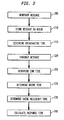
- FIG. 2 illustrates an exemplary flow diagram for estimating an application middleware response time of a MOM application.
- the route time and at least one queue residency time need to be determined.
- a sample message is generated, in 205.
- the sample message includes a plurality of messages batched together.
- the size of each of the plurality of messages can be the same or have varying sizes.
- the sample message is a single message.
- the sample message replicates an actual message that would be transmitted within MOM network 100.
- the number of messages batched in a sample message and the size of each of the messages is user-controlled, for instance, by interacting with at least one user interface.
- the sample message is stored, in 210.
- Agent 115 associated with queue manager 105a puts the sample message in transmission queue 120a.
- Transmission queue 120a temporarily stores the sample message to be sent to another part of the application residing on queue manager 105b.
- Remote queue definition associated with transmission queue 120a points to or identifies queue manager 105b and, more particularly, transmission queue 120b and its associated remote queue definition.
- the originating time is determined by agent 115, in 215.
- the originating time is stored in field 505 of sample message 500, as shown in Fig. 5 , and the sample message is transmitted within MOM network 100, in 220.
- Figure 4 sets forth in more detail the transmission of the sample message and the determination of at least one arrive time and at least sent time along the route.
- the sample message is transmitted from originating queue manager 105a to destination queue manager 105c via intervening queue manager 105b. Specifically, the sample message is first transmitted to and temporally stored in transmission queue 120b since remote queue definition associated with transmission queue 120a points to transmission queue 120b.
- channel or message exits associated with agent 125 determine timestamps for when the sample message enters transmission queue 120b and exits transmission queue 120b, referred to as the arrive time and the sent time, respectively, in 410.
- the arrive time and the sent time are added to the sample message in field 510a and field 510b, respectively, as shown in Fig. 5 .
- the application component on queue manager 105b associated with agent 125 retrieves the sample message temporarily stored in transmission queue 120b and according to the respective remote queue definition transmits the sample message to another application component on destination queue manager 105c.
- the sample message is temporarily stored in transmission queue 120c.
- channel or message exits associated with agent 130 determine timestamps for when the sample message enters transmission queue 120c and exits transmission queue 120c, referred to as the arrive time and the sent time, respectively, in 410.
- the arrive time and the sent time are added to the sample message in field 515a and field 515b, respectively, as shown in Fig. 5 .
- the application component on queue manager 105c associated with agent 130 retrieves the message temporarily stored in transmission queue 120c and according to the respective remote queue definition transmits the sample message back to originating queue manager 105a via intervening queue manager 105b, in 415.
- the sample message is transmitted back to originating queue manager 105a along the same route that the sample message traveled to get to destination queue manager 105c, a purpose of which is described below.
- the exemplary route of the sample message is shown in Fig. 3 .
- Alternative routes for sample messages are also described below.
- an arrive time and a sent time for the sample message are determined for intervening queue manager 105b.
- agent 115 determines an end time, in 225, and the end time is stored in field 525 of the sample message. In an exemplary embodiment, agent 115 determines that the sample message transmitted from queue manager 105a is the same as the received message by comparing an identification stored in a field of each received message.
- Route time is defined as the time it takes a sample message to be transmitted from the queue manager where the message originated, for instance, queue managers 105a, across any intermediate queue manager(s), to a destination queue manager, for instance, queue manager 105c, and have the message transmitted back to the originating queue manager from the destination queue manager 105c along the same route.
- measurement of route time relies on an independent process that sends sample messages through MOM network 100 using the same paths as the application to be measured.
- the route time component is measured by creating a series of daisy-chained remote queue definitions across all queue managers involved in the measurement, for example, queue managers 105a, 105b, 105c.
- processing unit 145 determines the route time, in 230. Specifically, the route time is determined by taking the difference of the originating timestamp and the end timestamp. Since the originating timestamp and the end timestamp are associated with the same queue manager. 105a, synchronization is not an issue.
- the route time is stored in memory unit 140 at collection point 135.
- intra-queue manager times are determined by processing unit 145.
- the difference between the arrive timestamp and the corresponding sent timestamp for a respective queue manager represents the intra-queue manager time.
- the sum of the intra-queue manager times along MOM network 100 represents the total queue manager processing time.
- averages of the intra-queue manager times along MOM network 100 can also be calculated.
- Data representing the intra-queue manager times is also stored in memory unit 140.
- queue residency time is also needed for calculating the middleware response time, in 235.
- Figs. 6 and 7 illustrate queue residency time and how it is determined in an exemplary embodiment of the present application.
- Queue residency time is defined as the time that an actual application message is stored in local production queue 110a, in local production queue 110b and in local production queue 110c, as shown in Fig. 6 .
- the sum of the queue residency times is referred to as the total queue residency time.
- measurement of queue residency times relies on an independent process in which respective agents sample actual application messages being put on respective local production queues, identifies the sampled message through a channel message exit and captures the point when that message is pulled from the local production queue.
- messages are sampled at an adjustable rate. Based on the sample set of messages, queue residency time is calculated as described below with reference to Fig. 7 .
- Agents 115, 125, 130 determine queue residency time for local production queues 110a, 110b, 110c, respectively. The procedure for calculating queue residency time is described herein only with reference to agent 115 and local production queue 110a since the same procedure is followed at node B 150b and node C 150c in MOM network 100.
- collection components such as a message exit and an API exit take at least one sample of the messages, in 705.
- Agent 115 determines and stores the identification (“ID") associated with the sampled message, in 710, and determines and stores the put timestamp, in 715 and 720, respectively. The put timestamp indicates the time that the sampled message was placed on local production queue 110a.
- ID identification
- the put timestamp indicates the time that the sampled message was placed on local production queue 110a.
- the ID is located in a field of the sampled message.
- a comparison is performed between the IDs of the respective retrieved messages and the stored ID of the sampled message, in 725. If a positive match is made, another timestamp, referred to as the get timestamp, is determined, in 730.
- the get timestamp indicates the time the sampled message was retrieved from local production queue 110a.
- the queue residency time for local production queue 110a is then determined by agent 115, in 735. In an exemplary embodiment, the queue residency time equals the difference between the respective get timestamp and the respective put timestamp.
- the calculated queue residency time is transmitted to collection point 135, in 740.
- each queue manager 105a, 105b, 105c are transmitted to collection point 135.
- Processing unit 145 adds the queue residency times to determine the total queue residency time and stores the individual queue residency times and the total queue residency time in memory unit 140.
- each agent calculates respective queue residency times by sampling multiple messages stored in the queue, determining corresponding put timestamps and get timestamps for the sampled messages, calculate multiple queue residency times and average the queue residency times over an interval.
- queue managers 105a, 105b, 105c in MOM network 100 do not have to be synchronized since the difference(s) between the put timestamp(s) for a sampled message(s) and the get timestamp(s) for the sampled message(s) are determined for a respective local production queue.
- the estimated application middleware response time consisting of the time for the sample message to travel through the middleware network, referred to as the route time, and the time sampled messages reside in local production queues 110a, 110b, 110c, is determined, in 240.
- the response time is then determined by combining the route time with the sum of queue residency times. Additionally, a network time can be determined by subtracting from the route time the total intra-queue manager time.
- the exemplary embodiments of the present application for determining route time are described with reference to chained transmission queues that are kept independent from local production queues. By using transmission queues, the performance of actual application messages being transmitted over MOM network 100 is simulated. The exemplary embodiments, however, are equally applicable to using local production queues and/or actual application messages to determine route time and, thus, response time.
- queue statistics include average queue residency times, high and low queue residency times, number of get timestamps and the number of put timestamps.
- thresholds can be set to generate alerts so that, for example, when a queue residency time is greater than a threshold, an alert is transmitted for the respective queue.
- one or more user interfaces can be developed so that the performance of MOM network 100 can be monitored.
- a user can monitor the response time, queues residency time(s) and route time, whether these times are within predetermined parameters or exceed a threshold, the number of messages in the sample message and the size of each message.
- a user interface can be developed and used to monitor the performance of one or more queues.
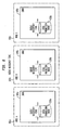
- Figure 8b illustrates an exemplary user interface for monitoring at least one queue of the present application. Further, Fig. 7b illustrates an exemplary user interface for monitoring route time of the present application.
- the user interface can include list of all the queues, status of each queue and thresholds and current value for each metric. The desired parameters and thresholds can by input by the user via one or more additional user interfaces.
- Figure 7a illustrates an exemplary user interface used by an agent for developing a route that a sample message will travel and Fig. 8a illustrates an exemplary user interface for adding a queue threshold for a particular queue.
- a route builder application is used for defining the path for the sample message.
- each route is named and the individual queue managers are added.
- the sample message is transmitted from originating queue manager 105a to destination queue manager 105c via intervening queue manager 105b and back to originating queue manager 105a along the exact same path, as shown in Fig. 3 . Accordingly, originating queue manager 105a, intervening queue manager 105b and destination queue manager 105c do not have to be synchronized to determine route time. Alternatively, by changing the remote queue definition associated with destination queue manager 105c, the sample message can travel a different path back to originating queue manager 105a.
- the queue managers do not need to be synchronized. However, if the sample message is returned to a queue manager other than originating queue manager 105a, that queue manager and originating queue manager 105a need to be synchronized to determine the route time.
- a unidirectional route time can be determined, that is the time for the sample message to travel from originating queue manager 105a to destination queue manager 105c. Originating queue manager 105a and destination queue manager 105c would need to be synchronized to accurately estimate the route time. Data is collected at collection point 135 from the respective queue managers and route time is determined by processing unit 145.
Landscapes
- Engineering & Computer Science (AREA)
- Signal Processing (AREA)
- Computer Networks & Wireless Communication (AREA)
- Theoretical Computer Science (AREA)
- General Physics & Mathematics (AREA)
- General Engineering & Computer Science (AREA)
- Computer Hardware Design (AREA)
- Physics & Mathematics (AREA)
- Environmental & Geological Engineering (AREA)
- Software Systems (AREA)
- Quality & Reliability (AREA)
- Computer And Data Communications (AREA)
- Debugging And Monitoring (AREA)
- Data Exchanges In Wide-Area Networks (AREA)
- Arrangements For Transmission Of Measured Signals (AREA)
- Management, Administration, Business Operations System, And Electronic Commerce (AREA)
Claims (17)
- Verfahren zur Überwachung der Middleware-Leistung, wobei das Verfahren umfasst:Bestimmen (230) einer Wegezeit einer Nachricht (500), die entlang eines vorbestimmten Netzwerkweges übertragen wird;Bestimmen (235) mindestens einer Speicherverweildauer, wobei die mindestens eine Speicherverweildauer eine Zeitdauer darstellt, die mindestens eine andere Nachricht (500) in mindestens einem entsprechenden Speicher gespeichert wird, der sich entlang des vorbestimmten Netzwerkweges befindet; undBerechnen (240) einer Middleware-Ansprechzeit entsprechend der Wegezeit und der mindestens einen Speicherverweildauer.
- Verfahren nach Anspruch 1, wobei der mindestens eine Speicher mindestens eine Warteschlange (110a - 110c) umfasst und die mindestens eine Speicherverweildauer mindestens eine Warteschlangenverweildauer umfasst.
- Verfahren nach Anspruch 1 oder 2, wobei das Bestimmen (230) der Wegezeit das Bestimmen einer Zeitdauer beinhaltet, welche die Nachricht (500) benötigt, um von einem Quellknoten (A 150a) entlang des vorbestimmten Netzwerkweges zu einem Zielknoten (C 150c) und anschließend zum Quellknoten (A 150a) zurückzuwandern.
- Verfahren nach Anspruch 3, wobei das Bestimmen (230) der Wegezeit beinhaltet:Bestimmen (215) eines Ausgangszeitstempels, der anzeigt, wann die Nachricht (500) vom Quellknoten (A 150a) gesendet wurde,Speichern des Ausgangszeitstempels in einem Feld (505) der Nachricht (500),Bestimmen (225) eines Endzeitstempels, der anzeigt, wann der Quellknoten (A 150a) die Nachricht (500) vom Zielknoten (C 150c) empfängt,Speichern des Endzeitstempels in einem anderen Feld (510) der Nachricht (500), undBerechnen (230) der Wegezeit durch Bestimmen der Differenz zwischen dem Ausgangszeitstempel und dem Endzeitstempel.
- Verfahren nach Anspruch 2, wobei das Bestimmen (235) der mindestens einen Warteschlangenverweildauer beinhaltet:Abtasten (705) einer Vielzahl von Anwendungsnachrichten,Bestimmen (710) einer Identifikation für die abgetastete Nachricht, wobei die Identifikation in einem Feld der abgetasteten Nachricht gespeichert wird,Speichern (710) der Identifikation der abgetasteten Nachricht,Bestimmen (715) eines Platzierungszeitstempels für die abgetastete Nachricht, wobei der Platzierungszeitstempel angibt, wann die abgetastete Nachricht in eine lokale Produktionswarteschlange (110a, 110b, 110c) platziert wurde,Vergleichen (725) der zu den Nachrichten gehörenden Identifikationen, die aus der lokalen Produktionswarteschlange (110a, 110b, 110c) abgerufen wurden, mit der Identifikation der abgetasteten Nachricht,Bestimmen (730) eines Abrufzeitstempels für die abgetastete Nachricht, wenn eine Übereinstimmung festgestellt wurde, wobei der Abrufzeitstempel angibt, wann die abgetastete Nachricht aus der lokalen Produktionswarteschlange (11, 110b, 110c) abgerufen wurde,Berechnen (735) einer Warteschlangenverweildauer durch Bestimmen der Differenz zwischen dem Platzierungszeitstempel und dem Abrufzeitstempel.
- Verfahren nach Anspruch 2, wobei das Berechnen (240) der Middleware-Ansprechzeit das Hinzufügen der Wegezeit und der mindestens einen Warteschlangenverweildauer beinhaltet.
- Verfahren nach Anspruch 2, wobei die Nachricht eine benutzerdefinierte Abtastnachricht (500) ist, die eine tatsächliche Anwendungsnachricht reproduziert.
- Verfahren nach Anspruch 7, wobei die benutzerdefinierte Abtastnachricht eine Vielzahl von gestapelten Nachrichten ist, und die Vielzahl von Nachrichten dieselbe oder eine variierende Größe aufweist.
- Verfahren nach Anspruch 2, wobei:die Wegezeit eine Zeitdauer darstellt, die eine Abtastnachricht benötigt, um von einem Ausgangswarteschlangenmanager (105a) zu einem Zielwarteschlangenmanager (105c) und denselben Weg zurück zum Ausgangswarteschlangenmanager (105a) zurückzulegen;die mindestens eine Warteschlangenverweildauer für mindestens eine lokale Produktionswarteschlange (110a - 110c) bestimmt wird, wobei die mindestens eine lokale Produktionswarteschlange (110a - 110c) mit dem Ausgangswarteschlangenmanager (105a) und/oder dem Zielwarteschlangenmanager (105c) in Verbindung steht und die mindestens eine Warteschlangenverweildauer die Zeitdauer darstellt, die eine tatsächliche Anwendungsmeldung in der mindestens einen lokalen Produktionswarteschlange (110a - 110c) gespeichert wird; unddie Middleware-Ansprechzeit berechnet wird, indem die Wegezeit zu der mindestens einen Warteschlangenverweildauer hinzugefügt wird.
- Verfahren nach Anspruch 2, wobei der vorbestimmte Netzwerkweg mithilfe einer oder mehrerer ferner Warteschlangendefinitionen definiert wird.
- Verfahren nach Anspruch 10, wobei das Verwenden einer oder mehrerer ferner Wartschlangendefinitionen zum Definieren eines vorbestimmten Netzwerkweges die Verwendung der einen oder mehreren fernen Warteschlangendefinitionen zum Identifizieren des einen oder der mehreren Knoten entlang des vorbestimmten Netzwerkweges umfasst.
- Verfahren nach Anspruch 11, wobei:jeder Knoten entlang des vorbestimmten Netzwerkweges mit mindestens einer der einen oder mehreren fernen Warteschlangendefinitionen verbunden ist; undjede der einen oder mehreren fernen Warteschlangendefinitionen einen nächsten Knoten entlang des vorbestimmten Netzwerkweges identifiziert.
- Verfahren nach Anspruch 2, ferner umfassend:Bestimmen einer Netzwerkzeit, indem von der Wegezeit eine oder mehrere Intra-Warteschlangenmanagerzeiten subtrahiert werden, die mit der mindestens einen entsprechenden Warteschlange verbunden sind, welche sich entlang des vorbestimmten Netzwerkweges befindet.
- Verfahren nach Anspruch 4, wobei:die Nachricht (500) eine Abtastnachricht umfasst;der Quellknoten (A 150a) eine erste Übertragungswarteschlange (120a) umfasst;der Zielknoten (C 150c) eine zweite Übertragungswarteschlange (120c) umfasst;das Bestimmen (235) der mindestens einen Warteschlangenverweildauer umfasst:Abtasten einer ersten Vielzahl von Anwendungsnachrichten, die in einer ersten lokalen Produktionswarteschlange (110a) gespeichert sind;Abtasten einer zweiten Vielzahl von Anwendungsnachrichten, die in einer zweiten lokalen Produktionswarteschlange (110c) gespeichert sind;die erste Übertragungswarteschlange (120a) und die zweite Übertragungswarteschlange (120c) entsprechend mit der ersten lokalen Produktionswarteschlange (110a) und der zweiten lokalen Produktionswarteschlange (110c) verbunden sind.
- Verfahren nach Anspruch 2, ferner umfassend:Erzeugen eines Alarms, der entsprechend mit der mindestens einen entsprechenden Warteschlange verbunden ist, wobei der Alarm von einer oder mehreren Warteschlangenstatistiken der mindestens einen entsprechenden Warteschlange definiert wird; undAuslösen des Alarms, wenn die eine oder mehreren Warteschlangenstatistiken vorbestimmte Schwellenwerte übersteigen.
- System zur Überwachung der Middleware-Leistung, wobei das System umfasst:Mittel zum Bestimmen (230) einer Wegezeit einer Nachricht (500), die entlang eines vorbestimmten Netzwerkweges übertragen wird;Mittel zum Bestimmen (235) mindestens einer Speicherverweildauer, wobei die mindestens eine Speicherverweildauer eine Zeitdauer darstellt, die mindestens eine andere Nachricht (500) in mindestens einem entsprechenden Speicher gespeichert wird, der sich entlang des vorbestimmten Netzwerkweges befindet; undMittel zum Berechnen (240) einer Middleware-Ansprechzeit entsprechend der Wegezeit und der mindestens einen Verweildauer im Speicher.
- Computerlesbares Medium, das Anweisungen umfasst, die bei Ausführung durch ein Computersystem die Durchführung der Schritte nach einem der Ansprüche 1 bis 15 zur Folge hat.
Applications Claiming Priority (3)
| Application Number | Priority Date | Filing Date | Title |
|---|---|---|---|
| US43784803P | 2003-01-03 | 2003-01-03 | |
| US437848P | 2003-01-03 | ||
| PCT/US2003/041786 WO2004063858A2 (en) | 2003-01-03 | 2003-12-30 | System and method for measuring middleware response time |
Publications (3)
| Publication Number | Publication Date |
|---|---|
| EP1581883A2 EP1581883A2 (de) | 2005-10-05 |
| EP1581883A4 EP1581883A4 (de) | 2009-01-07 |
| EP1581883B1 true EP1581883B1 (de) | 2010-04-21 |
Family
ID=32713239
Family Applications (1)
| Application Number | Title | Priority Date | Filing Date |
|---|---|---|---|
| EP03800423A Expired - Lifetime EP1581883B1 (de) | 2003-01-03 | 2003-12-30 | System und verfahren zur messung der middelware-ansprechzeit |
Country Status (11)
| Country | Link |
|---|---|
| US (1) | US7386613B2 (de) |
| EP (1) | EP1581883B1 (de) |
| JP (1) | JP2006512687A (de) |
| KR (1) | KR20050084519A (de) |
| CN (1) | CN1833235A (de) |
| AT (1) | ATE465454T1 (de) |
| AU (1) | AU2003300172A1 (de) |
| BR (1) | BR0317903A (de) |
| CA (1) | CA2512466A1 (de) |
| DE (1) | DE60332274D1 (de) |
| WO (1) | WO2004063858A2 (de) |
Families Citing this family (13)
| Publication number | Priority date | Publication date | Assignee | Title |
|---|---|---|---|---|
| US20060285509A1 (en) * | 2005-06-15 | 2006-12-21 | Johan Asplund | Methods for measuring latency in a multicast environment |
| US8015277B2 (en) * | 2009-02-18 | 2011-09-06 | International Business Machines Corporation | Method and system for simulating latency between layers of multi-tier applications |
| US20120072358A1 (en) * | 2010-09-16 | 2012-03-22 | Cisco Technology, Inc. | Customer care replies on social media |
| US9058323B2 (en) | 2010-12-30 | 2015-06-16 | Ss8 Networks, Inc. | System for accessing a set of communication and transaction data associated with a user of interest sourced from multiple different network carriers and for enabling multiple analysts to independently and confidentially access the set of communication and transaction data |
| US8938534B2 (en) | 2010-12-30 | 2015-01-20 | Ss8 Networks, Inc. | Automatic provisioning of new users of interest for capture on a communication network |
| US8972612B2 (en) | 2011-04-05 | 2015-03-03 | SSB Networks, Inc. | Collecting asymmetric data and proxy data on a communication network |
| US9350762B2 (en) | 2012-09-25 | 2016-05-24 | Ss8 Networks, Inc. | Intelligent feedback loop to iteratively reduce incoming network data for analysis |
| US9304896B2 (en) * | 2013-08-05 | 2016-04-05 | Iii Holdings 2, Llc | Remote memory ring buffers in a cluster of data processing nodes |
| US9313110B2 (en) * | 2014-01-22 | 2016-04-12 | International Business Machines Corporation | Managing processing branches in an operator graph |
| US9830593B2 (en) | 2014-04-26 | 2017-11-28 | Ss8 Networks, Inc. | Cryptographic currency user directory data and enhanced peer-verification ledger synthesis through multi-modal cryptographic key-address mapping |
| US10572319B2 (en) * | 2017-11-03 | 2020-02-25 | Dell Products, L.P. | Optimization of message oriented middleware monitoring in heterogenenous computing environments |
| US10579449B1 (en) | 2018-11-02 | 2020-03-03 | Dell Products, L.P. | Message queue architectures framework converter |
| US12033212B2 (en) * | 2021-06-08 | 2024-07-09 | Citigroup Technology, Inc. | Systems and methods for non-intrusive monitoring of intra-process latency of application |
Family Cites Families (6)
| Publication number | Priority date | Publication date | Assignee | Title |
|---|---|---|---|---|
| US6430615B1 (en) * | 1998-03-13 | 2002-08-06 | International Business Machines Corporation | Predictive model-based measurement acquisition employing a predictive model operating on a manager system and a managed system |
| US6711137B1 (en) * | 1999-03-12 | 2004-03-23 | International Business Machines Corporation | System and method for analyzing and tuning a communications network |
| US7304962B1 (en) * | 1999-12-17 | 2007-12-04 | Nokia Corporation | Delay measurement system in a packet network |
| US7225259B2 (en) * | 2001-02-21 | 2007-05-29 | Nokia Inc. | Service tunnel over a connectionless network |
| US6768968B2 (en) * | 2002-04-18 | 2004-07-27 | International Business Machines Corporation | Method and system of an integrated simulation tool using business patterns and scripts |
| US7489635B2 (en) * | 2004-09-24 | 2009-02-10 | Lockheed Martin Corporation | Routing cost based network congestion control for quality of service |
-
2003
- 2003-12-30 CA CA002512466A patent/CA2512466A1/en not_active Abandoned
- 2003-12-30 JP JP2004566669A patent/JP2006512687A/ja active Pending
- 2003-12-30 BR BR0317903-6A patent/BR0317903A/pt not_active Application Discontinuation
- 2003-12-30 WO PCT/US2003/041786 patent/WO2004063858A2/en not_active Ceased
- 2003-12-30 EP EP03800423A patent/EP1581883B1/de not_active Expired - Lifetime
- 2003-12-30 US US10/750,009 patent/US7386613B2/en not_active Expired - Lifetime
- 2003-12-30 DE DE60332274T patent/DE60332274D1/de not_active Expired - Lifetime
- 2003-12-30 AU AU2003300172A patent/AU2003300172A1/en not_active Abandoned
- 2003-12-30 CN CNA2003801081650A patent/CN1833235A/zh active Pending
- 2003-12-30 KR KR1020057012500A patent/KR20050084519A/ko not_active Withdrawn
- 2003-12-30 AT AT03800423T patent/ATE465454T1/de not_active IP Right Cessation
Also Published As
| Publication number | Publication date |
|---|---|
| EP1581883A2 (de) | 2005-10-05 |
| AU2003300172A1 (en) | 2004-08-10 |
| KR20050084519A (ko) | 2005-08-26 |
| EP1581883A4 (de) | 2009-01-07 |
| US20050055439A1 (en) | 2005-03-10 |
| ATE465454T1 (de) | 2010-05-15 |
| BR0317903A (pt) | 2005-11-29 |
| WO2004063858A2 (en) | 2004-07-29 |
| US7386613B2 (en) | 2008-06-10 |
| JP2006512687A (ja) | 2006-04-13 |
| WO2004063858A3 (en) | 2005-01-06 |
| CA2512466A1 (en) | 2004-07-29 |
| CN1833235A (zh) | 2006-09-13 |
| DE60332274D1 (de) | 2010-06-02 |
Similar Documents
| Publication | Publication Date | Title |
|---|---|---|
| EP1581883B1 (de) | System und verfahren zur messung der middelware-ansprechzeit | |
| US7843815B2 (en) | Estimation of time-varying latency based on network trace information | |
| EP1936867B1 (de) | Verzögerungsmessung in Netzwerkverkehr | |
| US6711137B1 (en) | System and method for analyzing and tuning a communications network | |
| EP2242236B1 (de) | Verfahren, system und einrichtung zur messung von rahmenverlusten | |
| US8719398B2 (en) | Network performance monitor | |
| US7991881B2 (en) | Monitoring network performance to identify sources of network performance degradation | |
| US10129123B2 (en) | Measurement apparatus, communications apparatus, and relay apparatus | |
| JPWO2018180369A1 (ja) | センサネットワークシステム | |
| CN106326068B (zh) | 资源指标的监控方法及装置 | |
| US8547855B1 (en) | Method and apparatus to schedule multiple probes for active or passive monitoring of networks | |
| US12261757B2 (en) | System and method for network and computation performance probing for edge computing | |
| WO2002003211A1 (en) | Distributed network management system and method | |
| CN109728981A (zh) | 一种云平台故障监测方法及装置 | |
| US9590885B1 (en) | System and method of calculating and reporting of messages expiring from a queue | |
| US10097366B2 (en) | Methods, systems, and computer readable media for monitoring latency and/or time-based data locations of multicast communications | |
| JP3614835B2 (ja) | パケット通信品質測定方法およびシステム | |
| KR100581142B1 (ko) | 인터넷 망에서 다지점간 성능 분석을 위한 분산 측정 장치및 그 방법 | |
| Chauhan et al. | SMQTT: A lightweight clock synchronization algorithm for IoT devices using MQTT | |
| Weiss et al. | A dataset and a comparison of out-of-order event compensation algorithms | |
| CN119166378A (zh) | 消息中心系统及其消息队列管理方法 | |
| JP3866647B2 (ja) | パケット損失率測定方法及びシステム | |
| EP2908482A1 (de) | Informationsverarbeitungsvorrichtung, informationsverarbeitungsverfahren und programm | |
| JP2004236263A (ja) | パケット通信品質測定方法および遅延算出装置 | |
| US12438799B2 (en) | One way latency estimation without clock synchronization |
Legal Events
| Date | Code | Title | Description |
|---|---|---|---|
| PUAI | Public reference made under article 153(3) epc to a published international application that has entered the european phase |
Free format text: ORIGINAL CODE: 0009012 |
|
| 17P | Request for examination filed |
Effective date: 20050726 |
|
| AK | Designated contracting states |
Kind code of ref document: A2 Designated state(s): AT BE BG CH CY CZ DE DK EE ES FI FR GB GR HU IE IT LI LU MC NL PT RO SE SI SK TR |
|
| AX | Request for extension of the european patent |
Extension state: AL LT LV MK |
|
| DAX | Request for extension of the european patent (deleted) | ||
| A4 | Supplementary search report drawn up and despatched |
Effective date: 20081204 |
|
| 17Q | First examination report despatched |
Effective date: 20090312 |
|
| GRAP | Despatch of communication of intention to grant a patent |
Free format text: ORIGINAL CODE: EPIDOSNIGR1 |
|
| GRAS | Grant fee paid |
Free format text: ORIGINAL CODE: EPIDOSNIGR3 |
|
| GRAA | (expected) grant |
Free format text: ORIGINAL CODE: 0009210 |
|
| AK | Designated contracting states |
Kind code of ref document: B1 Designated state(s): AT BE BG CH CY CZ DE DK EE ES FI FR GB GR HU IE IT LI LU MC NL PT RO SE SI SK TR |
|
| REG | Reference to a national code |
Ref country code: GB Ref legal event code: FG4D |
|
| REG | Reference to a national code |
Ref country code: CH Ref legal event code: EP |
|
| REG | Reference to a national code |
Ref country code: IE Ref legal event code: FG4D |
|
| REF | Corresponds to: |
Ref document number: 60332274 Country of ref document: DE Date of ref document: 20100602 Kind code of ref document: P |
|
| REG | Reference to a national code |
Ref country code: NL Ref legal event code: VDEP Effective date: 20100421 |
|
| PG25 | Lapsed in a contracting state [announced via postgrant information from national office to epo] |
Ref country code: NL Free format text: LAPSE BECAUSE OF FAILURE TO SUBMIT A TRANSLATION OF THE DESCRIPTION OR TO PAY THE FEE WITHIN THE PRESCRIBED TIME-LIMIT Effective date: 20100421 Ref country code: SE Free format text: LAPSE BECAUSE OF FAILURE TO SUBMIT A TRANSLATION OF THE DESCRIPTION OR TO PAY THE FEE WITHIN THE PRESCRIBED TIME-LIMIT Effective date: 20100421 Ref country code: ES Free format text: LAPSE BECAUSE OF FAILURE TO SUBMIT A TRANSLATION OF THE DESCRIPTION OR TO PAY THE FEE WITHIN THE PRESCRIBED TIME-LIMIT Effective date: 20100801 |
|
| PG25 | Lapsed in a contracting state [announced via postgrant information from national office to epo] |
Ref country code: AT Free format text: LAPSE BECAUSE OF FAILURE TO SUBMIT A TRANSLATION OF THE DESCRIPTION OR TO PAY THE FEE WITHIN THE PRESCRIBED TIME-LIMIT Effective date: 20100421 Ref country code: SI Free format text: LAPSE BECAUSE OF FAILURE TO SUBMIT A TRANSLATION OF THE DESCRIPTION OR TO PAY THE FEE WITHIN THE PRESCRIBED TIME-LIMIT Effective date: 20100421 Ref country code: FI Free format text: LAPSE BECAUSE OF FAILURE TO SUBMIT A TRANSLATION OF THE DESCRIPTION OR TO PAY THE FEE WITHIN THE PRESCRIBED TIME-LIMIT Effective date: 20100421 |
|
| PG25 | Lapsed in a contracting state [announced via postgrant information from national office to epo] |
Ref country code: CY Free format text: LAPSE BECAUSE OF FAILURE TO SUBMIT A TRANSLATION OF THE DESCRIPTION OR TO PAY THE FEE WITHIN THE PRESCRIBED TIME-LIMIT Effective date: 20100421 Ref country code: GR Free format text: LAPSE BECAUSE OF FAILURE TO SUBMIT A TRANSLATION OF THE DESCRIPTION OR TO PAY THE FEE WITHIN THE PRESCRIBED TIME-LIMIT Effective date: 20100722 |
|
| PG25 | Lapsed in a contracting state [announced via postgrant information from national office to epo] |
Ref country code: EE Free format text: LAPSE BECAUSE OF FAILURE TO SUBMIT A TRANSLATION OF THE DESCRIPTION OR TO PAY THE FEE WITHIN THE PRESCRIBED TIME-LIMIT Effective date: 20100421 Ref country code: DK Free format text: LAPSE BECAUSE OF FAILURE TO SUBMIT A TRANSLATION OF THE DESCRIPTION OR TO PAY THE FEE WITHIN THE PRESCRIBED TIME-LIMIT Effective date: 20100421 Ref country code: PT Free format text: LAPSE BECAUSE OF FAILURE TO SUBMIT A TRANSLATION OF THE DESCRIPTION OR TO PAY THE FEE WITHIN THE PRESCRIBED TIME-LIMIT Effective date: 20100823 |
|
| PLBE | No opposition filed within time limit |
Free format text: ORIGINAL CODE: 0009261 |
|
| STAA | Information on the status of an ep patent application or granted ep patent |
Free format text: STATUS: NO OPPOSITION FILED WITHIN TIME LIMIT |
|
| PG25 | Lapsed in a contracting state [announced via postgrant information from national office to epo] |
Ref country code: RO Free format text: LAPSE BECAUSE OF FAILURE TO SUBMIT A TRANSLATION OF THE DESCRIPTION OR TO PAY THE FEE WITHIN THE PRESCRIBED TIME-LIMIT Effective date: 20100421 Ref country code: CZ Free format text: LAPSE BECAUSE OF FAILURE TO SUBMIT A TRANSLATION OF THE DESCRIPTION OR TO PAY THE FEE WITHIN THE PRESCRIBED TIME-LIMIT Effective date: 20100421 Ref country code: BE Free format text: LAPSE BECAUSE OF FAILURE TO SUBMIT A TRANSLATION OF THE DESCRIPTION OR TO PAY THE FEE WITHIN THE PRESCRIBED TIME-LIMIT Effective date: 20100421 Ref country code: SK Free format text: LAPSE BECAUSE OF FAILURE TO SUBMIT A TRANSLATION OF THE DESCRIPTION OR TO PAY THE FEE WITHIN THE PRESCRIBED TIME-LIMIT Effective date: 20100421 |
|
| 26N | No opposition filed |
Effective date: 20110124 |
|
| PG25 | Lapsed in a contracting state [announced via postgrant information from national office to epo] |
Ref country code: IT Free format text: LAPSE BECAUSE OF FAILURE TO SUBMIT A TRANSLATION OF THE DESCRIPTION OR TO PAY THE FEE WITHIN THE PRESCRIBED TIME-LIMIT Effective date: 20100421 |
|
| PG25 | Lapsed in a contracting state [announced via postgrant information from national office to epo] |
Ref country code: MC Free format text: LAPSE BECAUSE OF NON-PAYMENT OF DUE FEES Effective date: 20101231 |
|
| REG | Reference to a national code |
Ref country code: CH Ref legal event code: PL |
|
| GBPC | Gb: european patent ceased through non-payment of renewal fee |
Effective date: 20101230 |
|
| REG | Reference to a national code |
Ref country code: FR Ref legal event code: ST Effective date: 20110831 |
|
| PG25 | Lapsed in a contracting state [announced via postgrant information from national office to epo] |
Ref country code: LI Free format text: LAPSE BECAUSE OF NON-PAYMENT OF DUE FEES Effective date: 20101231 Ref country code: IE Free format text: LAPSE BECAUSE OF NON-PAYMENT OF DUE FEES Effective date: 20101230 Ref country code: CH Free format text: LAPSE BECAUSE OF NON-PAYMENT OF DUE FEES Effective date: 20101231 Ref country code: FR Free format text: LAPSE BECAUSE OF NON-PAYMENT OF DUE FEES Effective date: 20110103 |
|
| PG25 | Lapsed in a contracting state [announced via postgrant information from national office to epo] |
Ref country code: GB Free format text: LAPSE BECAUSE OF NON-PAYMENT OF DUE FEES Effective date: 20101230 |
|
| PG25 | Lapsed in a contracting state [announced via postgrant information from national office to epo] |
Ref country code: LU Free format text: LAPSE BECAUSE OF NON-PAYMENT OF DUE FEES Effective date: 20101230 Ref country code: BG Free format text: LAPSE BECAUSE OF FAILURE TO SUBMIT A TRANSLATION OF THE DESCRIPTION OR TO PAY THE FEE WITHIN THE PRESCRIBED TIME-LIMIT Effective date: 20100421 Ref country code: HU Free format text: LAPSE BECAUSE OF FAILURE TO SUBMIT A TRANSLATION OF THE DESCRIPTION OR TO PAY THE FEE WITHIN THE PRESCRIBED TIME-LIMIT Effective date: 20101022 |
|
| PG25 | Lapsed in a contracting state [announced via postgrant information from national office to epo] |
Ref country code: TR Free format text: LAPSE BECAUSE OF FAILURE TO SUBMIT A TRANSLATION OF THE DESCRIPTION OR TO PAY THE FEE WITHIN THE PRESCRIBED TIME-LIMIT Effective date: 20100421 |
|
| PG25 | Lapsed in a contracting state [announced via postgrant information from national office to epo] |
Ref country code: BG Free format text: LAPSE BECAUSE OF FAILURE TO SUBMIT A TRANSLATION OF THE DESCRIPTION OR TO PAY THE FEE WITHIN THE PRESCRIBED TIME-LIMIT Effective date: 20100721 |
|
| REG | Reference to a national code |
Ref country code: DE Ref legal event code: R082 Ref document number: 60332274 Country of ref document: DE Representative=s name: MAUCHER JENKINS PATENTANWAELTE & RECHTSANWAELT, DE Ref country code: DE Ref legal event code: R081 Ref document number: 60332274 Country of ref document: DE Owner name: CA, INC. (N. D. GES. D. STAATES DELAWARE), ISL, US Free format text: FORMER OWNER: COMPUTER ASSOCIATES THINK, INC., ISLANDIA, N.Y., US |
|
| PGFP | Annual fee paid to national office [announced via postgrant information from national office to epo] |
Ref country code: DE Payment date: 20201210 Year of fee payment: 18 |
|
| REG | Reference to a national code |
Ref country code: DE Ref legal event code: R119 Ref document number: 60332274 Country of ref document: DE |
|
| PG25 | Lapsed in a contracting state [announced via postgrant information from national office to epo] |
Ref country code: DE Free format text: LAPSE BECAUSE OF NON-PAYMENT OF DUE FEES Effective date: 20220701 |