EP1582265A2 - Dispensing apparatus - Google Patents
Dispensing apparatus Download PDFInfo
- Publication number
- EP1582265A2 EP1582265A2 EP05007134A EP05007134A EP1582265A2 EP 1582265 A2 EP1582265 A2 EP 1582265A2 EP 05007134 A EP05007134 A EP 05007134A EP 05007134 A EP05007134 A EP 05007134A EP 1582265 A2 EP1582265 A2 EP 1582265A2
- Authority
- EP
- European Patent Office
- Prior art keywords
- fluid
- collecting body
- rotor
- seal disc
- dispensing
- Prior art date
- Legal status (The legal status is an assumption and is not a legal conclusion. Google has not performed a legal analysis and makes no representation as to the accuracy of the status listed.)
- Withdrawn
Links
Images


Classifications
-
- B—PERFORMING OPERATIONS; TRANSPORTING
- B05—SPRAYING OR ATOMISING IN GENERAL; APPLYING FLUENT MATERIALS TO SURFACES, IN GENERAL
- B05B—SPRAYING APPARATUS; ATOMISING APPARATUS; NOZZLES
- B05B3/00—Spraying or sprinkling apparatus with moving outlet elements or moving deflecting elements
- B05B3/02—Spraying or sprinkling apparatus with moving outlet elements or moving deflecting elements with rotating elements
- B05B3/025—Rotational joints
- B05B3/026—Rotational joints the fluid passing axially from one joint element to another
-
- B—PERFORMING OPERATIONS; TRANSPORTING
- B05—SPRAYING OR ATOMISING IN GENERAL; APPLYING FLUENT MATERIALS TO SURFACES, IN GENERAL
- B05B—SPRAYING APPARATUS; ATOMISING APPARATUS; NOZZLES
- B05B3/00—Spraying or sprinkling apparatus with moving outlet elements or moving deflecting elements
- B05B3/02—Spraying or sprinkling apparatus with moving outlet elements or moving deflecting elements with rotating elements
- B05B3/04—Spraying or sprinkling apparatus with moving outlet elements or moving deflecting elements with rotating elements driven by the liquid or other fluent material discharged, e.g. the liquid actuating a motor before passing to the outlet
- B05B3/06—Spraying or sprinkling apparatus with moving outlet elements or moving deflecting elements with rotating elements driven by the liquid or other fluent material discharged, e.g. the liquid actuating a motor before passing to the outlet by jet reaction
-
- B—PERFORMING OPERATIONS; TRANSPORTING
- B08—CLEANING
- B08B—CLEANING IN GENERAL; PREVENTION OF FOULING IN GENERAL
- B08B9/00—Cleaning hollow articles by methods or apparatus specially adapted thereto
- B08B9/08—Cleaning containers, e.g. tanks
- B08B9/093—Cleaning containers, e.g. tanks by the force of jets or sprays
- B08B9/0936—Cleaning containers, e.g. tanks by the force of jets or sprays using rotating jets
-
- F—MECHANICAL ENGINEERING; LIGHTING; HEATING; WEAPONS; BLASTING
- F24—HEATING; RANGES; VENTILATING
- F24C—DOMESTIC STOVES OR RANGES ; DETAILS OF DOMESTIC STOVES OR RANGES, OF GENERAL APPLICATION
- F24C14/00—Stoves or ranges having self-cleaning provisions, e.g. continuous catalytic cleaning or electrostatic cleaning
- F24C14/005—Stoves or ranges having self-cleaning provisions, e.g. continuous catalytic cleaning or electrostatic cleaning using a cleaning liquid
Definitions
- the invention relates to an apparatus for dispensing fluid, in particular an apparatus for dispensing cleaning and/or polishing fluid.
- the dispensing apparatus according to the invention is particularly suitable for internally cleansing professional ovens and/or cookers.
- DE 199 50 920 A1 discloses a dispenser that comprises an inlet conduit for the cleaning fluid inserted in a tubular element.
- the tubular element is coupled with a hollow pin by means of a threaded connection.
- a lower portion of the tubular element and a flange arranged transversely to the longitudinal axis of the hollow pin and integral with the latter are configured in such a way that the dispenser can be fixed to a top wall of an oven or cooker.
- the hollow pin is provided with radial outlet holes through which the cleaning fluid can pass.
- On a lower portion of the hollow pin a sliding bearing is mounted coaxially that is able to rotate around a longitudinal axis of the hollow pin and is provided with further radial holes arranged at radial holes of the hollow pin to enable the cleaning fluid to flow.
- Two rotating and hollow arms that extend in a transverse direction to the longitudinal axis of the hollow pin, have a respective connecting end in contact with the sliding bearing in such a way that the cleaning fluid can flow in a direction that is substantially radial to the hollow pin.
- Two nozzles are provided, each of which is arranged on each rotating arm at an end opposite the connecting end. The two nozzles are turned in opposite directions from each other.
- Two guard rings arranged coaxially to the sliding bearing and in contact with the connecting ends of the rotating arms provide to preserve the sliding bearing from powder or dirt.
- a thrust ring interacting with a preload spring supports the assembly consisting of the rotating arms, guard rings and the sliding bearing.
- a screw engaging in a lower end of the hollow pin provide to constrain the preload spring on the hollow pin and then keeps mutually the thrust ring, the sliding bearing, the guard rings and the rotating arms together.
- a cleaning fluid reaches the dispenser through the inlet conduit and flows inside the hollow pin to reach the radial holes. Subsequently, the fluid traverses the further radial holes flowing inside the rotating arms and subsequently reaches the two nozzles. Owing to the fact that the two nozzles are turned in opposite directions from each other, the emerging fluid generates in a direction that is perpendicular to the longitudinal axis components with equal and opposite force that give the rotating arms a rotating torque. In this way the rotating arms are rotated around the aforementioned longitudinal axis.
- the preload spring provides to keep the thrust ring, the sliding bearing against the flange in an axial position in such a way as to compensate volumetric variations of the sliding bearing due to thermal effects and/or wear.
- Another drawback consists of the fact that owing to the great wear due to frequent use of the dispenser the spring is no longer able to compensate for wear to the sliding bearing.
- a further drawback of the present dispenser is due to the fact that the assembly of the hollow pin of the thrust ring and of the preload spring has great overall dimensions in the direction of the longitudinal axis that reduce the volume of the treatment chamber of the oven and/or of the cooker.
- a yet further drawback of the aforementioned dispenser is due to the great weight of the thrust ring of the hollow pin and of the preload spring assembly that makes a high static torque value necessary to enable rapid operation of the rotating arms and to overcome inertia
- An object of the present invention is to improve the dispensers, in particular the dispensers of cleaning fluid suitable for cleaning professional ovens and/or cookers internally.
- Another object of the present invention is to obtain a dispenser that is structurally very simple.
- a further object of the present invention is to obtain a dispenser in which the undesired losses from leaks of cleaning fluid are minimised.
- a still further object of the present invention is to obtain a dispenser having very compact overall dimensions.
- a still further object of the present invention is to obtain a dispenser with a reduced weight that has inertia of a limited amount and that is therefore rapidly and effectively operatable by the cleaning fluid.
- an apparatus comprising a collecting body suitable for receiving a fluid to be dispensed, a rotor suitable for dispensing said fluid, said rotor being fitted to said collecting body by rotating coupling means characterised in that said collecting body is shaped in such a way as to receive at the inside thereof a substantial part of the body (18) of said rotor.
- an apparatus comprising a collecting body suitable for receiving a fluid to be dispensed, a rotor suitable for dispensing said fluid, said rotor being fitted to said collecting body by rotating coupling means characterised in that said rotating coupling means comprises fixing means for fixing a seal disc interposed between said rotor and said collecting body.
- an apparatus for dispensing a fluid that operates in a very effective manner and in which the seal conditions are improved to avoid leaks of the fluid.
- the apparatus 1 comprises a hollow collecting body 2 having a longitudinal X-axis and being provided with an inlet conduit 4 for the fluid and with a cylindrical rest wall 6 connected together by a flat wall 27.
- the cylindrical inlet conduit 4 comprises a threaded surface 5 suitable for engaging with a nut 7 to fix the collecting body 2 by constraining the rest wall 6 to a horizontal wall 3 of a professional oven or kitchen, as shown more clearly in Figure 3.
- a circumferal seat 9 that is suitable for housing a seal ring 10.
- a cylindrical connecting wall 8 which extends along the longitudinal X-axis that together with the flat wall 27 defines a containing cavity 11 and which is provided with a threaded external surface 12 suitable for engaging in a cylindrical threaded wall 14 obtained in ring nut means 13.
- a further circumferal seat 15 suitable for interacting with the circumferal seat 9 and with the seal ring 10.
- the ring nut means 13 comprises a support wall 16 connected to the threaded wall 14 and arranged transversely to the latter.
- the support wall 16 is provided at its centre with a through housing hole 17 suitable for housing a body part 18 of a rotor 36 suitable for dispensing fluid.
- the body part 18 is rotatingly connected to the collecting body 2 in relation to the longitudinal X-axis by rotating coupling means 37 and is provided with an axial hole 31 that faces the inlet conduit 4 and enables the fluid to flow inside the rotor 36.
- the body part 18 comprises a first cylindrical portion 20 that protrudes inside the ring nut means 13 and is suitable for engaging at the bottom with the housing hole 17 and at the top with a seal disc 22 of the rotating coupling means 37.
- the seal disc 22 is housed in a circular seat 23, internally obtained on the support wall 16 and interacts at the top with a washer 24.
- the washer 24 comprises a lower surface 25 that is partially suitable for interacting with an upper surface 21 of the seal disc 22 and partially coming into contact with an abutment 26 provided on the body part 18.
- the rotating coupling means 37 comprises fixing means 35, arranged inside the containing cavity 11 and suitable for fixing the washer 24 to the body part 18 by means of a threaded coupling 30 in such a way as to constrain the seal disc 22 axially in relation to the body part 18.
- the fixing means 35 is provided at the top with an active surface 28 suitable for interacting with the fluid and facing the flat wall 27 in such a way as to define a disc-shaped hollow space 29.
- the arm means 19 is provided with passage conduits 33 for the fluid, communicating with the axial hole 31 near openings 34.
- the arm means 19 comprises two outlet nozzles 32 arranged at ends of the arm means 19 that are opposite one another substantially perpendicularly both to the longitudinal X-axis and to the transverse axis Y.
- the two nozzles 32 are turned in directions that are opposite each other.
- a cleaning and/or polishing fluid enters the inlet conduit 4, continues inside the axial hole 31 and flows distributing into the two passage conduits 33 of the arm means 19. Lastly, the fluid emerges from the nozzles 32 and exerts substantially equal and opposite thrust actions in such a way as to generate a rotating torque that rotates the arm means 19 around the longitudinal X-axis.
- the seal disc 22 by interacting with the lower surface 25 of the washer 24, counteracts the axial thrust exerted by the weight of the arm means 19 and by the body part 18 and enables the friction to be reduced that is generated when the connection portion is rotated by the arm means 19 integral with it.
- the fluid that traverses the inlet conduit 4 and subsequently the axial hole 31 may enter the inside of the disc-shaped hollow space 20; the pressure of the fluid inside the disc-shaped hollow space 29 generates on the active surface 28 of the fixing means 35 a downward thrust along the longitudinal X axis; this thrust is directly proportionate to fluid pressure and the area of the active surface that can then be shaped according to operating needs.
- the thrust contributes to ensuring the contact conditions of the seal disc 22 with the washer 24 and with the circular seat 23, thus improving the seal of the fluid inside the ring nut means 13.
- the seal disc 22 and the washer 24 are arranged to interact in such a way that with prolonged use the washer 24, through the effect of sliding, progressively forms on the upper surface 21 a circular seat that increases seal conditions between the seal disc 22 and the washer 24.
Landscapes
- Engineering & Computer Science (AREA)
- Chemical & Material Sciences (AREA)
- Mechanical Engineering (AREA)
- Chemical Kinetics & Catalysis (AREA)
- Combustion & Propulsion (AREA)
- General Engineering & Computer Science (AREA)
- Devices For Dispensing Beverages (AREA)
- Devices For Use In Laboratory Experiments (AREA)
- Sampling And Sample Adjustment (AREA)
Abstract
Description
- The invention relates to an apparatus for dispensing fluid, in particular an apparatus for dispensing cleaning and/or polishing fluid. The dispensing apparatus according to the invention is particularly suitable for internally cleansing professional ovens and/or cookers.
- DE 199 50 920 A1 discloses a dispenser that comprises an inlet conduit for the cleaning fluid inserted in a tubular element.
- The tubular element is coupled with a hollow pin by means of a threaded connection. A lower portion of the tubular element and a flange arranged transversely to the longitudinal axis of the hollow pin and integral with the latter are configured in such a way that the dispenser can be fixed to a top wall of an oven or cooker. The hollow pin is provided with radial outlet holes through which the cleaning fluid can pass. On a lower portion of the hollow pin a sliding bearing is mounted coaxially that is able to rotate around a longitudinal axis of the hollow pin and is provided with further radial holes arranged at radial holes of the hollow pin to enable the cleaning fluid to flow. Two rotating and hollow arms, that extend in a transverse direction to the longitudinal axis of the hollow pin, have a respective connecting end in contact with the sliding bearing in such a way that the cleaning fluid can flow in a direction that is substantially radial to the hollow pin. Two nozzles are provided, each of which is arranged on each rotating arm at an end opposite the connecting end. The two nozzles are turned in opposite directions from each other. Two guard rings arranged coaxially to the sliding bearing and in contact with the connecting ends of the rotating arms provide to preserve the sliding bearing from powder or dirt. A thrust ring interacting with a preload spring supports the assembly consisting of the rotating arms, guard rings and the sliding bearing. A screw engaging in a lower end of the hollow pin provide to constrain the preload spring on the hollow pin and then keeps mutually the thrust ring, the sliding bearing, the guard rings and the rotating arms together.
- During operation, a cleaning fluid reaches the dispenser through the inlet conduit and flows inside the hollow pin to reach the radial holes. Subsequently, the fluid traverses the further radial holes flowing inside the rotating arms and subsequently reaches the two nozzles. Owing to the fact that the two nozzles are turned in opposite directions from each other, the emerging fluid generates in a direction that is perpendicular to the longitudinal axis components with equal and opposite force that give the rotating arms a rotating torque. In this way the rotating arms are rotated around the aforementioned longitudinal axis.
- The preload spring provides to keep the thrust ring, the sliding bearing against the flange in an axial position in such a way as to compensate volumetric variations of the sliding bearing due to thermal effects and/or wear.
- One drawback of the dispenser disclosed above consists of the great structural complexity of the dispenser components that therefore involves high production costs.
- Another drawback consists of the fact that owing to the great wear due to frequent use of the dispenser the spring is no longer able to compensate for wear to the sliding bearing.
- A further drawback of the present dispenser is due to the fact that the assembly of the hollow pin of the thrust ring and of the preload spring has great overall dimensions in the direction of the longitudinal axis that reduce the volume of the treatment chamber of the oven and/or of the cooker.
- A yet further drawback of the aforementioned dispenser is due to the great weight of the thrust ring of the hollow pin and of the preload spring assembly that makes a high static torque value necessary to enable rapid operation of the rotating arms and to overcome inertia
- An object of the present invention is to improve the dispensers, in particular the dispensers of cleaning fluid suitable for cleaning professional ovens and/or cookers internally.
- Another object of the present invention is to obtain a dispenser that is structurally very simple.
- A further object of the present invention is to obtain a dispenser in which the undesired losses from leaks of cleaning fluid are minimised.
- A still further object of the present invention is to obtain a dispenser having very compact overall dimensions.
- A still further object of the present invention is to obtain a dispenser with a reduced weight that has inertia of a limited amount and that is therefore rapidly and effectively operatable by the cleaning fluid.
- In a first aspect of the invention, there is provided an apparatus comprising a collecting body suitable for receiving a fluid to be dispensed, a rotor suitable for dispensing said fluid, said rotor being fitted to said collecting body by rotating coupling means characterised in that said collecting body is shaped in such a way as to receive at the inside thereof a substantial part of the body (18) of said rotor.
- In a second aspect of the invention, there is provided an apparatus comprising a collecting body suitable for receiving a fluid to be dispensed, a rotor suitable for dispensing said fluid, said rotor being fitted to said collecting body by rotating coupling means characterised in that said rotating coupling means comprises fixing means for fixing a seal disc interposed between said rotor and said collecting body.
- Owing to these aspects of the invention, it is possible to obtain a seal condition of the fluid to be dispensed avoiding leaks of the fluid between the collecting body and the rotor without having to resort to a spring interposed between the collecting body and the rotor.
- Owing to the invention it is possible to obtain an apparatus for dispensing a fluid, configured structurally in a very simple manner and which therefore involves low production and maintenance costs.
- Owing to the invention there is provided an apparatus for dispensing a fluid that operates in a very effective manner and in which the seal conditions are improved to avoid leaks of the fluid.
- It is furthermore possible to obtain an apparatus having a modest axial extent that enables the treatment chamber of professional ovens and/or cookers to be better exploited.
- Furthermore, it is possible to obtain an apparatus with a modest weight that has limited inertia and that can interact with a fluid in such a way as to be rapidly and effectively operatable.
- The invention may be better understood and implemented with reference to the attached drawings, which show some embodiments thereof by way of non-limitative example, in which:
- Figure 1 is a perspective view of an apparatus for dispensing cleaning fluid;
- Figure 2 is an exploded view of the apparatus in Figure 1;
- Figure 3 is a fragmentary sectional side view that shows the apparatus in Figure 1 fitted to a horizontal wall;
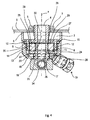
- Figure 4 is a side and sectioned view of a portion of the apparatus in Figure 1.
-
- With reference to Figures 1 to 4 there is shown an
apparatus 1 for dispensing a fluid, in particular a cleaning and/or polishing fluid for internally cleansing professional ovens and/or cookers. - The
apparatus 1 comprises ahollow collecting body 2 having a longitudinal X-axis and being provided with aninlet conduit 4 for the fluid and with acylindrical rest wall 6 connected together by aflat wall 27. Thecylindrical inlet conduit 4 comprises a threadedsurface 5 suitable for engaging with anut 7 to fix thecollecting body 2 by constraining therest wall 6 to ahorizontal wall 3 of a professional oven or kitchen, as shown more clearly in Figure 3. Near a lower portion of therest wall 6 there is provided acircumferal seat 9 that is suitable for housing aseal ring 10. Inside thecollecting body 2 there is obtained a cylindrical connectingwall 8 and which extends along the longitudinal X-axis that together with theflat wall 27 defines a containingcavity 11 and which is provided with a threadedexternal surface 12 suitable for engaging in a cylindrical threadedwall 14 obtained in ring nut means 13. Near a top portion of said threadedwall 14 there is provided a furthercircumferal seat 15 suitable for interacting with thecircumferal seat 9 and with theseal ring 10. The ring nut means 13 comprises asupport wall 16 connected to the threadedwall 14 and arranged transversely to the latter. Thesupport wall 16 is provided at its centre with a throughhousing hole 17 suitable for housing abody part 18 of arotor 36 suitable for dispensing fluid. - The
body part 18 is rotatingly connected to thecollecting body 2 in relation to the longitudinal X-axis by rotating coupling means 37 and is provided with anaxial hole 31 that faces theinlet conduit 4 and enables the fluid to flow inside therotor 36. Thebody part 18 comprises a firstcylindrical portion 20 that protrudes inside the ring nut means 13 and is suitable for engaging at the bottom with thehousing hole 17 and at the top with aseal disc 22 of the rotating coupling means 37. Theseal disc 22 is housed in acircular seat 23, internally obtained on thesupport wall 16 and interacts at the top with awasher 24. Thewasher 24 comprises alower surface 25 that is partially suitable for interacting with anupper surface 21 of theseal disc 22 and partially coming into contact with anabutment 26 provided on thebody part 18. The rotating coupling means 37 comprisesfixing means 35, arranged inside the containingcavity 11 and suitable for fixing thewasher 24 to thebody part 18 by means of a threadedcoupling 30 in such a way as to constrain theseal disc 22 axially in relation to thebody part 18. Thefixing means 35 is provided at the top with anactive surface 28 suitable for interacting with the fluid and facing theflat wall 27 in such a way as to define a disc-shapedhollow space 29. Below thebody part 18 of therotor 36 there are fixed arm means 19 extending along a transversal Y axis that is perpendicular to the longitudinal X axis. The arm means 19 is provided withpassage conduits 33 for the fluid, communicating with theaxial hole 31 nearopenings 34. The arm means 19 comprises twooutlet nozzles 32 arranged at ends of the arm means 19 that are opposite one another substantially perpendicularly both to the longitudinal X-axis and to the transverse axis Y. The twonozzles 32 are turned in directions that are opposite each other. - During operation, a cleaning and/or polishing fluid enters the
inlet conduit 4, continues inside theaxial hole 31 and flows distributing into the twopassage conduits 33 of the arm means 19. Lastly, the fluid emerges from thenozzles 32 and exerts substantially equal and opposite thrust actions in such a way as to generate a rotating torque that rotates the arm means 19 around the longitudinal X-axis. - The
seal disc 22, by interacting with thelower surface 25 of thewasher 24, counteracts the axial thrust exerted by the weight of the arm means 19 and by thebody part 18 and enables the friction to be reduced that is generated when the connection portion is rotated by the arm means 19 integral with it. The fluid that traverses theinlet conduit 4 and subsequently theaxial hole 31 may enter the inside of the disc-shapedhollow space 20; the pressure of the fluid inside the disc-shapedhollow space 29 generates on theactive surface 28 of the fixing means 35 a downward thrust along the longitudinal X axis; this thrust is directly proportionate to fluid pressure and the area of the active surface that can then be shaped according to operating needs. The thrust contributes to ensuring the contact conditions of theseal disc 22 with thewasher 24 and with thecircular seat 23, thus improving the seal of the fluid inside the ring nut means 13. - The
seal disc 22 and thewasher 24 are arranged to interact in such a way that with prolonged use thewasher 24, through the effect of sliding, progressively forms on the upper surface 21 a circular seat that increases seal conditions between theseal disc 22 and thewasher 24.
Claims (18)
- Apparatus, comprising a collecting body (2) suitable for receiving a fluid to be dispensed, a rotor (36) suitable for dispensing said fluid fitted to said collecting body (2) by rotating coupling means (37), characterised in that said collecting body (2) is shaped in such a way as to receive at the inside thereof a substantial part (18) of the body of said rotor (36).
- Apparatus according to claim 1, wherein said rotating coupling means (37) comprises fixing means (35) for fixing a seal disc (22) interposed between said rotor (36) and said collecting body (2).
- Apparatus, comprising a collecting body (2) suitable for receiving a fluid to be dispensed, a rotor (36) suitable for dispensing said fluid, said rotor being fitted to said collecting body (2) by rotating coupling means (37) characterised in that said rotating coupling means (37) comprises fixing means (35) for fixing a seal disc (22) interposed between said rotor (36) and said collecting body (2).
- Apparatus according to claim 2, or 3, wherein said rotor (36) is arranged in such a way that the weight of said rotor (36) acts on said seal disc (22) to improve the sealing against leakage of said fluid.
- Apparatus according to any preceding claim, wherein said collecting body (2) is provided with a threaded external surface (5) suitable for engaging in fixing nut means (7) for fixing said collecting body (2) to an object.
- Apparatus according to any preceding claim, wherein said collecting body (2) comprises at the inside thereof an inlet conduit (4) for a fluid arranged substantially along a longitudinal axis (X).
- Apparatus according to claim 6, wherein said substantial part (18) is provided with an axial hole (31) arranged substantially along said longitudinal axis (X) and suitable for being crossed by said fluid.
- Apparatus according to any one of claims 1, or 2, or any one of claims 4 to 7 as appended to claim 1, or 2, wherein said collecting body (2) comprises ring nut means (13) suitable for supporting said substantial part (18) rotationally in relation to said collecting body (2).
- Apparatus according to claim 8, as appended to claim 7, wherein said ring nut means (13) comprises a support wall (16) arranged transversely to said longitudinal axis (X).
- Apparatus according to claim 9, wherein said support wall (16) is provided with a housing hole (17) suitable for receiving said substantial part (18).
- Apparatus according to claim 10, wherein at the inside of said ring nut means (13) there is provided a seat (23) obtained in said support wall (16) and arranged in such a way as to surround said housing hole (17).
- Apparatus according to claim 11, as appended to claim 1, wherein in said seat (23) there is lodged a seal disc (22).
- Apparatus according to claim 11, as appended to any one of claims 2 to 10, wherein in said seat (23) there is lodged said seal disc (22).
- Apparatus according to claim 12, or 13, wherein said seal disc (22) comprises an upper surface (21) suitable for interacting in a sliding manner with a lower surface (25) of a sliding seal body (24).
- Apparatus according to claim 14, as appended to claim 4, wherein as result of the wear caused by sliding friction between said sliding seal body (24) and said seal disc (22) improvement of the sealing against leakage of said fluid can be obtained.
- Dispensing apparatus according to claim 14, or 15, wherein a portion of said lower surface (25) is fixed relative to a circular abutment (26) obtained on said substantial body part (18).
- Dispensing apparatus according to any one of claims 2 to 16, wherein said fixing means (35) comprises at the top an active surface (28) suitable for interacting with said fluid.
- Dispensing apparatus according to claim 17, wherein said active surface (28) is shaped in such a way as to define together with a flat wall (27) of said collecting body (2) a disc-shaped hollow space (29) suitable for being occupied by said fluid.
Applications Claiming Priority (2)
| Application Number | Priority Date | Filing Date | Title |
|---|---|---|---|
| ITMO20040069 ITMO20040069A1 (en) | 2004-04-01 | 2004-04-01 | DISPENSING APPARATUS |
| ITMO20040069 | 2004-04-01 |
Publications (2)
| Publication Number | Publication Date |
|---|---|
| EP1582265A2 true EP1582265A2 (en) | 2005-10-05 |
| EP1582265A3 EP1582265A3 (en) | 2008-05-14 |
Family
ID=34878857
Family Applications (1)
| Application Number | Title | Priority Date | Filing Date |
|---|---|---|---|
| EP05007134A Withdrawn EP1582265A3 (en) | 2004-04-01 | 2005-04-01 | Dispensing apparatus |
Country Status (2)
| Country | Link |
|---|---|
| EP (1) | EP1582265A3 (en) |
| IT (1) | ITMO20040069A1 (en) |
Cited By (7)
| Publication number | Priority date | Publication date | Assignee | Title |
|---|---|---|---|---|
| WO2008032138A1 (en) * | 2006-09-12 | 2008-03-20 | Calcorpress Industries S.R.L. | Washing device |
| EP1955774A2 (en) | 2007-02-10 | 2008-08-13 | Thomas Piller | Device for generating an accelerated fluid stream for treating material |
| CN101905199A (en) * | 2010-09-03 | 2010-12-08 | 任保林 | Vortex high pressure water jet water mist generating device |
| WO2015091803A1 (en) | 2013-12-20 | 2015-06-25 | i-clean Technologies GmbH | Detergent cartridge for cleaning device in ovens |
| WO2016016351A1 (en) * | 2014-08-01 | 2016-02-04 | BSH Hausgeräte GmbH | Cleaning of a household appliance |
| WO2016146564A1 (en) * | 2015-03-18 | 2016-09-22 | Gea Tuchenhagen Gmbh | Rotating cleaner |
| US20180111175A1 (en) * | 2015-03-18 | 2018-04-26 | Gea Tuchenhagen Gmbh | Rotating cleaner |
Citations (1)
| Publication number | Priority date | Publication date | Assignee | Title |
|---|---|---|---|---|
| DE19950920A1 (en) | 1999-10-21 | 2001-05-10 | Rational Ag | Rotor nozzle comprises a spring, in particular, a compression spring whose force determines the bearing force for the rotor arms |
Family Cites Families (2)
| Publication number | Priority date | Publication date | Assignee | Title |
|---|---|---|---|---|
| US3314695A (en) * | 1963-10-23 | 1967-04-18 | Fmc Corp | Fluid joint and seal assembly therefor |
| US5456412A (en) * | 1992-03-16 | 1995-10-10 | Agee; J. Christopher | High pressure surface washing device |
-
2004
- 2004-04-01 IT ITMO20040069 patent/ITMO20040069A1/en unknown
-
2005
- 2005-04-01 EP EP05007134A patent/EP1582265A3/en not_active Withdrawn
Patent Citations (1)
| Publication number | Priority date | Publication date | Assignee | Title |
|---|---|---|---|---|
| DE19950920A1 (en) | 1999-10-21 | 2001-05-10 | Rational Ag | Rotor nozzle comprises a spring, in particular, a compression spring whose force determines the bearing force for the rotor arms |
Cited By (15)
| Publication number | Priority date | Publication date | Assignee | Title |
|---|---|---|---|---|
| WO2008032138A1 (en) * | 2006-09-12 | 2008-03-20 | Calcorpress Industries S.R.L. | Washing device |
| DE102007006672B4 (en) * | 2007-02-10 | 2017-10-12 | Piller Entgrattechnik Gmbh | Apparatus for generating an accelerated fluid jet for processing material |
| EP1955774A2 (en) | 2007-02-10 | 2008-08-13 | Thomas Piller | Device for generating an accelerated fluid stream for treating material |
| DE102007006672A1 (en) * | 2007-02-10 | 2008-08-21 | Thomas Piller | Apparatus for generating an accelerated fluid jet for processing material |
| CN101905199A (en) * | 2010-09-03 | 2010-12-08 | 任保林 | Vortex high pressure water jet water mist generating device |
| CN101905199B (en) * | 2010-09-03 | 2012-07-11 | 任保林 | Vortex high pressure water jet water mist generating device |
| WO2015091803A1 (en) | 2013-12-20 | 2015-06-25 | i-clean Technologies GmbH | Detergent cartridge for cleaning device in ovens |
| DE102013021732A1 (en) * | 2013-12-20 | 2015-07-23 | i-clean Technologies GmbH | Cleaning cartridge for cleaning device in ovens |
| US9976752B2 (en) | 2013-12-20 | 2018-05-22 | i-clean Technologies GmbH | Detergent cartridge for cleaning device in ovens |
| WO2016016351A1 (en) * | 2014-08-01 | 2016-02-04 | BSH Hausgeräte GmbH | Cleaning of a household appliance |
| WO2016146564A1 (en) * | 2015-03-18 | 2016-09-22 | Gea Tuchenhagen Gmbh | Rotating cleaner |
| US20180111175A1 (en) * | 2015-03-18 | 2018-04-26 | Gea Tuchenhagen Gmbh | Rotating cleaner |
| US20180111167A1 (en) * | 2015-03-18 | 2018-04-26 | Gea Tuchenhagen Gmbh | Rotating cleaner |
| US10307801B2 (en) * | 2015-03-18 | 2019-06-04 | Gea Tuchenhagen Gmbh | Rotating cleaner |
| US10376930B2 (en) * | 2015-03-18 | 2019-08-13 | Gea Tuchenhagen Gmbh | Rotating cleaner |
Also Published As
| Publication number | Publication date |
|---|---|
| EP1582265A3 (en) | 2008-05-14 |
| ITMO20040069A1 (en) | 2004-07-01 |
Similar Documents
| Publication | Publication Date | Title |
|---|---|---|
| RU2533529C2 (en) | Assembled sprayer balance arm for dishwashing machine | |
| RU2417731C2 (en) | Domestic washing machine, in particular, dishwashing machine with improved upper hydraulic circuit | |
| EP1582265A2 (en) | Dispensing apparatus | |
| EP1264570B1 (en) | Washing machine | |
| EP2822440B1 (en) | Wash assembly applied to a washing machine and/or drying machine | |
| CN112714625B (en) | Dishwasher with Rack Mounted Duct Return Mechanism | |
| US11134825B2 (en) | Reduced sound with a rotating filter for a dishwasher | |
| WO2013122893A1 (en) | Warewash machine with removable rotating arm and related method | |
| CN108577758B (en) | Dishwasher and its filter system | |
| CN108378804B (en) | Dishwasher and its filter system | |
| CN113907681B (en) | Spray arm assembly and dish washer with same | |
| US3009470A (en) | Domestic appliance | |
| NZ569965A (en) | Appliance pump | |
| CN109798563B (en) | Range hood with self-cleaning function | |
| RU2636365C2 (en) | Dishwasher | |
| EP2483582B1 (en) | Mix-proof valve | |
| CN110859561A (en) | Spray arm and washing appliance having the same | |
| US11213184B2 (en) | Spray arm assembly and washing appliance having same | |
| CN110876597A (en) | Cover plate structure of water tank type cleaning machine | |
| CN209863733U (en) | Filtration system and household appliance having same | |
| CN222752000U (en) | Spray arm assembly and cleaning device | |
| CN209826617U (en) | Spraying system convenient to assemble and cleaning machine with spraying system | |
| CN223886744U (en) | A cleaning machine | |
| US20250369622A1 (en) | Commercial cooking appliance and method for operating such a cooking appliance | |
| CN113685860A (en) | Fume exhaust fan |
Legal Events
| Date | Code | Title | Description |
|---|---|---|---|
| PUAI | Public reference made under article 153(3) epc to a published international application that has entered the european phase |
Free format text: ORIGINAL CODE: 0009012 |
|
| AK | Designated contracting states |
Kind code of ref document: A2 Designated state(s): AT BE BG CH CY CZ DE DK EE ES FI FR GB GR HU IE IS IT LI LT LU MC NL PL PT RO SE SI SK TR |
|
| AX | Request for extension of the european patent |
Extension state: AL BA HR LV MK YU |
|
| PUAL | Search report despatched |
Free format text: ORIGINAL CODE: 0009013 |
|
| AK | Designated contracting states |
Kind code of ref document: A3 Designated state(s): AT BE BG CH CY CZ DE DK EE ES FI FR GB GR HU IE IS IT LI LT LU MC NL PL PT RO SE SI SK TR |
|
| AX | Request for extension of the european patent |
Extension state: AL BA HR LV MK YU |
|
| AKX | Designation fees paid | ||
| REG | Reference to a national code |
Ref country code: DE Ref legal event code: 8566 |
|
| STAA | Information on the status of an ep patent application or granted ep patent |
Free format text: STATUS: THE APPLICATION IS DEEMED TO BE WITHDRAWN |
|
| 18D | Application deemed to be withdrawn |
Effective date: 20081115 |