EP1582265A2 - Abgabevorrichtung für Medien - Google Patents
Abgabevorrichtung für Medien Download PDFInfo
- Publication number
- EP1582265A2 EP1582265A2 EP05007134A EP05007134A EP1582265A2 EP 1582265 A2 EP1582265 A2 EP 1582265A2 EP 05007134 A EP05007134 A EP 05007134A EP 05007134 A EP05007134 A EP 05007134A EP 1582265 A2 EP1582265 A2 EP 1582265A2
- Authority
- EP
- European Patent Office
- Prior art keywords
- fluid
- collecting body
- rotor
- seal disc
- dispensing
- Prior art date
- Legal status (The legal status is an assumption and is not a legal conclusion. Google has not performed a legal analysis and makes no representation as to the accuracy of the status listed.)
- Withdrawn
Links
Images


Classifications
-
- B—PERFORMING OPERATIONS; TRANSPORTING
- B05—SPRAYING OR ATOMISING IN GENERAL; APPLYING FLUENT MATERIALS TO SURFACES, IN GENERAL
- B05B—SPRAYING APPARATUS; ATOMISING APPARATUS; NOZZLES
- B05B3/00—Spraying or sprinkling apparatus with moving outlet elements or moving deflecting elements
- B05B3/02—Spraying or sprinkling apparatus with moving outlet elements or moving deflecting elements with rotating elements
- B05B3/025—Rotational joints
- B05B3/026—Rotational joints the fluid passing axially from one joint element to another
-
- B—PERFORMING OPERATIONS; TRANSPORTING
- B05—SPRAYING OR ATOMISING IN GENERAL; APPLYING FLUENT MATERIALS TO SURFACES, IN GENERAL
- B05B—SPRAYING APPARATUS; ATOMISING APPARATUS; NOZZLES
- B05B3/00—Spraying or sprinkling apparatus with moving outlet elements or moving deflecting elements
- B05B3/02—Spraying or sprinkling apparatus with moving outlet elements or moving deflecting elements with rotating elements
- B05B3/04—Spraying or sprinkling apparatus with moving outlet elements or moving deflecting elements with rotating elements driven by the liquid or other fluent material discharged, e.g. the liquid actuating a motor before passing to the outlet
- B05B3/06—Spraying or sprinkling apparatus with moving outlet elements or moving deflecting elements with rotating elements driven by the liquid or other fluent material discharged, e.g. the liquid actuating a motor before passing to the outlet by jet reaction
-
- B—PERFORMING OPERATIONS; TRANSPORTING
- B08—CLEANING
- B08B—CLEANING IN GENERAL; PREVENTION OF FOULING IN GENERAL
- B08B9/00—Cleaning hollow articles by methods or apparatus specially adapted thereto
- B08B9/08—Cleaning containers, e.g. tanks
- B08B9/093—Cleaning containers, e.g. tanks by the force of jets or sprays
- B08B9/0936—Cleaning containers, e.g. tanks by the force of jets or sprays using rotating jets
-
- F—MECHANICAL ENGINEERING; LIGHTING; HEATING; WEAPONS; BLASTING
- F24—HEATING; RANGES; VENTILATING
- F24C—DOMESTIC STOVES OR RANGES ; DETAILS OF DOMESTIC STOVES OR RANGES, OF GENERAL APPLICATION
- F24C14/00—Stoves or ranges having self-cleaning provisions, e.g. continuous catalytic cleaning or electrostatic cleaning
- F24C14/005—Stoves or ranges having self-cleaning provisions, e.g. continuous catalytic cleaning or electrostatic cleaning using a cleaning liquid
Definitions
- the invention relates to an apparatus for dispensing fluid, in particular an apparatus for dispensing cleaning and/or polishing fluid.
- the dispensing apparatus according to the invention is particularly suitable for internally cleansing professional ovens and/or cookers.
- DE 199 50 920 A1 discloses a dispenser that comprises an inlet conduit for the cleaning fluid inserted in a tubular element.
- the tubular element is coupled with a hollow pin by means of a threaded connection.
- a lower portion of the tubular element and a flange arranged transversely to the longitudinal axis of the hollow pin and integral with the latter are configured in such a way that the dispenser can be fixed to a top wall of an oven or cooker.
- the hollow pin is provided with radial outlet holes through which the cleaning fluid can pass.
- On a lower portion of the hollow pin a sliding bearing is mounted coaxially that is able to rotate around a longitudinal axis of the hollow pin and is provided with further radial holes arranged at radial holes of the hollow pin to enable the cleaning fluid to flow.
- Two rotating and hollow arms that extend in a transverse direction to the longitudinal axis of the hollow pin, have a respective connecting end in contact with the sliding bearing in such a way that the cleaning fluid can flow in a direction that is substantially radial to the hollow pin.
- Two nozzles are provided, each of which is arranged on each rotating arm at an end opposite the connecting end. The two nozzles are turned in opposite directions from each other.
- Two guard rings arranged coaxially to the sliding bearing and in contact with the connecting ends of the rotating arms provide to preserve the sliding bearing from powder or dirt.
- a thrust ring interacting with a preload spring supports the assembly consisting of the rotating arms, guard rings and the sliding bearing.
- a screw engaging in a lower end of the hollow pin provide to constrain the preload spring on the hollow pin and then keeps mutually the thrust ring, the sliding bearing, the guard rings and the rotating arms together.
- a cleaning fluid reaches the dispenser through the inlet conduit and flows inside the hollow pin to reach the radial holes. Subsequently, the fluid traverses the further radial holes flowing inside the rotating arms and subsequently reaches the two nozzles. Owing to the fact that the two nozzles are turned in opposite directions from each other, the emerging fluid generates in a direction that is perpendicular to the longitudinal axis components with equal and opposite force that give the rotating arms a rotating torque. In this way the rotating arms are rotated around the aforementioned longitudinal axis.
- the preload spring provides to keep the thrust ring, the sliding bearing against the flange in an axial position in such a way as to compensate volumetric variations of the sliding bearing due to thermal effects and/or wear.
- Another drawback consists of the fact that owing to the great wear due to frequent use of the dispenser the spring is no longer able to compensate for wear to the sliding bearing.
- a further drawback of the present dispenser is due to the fact that the assembly of the hollow pin of the thrust ring and of the preload spring has great overall dimensions in the direction of the longitudinal axis that reduce the volume of the treatment chamber of the oven and/or of the cooker.
- a yet further drawback of the aforementioned dispenser is due to the great weight of the thrust ring of the hollow pin and of the preload spring assembly that makes a high static torque value necessary to enable rapid operation of the rotating arms and to overcome inertia
- An object of the present invention is to improve the dispensers, in particular the dispensers of cleaning fluid suitable for cleaning professional ovens and/or cookers internally.
- Another object of the present invention is to obtain a dispenser that is structurally very simple.
- a further object of the present invention is to obtain a dispenser in which the undesired losses from leaks of cleaning fluid are minimised.
- a still further object of the present invention is to obtain a dispenser having very compact overall dimensions.
- a still further object of the present invention is to obtain a dispenser with a reduced weight that has inertia of a limited amount and that is therefore rapidly and effectively operatable by the cleaning fluid.
- an apparatus comprising a collecting body suitable for receiving a fluid to be dispensed, a rotor suitable for dispensing said fluid, said rotor being fitted to said collecting body by rotating coupling means characterised in that said collecting body is shaped in such a way as to receive at the inside thereof a substantial part of the body (18) of said rotor.
- an apparatus comprising a collecting body suitable for receiving a fluid to be dispensed, a rotor suitable for dispensing said fluid, said rotor being fitted to said collecting body by rotating coupling means characterised in that said rotating coupling means comprises fixing means for fixing a seal disc interposed between said rotor and said collecting body.
- an apparatus for dispensing a fluid that operates in a very effective manner and in which the seal conditions are improved to avoid leaks of the fluid.
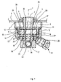
- the apparatus 1 comprises a hollow collecting body 2 having a longitudinal X-axis and being provided with an inlet conduit 4 for the fluid and with a cylindrical rest wall 6 connected together by a flat wall 27.
- the cylindrical inlet conduit 4 comprises a threaded surface 5 suitable for engaging with a nut 7 to fix the collecting body 2 by constraining the rest wall 6 to a horizontal wall 3 of a professional oven or kitchen, as shown more clearly in Figure 3.
- a circumferal seat 9 that is suitable for housing a seal ring 10.
- a cylindrical connecting wall 8 which extends along the longitudinal X-axis that together with the flat wall 27 defines a containing cavity 11 and which is provided with a threaded external surface 12 suitable for engaging in a cylindrical threaded wall 14 obtained in ring nut means 13.
- a further circumferal seat 15 suitable for interacting with the circumferal seat 9 and with the seal ring 10.
- the ring nut means 13 comprises a support wall 16 connected to the threaded wall 14 and arranged transversely to the latter.
- the support wall 16 is provided at its centre with a through housing hole 17 suitable for housing a body part 18 of a rotor 36 suitable for dispensing fluid.
- the body part 18 is rotatingly connected to the collecting body 2 in relation to the longitudinal X-axis by rotating coupling means 37 and is provided with an axial hole 31 that faces the inlet conduit 4 and enables the fluid to flow inside the rotor 36.
- the body part 18 comprises a first cylindrical portion 20 that protrudes inside the ring nut means 13 and is suitable for engaging at the bottom with the housing hole 17 and at the top with a seal disc 22 of the rotating coupling means 37.
- the seal disc 22 is housed in a circular seat 23, internally obtained on the support wall 16 and interacts at the top with a washer 24.
- the washer 24 comprises a lower surface 25 that is partially suitable for interacting with an upper surface 21 of the seal disc 22 and partially coming into contact with an abutment 26 provided on the body part 18.
- the rotating coupling means 37 comprises fixing means 35, arranged inside the containing cavity 11 and suitable for fixing the washer 24 to the body part 18 by means of a threaded coupling 30 in such a way as to constrain the seal disc 22 axially in relation to the body part 18.
- the fixing means 35 is provided at the top with an active surface 28 suitable for interacting with the fluid and facing the flat wall 27 in such a way as to define a disc-shaped hollow space 29.
- the arm means 19 is provided with passage conduits 33 for the fluid, communicating with the axial hole 31 near openings 34.
- the arm means 19 comprises two outlet nozzles 32 arranged at ends of the arm means 19 that are opposite one another substantially perpendicularly both to the longitudinal X-axis and to the transverse axis Y.
- the two nozzles 32 are turned in directions that are opposite each other.
- a cleaning and/or polishing fluid enters the inlet conduit 4, continues inside the axial hole 31 and flows distributing into the two passage conduits 33 of the arm means 19. Lastly, the fluid emerges from the nozzles 32 and exerts substantially equal and opposite thrust actions in such a way as to generate a rotating torque that rotates the arm means 19 around the longitudinal X-axis.
- the seal disc 22 by interacting with the lower surface 25 of the washer 24, counteracts the axial thrust exerted by the weight of the arm means 19 and by the body part 18 and enables the friction to be reduced that is generated when the connection portion is rotated by the arm means 19 integral with it.
- the fluid that traverses the inlet conduit 4 and subsequently the axial hole 31 may enter the inside of the disc-shaped hollow space 20; the pressure of the fluid inside the disc-shaped hollow space 29 generates on the active surface 28 of the fixing means 35 a downward thrust along the longitudinal X axis; this thrust is directly proportionate to fluid pressure and the area of the active surface that can then be shaped according to operating needs.
- the thrust contributes to ensuring the contact conditions of the seal disc 22 with the washer 24 and with the circular seat 23, thus improving the seal of the fluid inside the ring nut means 13.
- the seal disc 22 and the washer 24 are arranged to interact in such a way that with prolonged use the washer 24, through the effect of sliding, progressively forms on the upper surface 21 a circular seat that increases seal conditions between the seal disc 22 and the washer 24.
Landscapes
- Engineering & Computer Science (AREA)
- Chemical & Material Sciences (AREA)
- Mechanical Engineering (AREA)
- Chemical Kinetics & Catalysis (AREA)
- Combustion & Propulsion (AREA)
- General Engineering & Computer Science (AREA)
- Devices For Dispensing Beverages (AREA)
- Devices For Use In Laboratory Experiments (AREA)
- Sampling And Sample Adjustment (AREA)
Applications Claiming Priority (2)
| Application Number | Priority Date | Filing Date | Title |
|---|---|---|---|
| ITMO20040069 ITMO20040069A1 (it) | 2004-04-01 | 2004-04-01 | Apparato erogatore |
| ITMO20040069 | 2004-04-01 |
Publications (2)
| Publication Number | Publication Date |
|---|---|
| EP1582265A2 true EP1582265A2 (de) | 2005-10-05 |
| EP1582265A3 EP1582265A3 (de) | 2008-05-14 |
Family
ID=34878857
Family Applications (1)
| Application Number | Title | Priority Date | Filing Date |
|---|---|---|---|
| EP05007134A Withdrawn EP1582265A3 (de) | 2004-04-01 | 2005-04-01 | Abgabevorrichtung für Medien |
Country Status (2)
| Country | Link |
|---|---|
| EP (1) | EP1582265A3 (de) |
| IT (1) | ITMO20040069A1 (de) |
Cited By (7)
| Publication number | Priority date | Publication date | Assignee | Title |
|---|---|---|---|---|
| WO2008032138A1 (en) * | 2006-09-12 | 2008-03-20 | Calcorpress Industries S.R.L. | Washing device |
| EP1955774A2 (de) | 2007-02-10 | 2008-08-13 | Thomas Piller | Vorrichtung zum Erzeugen eines beschleunigten Flüssigkeitsstrahles zum Bearbeiten von Material |
| CN101905199A (zh) * | 2010-09-03 | 2010-12-08 | 任保林 | 涡流高压水射流细水雾发生装置 |
| WO2015091803A1 (de) | 2013-12-20 | 2015-06-25 | i-clean Technologies GmbH | Reinigerkartusche für reinigungsvorrichtung in öfen |
| WO2016016351A1 (de) * | 2014-08-01 | 2016-02-04 | BSH Hausgeräte GmbH | Reinigen eines haushaltsgeräts |
| WO2016146564A1 (de) * | 2015-03-18 | 2016-09-22 | Gea Tuchenhagen Gmbh | Rotierender reiniger |
| US20180111175A1 (en) * | 2015-03-18 | 2018-04-26 | Gea Tuchenhagen Gmbh | Rotating cleaner |
Citations (1)
| Publication number | Priority date | Publication date | Assignee | Title |
|---|---|---|---|---|
| DE19950920A1 (de) | 1999-10-21 | 2001-05-10 | Rational Ag | Rotordüse und Reinigungsvorrichtung mit Rotordüse |
Family Cites Families (2)
| Publication number | Priority date | Publication date | Assignee | Title |
|---|---|---|---|---|
| US3314695A (en) * | 1963-10-23 | 1967-04-18 | Fmc Corp | Fluid joint and seal assembly therefor |
| US5456412A (en) * | 1992-03-16 | 1995-10-10 | Agee; J. Christopher | High pressure surface washing device |
-
2004
- 2004-04-01 IT ITMO20040069 patent/ITMO20040069A1/it unknown
-
2005
- 2005-04-01 EP EP05007134A patent/EP1582265A3/de not_active Withdrawn
Patent Citations (1)
| Publication number | Priority date | Publication date | Assignee | Title |
|---|---|---|---|---|
| DE19950920A1 (de) | 1999-10-21 | 2001-05-10 | Rational Ag | Rotordüse und Reinigungsvorrichtung mit Rotordüse |
Cited By (15)
| Publication number | Priority date | Publication date | Assignee | Title |
|---|---|---|---|---|
| WO2008032138A1 (en) * | 2006-09-12 | 2008-03-20 | Calcorpress Industries S.R.L. | Washing device |
| DE102007006672B4 (de) * | 2007-02-10 | 2017-10-12 | Piller Entgrattechnik Gmbh | Vorrichtung zum Erzeugen eines beschleunigten Flüssigkeitsstrahles zum Bearbeiten von Material |
| EP1955774A2 (de) | 2007-02-10 | 2008-08-13 | Thomas Piller | Vorrichtung zum Erzeugen eines beschleunigten Flüssigkeitsstrahles zum Bearbeiten von Material |
| DE102007006672A1 (de) * | 2007-02-10 | 2008-08-21 | Thomas Piller | Vorrichtung zum Erzeugen eines beschleunigten Flüssigkeitsstrahles zum Bearbeiten von Material |
| CN101905199A (zh) * | 2010-09-03 | 2010-12-08 | 任保林 | 涡流高压水射流细水雾发生装置 |
| CN101905199B (zh) * | 2010-09-03 | 2012-07-11 | 任保林 | 涡流高压水射流细水雾发生装置 |
| WO2015091803A1 (de) | 2013-12-20 | 2015-06-25 | i-clean Technologies GmbH | Reinigerkartusche für reinigungsvorrichtung in öfen |
| DE102013021732A1 (de) * | 2013-12-20 | 2015-07-23 | i-clean Technologies GmbH | Reinigungskartusche für Reinigungsvorrichtung in Öfen |
| US9976752B2 (en) | 2013-12-20 | 2018-05-22 | i-clean Technologies GmbH | Detergent cartridge for cleaning device in ovens |
| WO2016016351A1 (de) * | 2014-08-01 | 2016-02-04 | BSH Hausgeräte GmbH | Reinigen eines haushaltsgeräts |
| WO2016146564A1 (de) * | 2015-03-18 | 2016-09-22 | Gea Tuchenhagen Gmbh | Rotierender reiniger |
| US20180111175A1 (en) * | 2015-03-18 | 2018-04-26 | Gea Tuchenhagen Gmbh | Rotating cleaner |
| US20180111167A1 (en) * | 2015-03-18 | 2018-04-26 | Gea Tuchenhagen Gmbh | Rotating cleaner |
| US10307801B2 (en) * | 2015-03-18 | 2019-06-04 | Gea Tuchenhagen Gmbh | Rotating cleaner |
| US10376930B2 (en) * | 2015-03-18 | 2019-08-13 | Gea Tuchenhagen Gmbh | Rotating cleaner |
Also Published As
| Publication number | Publication date |
|---|---|
| EP1582265A3 (de) | 2008-05-14 |
| ITMO20040069A1 (it) | 2004-07-01 |
Similar Documents
| Publication | Publication Date | Title |
|---|---|---|
| RU2533529C2 (ru) | Распылительное коромысло в сборе для посудомоечной машины | |
| RU2417731C2 (ru) | Бытовая моечная машина, в частности посудомоечная машина с усовершенствованным верхним гидравлическим контуром | |
| EP1582265A2 (de) | Abgabevorrichtung für Medien | |
| EP1264570B1 (de) | Geschirrspülmaschine | |
| EP2822440B1 (de) | Waschanordnung für eine waschmaschine und/oder trockenmaschine | |
| CN112714625B (zh) | 具有架装式导管返回机构的洗碗机 | |
| US11134825B2 (en) | Reduced sound with a rotating filter for a dishwasher | |
| WO2013122893A1 (en) | Warewash machine with removable rotating arm and related method | |
| CN108577758B (zh) | 洗碗机及其过滤系统 | |
| CN108378804B (zh) | 洗碗机及其过滤系统 | |
| CN113907681B (zh) | 喷臂组件及具有其的洗碗机 | |
| US3009470A (en) | Domestic appliance | |
| NZ569965A (en) | Appliance pump | |
| CN109798563B (zh) | 一种具有自清洁功能的吸油烟机 | |
| RU2636365C2 (ru) | Посудомоечная машина | |
| EP2483582B1 (de) | Mischsicheres ventil | |
| CN110859561A (zh) | 喷臂及具有其的洗涤电器 | |
| US11213184B2 (en) | Spray arm assembly and washing appliance having same | |
| CN110876597A (zh) | 一种水槽式清洗机的盖板结构 | |
| CN209863733U (zh) | 过滤系统及具有其的家用电器 | |
| CN222752000U (zh) | 喷淋臂组件及清洗装置 | |
| CN209826617U (zh) | 一种方便组装的喷淋系统及具有其的清洗机 | |
| CN223886744U (zh) | 一种清洗机 | |
| US20250369622A1 (en) | Commercial cooking appliance and method for operating such a cooking appliance | |
| CN113685860A (zh) | 油烟机 |
Legal Events
| Date | Code | Title | Description |
|---|---|---|---|
| PUAI | Public reference made under article 153(3) epc to a published international application that has entered the european phase |
Free format text: ORIGINAL CODE: 0009012 |
|
| AK | Designated contracting states |
Kind code of ref document: A2 Designated state(s): AT BE BG CH CY CZ DE DK EE ES FI FR GB GR HU IE IS IT LI LT LU MC NL PL PT RO SE SI SK TR |
|
| AX | Request for extension of the european patent |
Extension state: AL BA HR LV MK YU |
|
| PUAL | Search report despatched |
Free format text: ORIGINAL CODE: 0009013 |
|
| AK | Designated contracting states |
Kind code of ref document: A3 Designated state(s): AT BE BG CH CY CZ DE DK EE ES FI FR GB GR HU IE IS IT LI LT LU MC NL PL PT RO SE SI SK TR |
|
| AX | Request for extension of the european patent |
Extension state: AL BA HR LV MK YU |
|
| AKX | Designation fees paid | ||
| REG | Reference to a national code |
Ref country code: DE Ref legal event code: 8566 |
|
| STAA | Information on the status of an ep patent application or granted ep patent |
Free format text: STATUS: THE APPLICATION IS DEEMED TO BE WITHDRAWN |
|
| 18D | Application deemed to be withdrawn |
Effective date: 20081115 |