EP1582267A1 - Appareil et procédé pour nettoyer une cabine de pulvérisation de poudre - Google Patents
Appareil et procédé pour nettoyer une cabine de pulvérisation de poudre Download PDFInfo
- Publication number
- EP1582267A1 EP1582267A1 EP05405235A EP05405235A EP1582267A1 EP 1582267 A1 EP1582267 A1 EP 1582267A1 EP 05405235 A EP05405235 A EP 05405235A EP 05405235 A EP05405235 A EP 05405235A EP 1582267 A1 EP1582267 A1 EP 1582267A1
- Authority
- EP
- European Patent Office
- Prior art keywords
- frame
- cabin
- suction
- cleaning
- booth
- Prior art date
- Legal status (The legal status is an assumption and is not a legal conclusion. Google has not performed a legal analysis and makes no representation as to the accuracy of the status listed.)
- Granted
Links
- 238000004140 cleaning Methods 0.000 title claims abstract description 34
- 238000000034 method Methods 0.000 title claims abstract description 18
- 229940098458 powder spray Drugs 0.000 title description 2
- 239000000843 powder Substances 0.000 claims abstract description 40
- 239000011248 coating agent Substances 0.000 claims abstract description 18
- 238000000576 coating method Methods 0.000 claims abstract description 18
- 239000000725 suspension Substances 0.000 claims description 2
- 108010066057 cabin-1 Proteins 0.000 description 7
- 238000011161 development Methods 0.000 description 4
- 230000018109 developmental process Effects 0.000 description 4
- 238000007664 blowing Methods 0.000 description 3
- 238000007796 conventional method Methods 0.000 description 2
- 239000002184 metal Substances 0.000 description 2
- 230000001464 adherent effect Effects 0.000 description 1
- 108010066114 cabin-2 Proteins 0.000 description 1
- 230000001419 dependent effect Effects 0.000 description 1
- 230000005686 electrostatic field Effects 0.000 description 1
- 239000003344 environmental pollutant Substances 0.000 description 1
- 238000012423 maintenance Methods 0.000 description 1
- 238000004519 manufacturing process Methods 0.000 description 1
- 239000000463 material Substances 0.000 description 1
- 238000012986 modification Methods 0.000 description 1
- 230000004048 modification Effects 0.000 description 1
- 239000003973 paint Substances 0.000 description 1
- 238000010422 painting Methods 0.000 description 1
- 239000002245 particle Substances 0.000 description 1
- 231100000719 pollutant Toxicity 0.000 description 1
- 238000011084 recovery Methods 0.000 description 1
- 238000007789 sealing Methods 0.000 description 1
Images


Classifications
-
- B—PERFORMING OPERATIONS; TRANSPORTING
- B08—CLEANING
- B08B—CLEANING IN GENERAL; PREVENTION OF FOULING IN GENERAL
- B08B5/00—Cleaning by methods involving the use of air flow or gas flow
- B08B5/04—Cleaning by suction, with or without auxiliary action
-
- B—PERFORMING OPERATIONS; TRANSPORTING
- B05—SPRAYING OR ATOMISING IN GENERAL; APPLYING FLUENT MATERIALS TO SURFACES, IN GENERAL
- B05B—SPRAYING APPARATUS; ATOMISING APPARATUS; NOZZLES
- B05B14/00—Arrangements for collecting, re-using or eliminating excess spraying material
- B05B14/40—Arrangements for collecting, re-using or eliminating excess spraying material for use in spray booths
- B05B14/41—Arrangements for collecting, re-using or eliminating excess spraying material for use in spray booths by cleaning the walls of the booth
-
- B—PERFORMING OPERATIONS; TRANSPORTING
- B08—CLEANING
- B08B—CLEANING IN GENERAL; PREVENTION OF FOULING IN GENERAL
- B08B9/00—Cleaning hollow articles by methods or apparatus specially adapted thereto
-
- B—PERFORMING OPERATIONS; TRANSPORTING
- B08—CLEANING
- B08B—CLEANING IN GENERAL; PREVENTION OF FOULING IN GENERAL
- B08B9/00—Cleaning hollow articles by methods or apparatus specially adapted thereto
- B08B9/08—Cleaning containers, e.g. tanks
Definitions
- the present invention relates to a device and a method for cleaning a powder coating booth and a powder coating booth equipped with suction devices for suction or cleaning of Powder residue is equipped.
- the suction devices drive to along the cabin walls.
- the present invention is therefore the task underlying, an apparatus and method for cleaning to create a booth for powder coating, which eliminated these and other disadvantages.
- the object is achieved by a device for cleaning a Cabin for powder coating with the characteristics of Patent claim 1 solved.
- the inventive device for cleaning a cabin for powder coating has a mobile frame on, which is movable along the insides of the cabin.
- the frame includes suction nozzles to remove residual powder from the insides to extract the cabin.
- the task is also performed by a method for cleaning a booth for powder coating with the characteristics of Patent claim 13 solved.
- the suction nozzles are arranged and the frame is formed such that the air directly at the Surface of the inside of the cabin is accelerated. This makes the insides of the cabin even better free from powder residues.
- the frame has a wiper strip. Also this makes the insides of the cabin even better free from powder residues.
- the suction nozzles on those sides of the frame are arranged, the ceiling, the side walls and associated with the floor of the cabin. This can be done in one operation the ceiling, the side walls and the floor the cab be cleaned at the same time.
- a stationary suction chamber which has a Suction duct is connected to the frame.
- the suction chamber comprises a movable belt with an opening into which the suction channel opens.
- the frame inside a cavity, which with the Suction channel is connected.
- the frame to be provided with a slot at the top. This has the advantage that the transport of the workpieces through the frame not hindered. If the system is in coating operation, the workpieces are going through the frame transported through.
- the frame has the shape of the cabin.
- the frame points on both sides of the suction nozzles respectively a groove into which the wiper strip can be inserted.
- the frame have a transport suspension, by means of which of the frames is movable through the cabin.
- the wiper strip have a sponge.
- the suction devices to a Sliding frame attached, the side slits and inside a cavity for removing the sucked air having.
- the frame is included in the invention Sponges equipped to complete the powder removal. These sponges are removable and can be attached the frame can be grown in two different places. You are in the frame feed direction advantageously behind the suction devices.
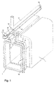
- the powder coating equipment includes a cabin or a tunnel 1 with open ends.
- the powder coating plant comprises also one or more conventional powder spray guns, which are not shown in Fig. 1, however.
- the upper Side of the cabin is in its entire length by one Split 2 slot. Both drive through this slot 2 the funding for the parts to be coated as well the mobile cleaning device, which as a whole with designated by the reference numeral 3.
- This mobile cleaning device 3 has a frame 4 with a cavity inside to the flow of the extracted Air on.
- the frame 4 is like the inner profile shaped the car 1 and also has an upper opening 5 on to the above, not shown funding to let pass unhindered.
- the suction chamber 13 is box-shaped and narrow and has two long and two short walls 18 with a slot 17 in between.
- the slot 17 is as long as the cabin.
- One annular metal band 14 is about pulleys or Deflection rollers 15 deflected and abuts against the walls 18.
- the suction 12th is attached to the belt 14 in the region of the hole 16 and opens into the hole 16. Due to the negative pressure, which in the Suction chamber 13 prevails, the tape 14 remains against the the suction chamber 13 provided sealing edges of the walls 18th pressed.
- the band 14 running on the pulleys 15, follows the movements of the mobile cleaning device 3.
- the band 14 is, as mentioned, in the region of the hole 16th connected via the suction channel 12 with the frame 4 and thus creates a connection between the mobile suction means, which in the present embodiment by the frame 4 and the suction channel 12 are formed, and the fixed suction means, which in the present Embodiment formed by the suction chamber 13 become. This allows the air from the mobile suction flow to the fixed suction means.
- the seal between the band 14 and the walls 18 takes place by the negative pressure that the suction in the suction chamber 13 generated.
- the band 14 is due to the negative pressure constantly close to the edge of the opening 17.
- the cleaning is done the powder coating booth fast and effective.
- the cleaning takes place due to the extracted air, the sucked through the slot 7 on the mobile frame 4 Powder carries with it.
- the frame 4 drives through the whole Cabin 1 through and sucks the entire on the cabin walls adherent residual powder in a single pass from. After the frame 4 has passed through the car 1, the cleaning process is completed until further notice.
- the frame 4 remains, as shown in Figure 2, as long as outside the cabin 1 stand until another cleaning process is required.
- a renewed cleaning of the car 1 by the frame 4 driven back through the cabin 1 through is then again to the original shown in Figure 1 Take position.
- the extracted from the cabin walls powder is on the Slot 7, the existing inside the frame 4 cavity and the suction channel 12 is transported into the suction chamber 13. From there, the powder becomes a conventional one Powder recovery plant continued where it filtered and is cleaned.
- the cleaning is done by the damp Sponge on the mobile frame 4 more effective. Also possible electrostatic fields caused by friction of powder particles be created on each other and on the cabin walls thereby degraded.
- the invention is not limited to the use of sponges 10, which are attached to the frame 4, limited. in principle Any type of wiper strip can be used, which is suitable for the residual powder from the insides of the To wipe off cubicle 1.
- the wet sponge 10 is in the first groove 8 (Fig. 4) or behind the suction.
- the sponge 10 Before rewinding in the opposite direction will the sponge 10 is taken out of the groove 8 and into the Groove 9 on the opposite side of the slot. 7 put into it. As a result, the sponge 10 works alternately on the two sides, wear more evenly and thus has a longer life.
- the sponge 10 can be in the groove 8 or 9 quickly and just insert it, because he is on a support strip 11 made of a flexible material, such as plastic or the like, is attached.
- This carrier strip 11 is inserted into one of the grooves 8 or 9 and stops the sponge 10 firmly in position. Because the sponge 10 thicker than the space between the mobile Frame 4 and the cabin wall, it is flattened and bends when the frame 4 into the cabin 1 inside moves. This is the contact between sponge 10 and the walls guaranteed at all times.
- the in the conventional Method piston used are no longer required what among other things to a space savings leads. Because the sponge 10 at the frame corners no piston stroke exposed, he can without a risk of tearing one consist of single strips.
Landscapes
- Engineering & Computer Science (AREA)
- Mechanical Engineering (AREA)
- Details Or Accessories Of Spraying Plant Or Apparatus (AREA)
- Cleaning In General (AREA)
- Coating Apparatus (AREA)
Applications Claiming Priority (4)
| Application Number | Priority Date | Filing Date | Title |
|---|---|---|---|
| ITMI20040633 ITMI20040633A1 (it) | 2004-03-30 | 2004-03-30 | Cabine di verniciatura a polveri con dispositivo di aspirazione delle polveri residue |
| ITMI20040632 | 2004-03-30 | ||
| ITMI20040633 | 2004-03-30 | ||
| ITMI20040632 ITMI20040632A1 (it) | 2004-03-30 | 2004-03-30 | Cabine di verniciatura a polveri con dispositivo di aspirazione delle polveri residue e relativo netodo |
Publications (2)
| Publication Number | Publication Date |
|---|---|
| EP1582267A1 true EP1582267A1 (fr) | 2005-10-05 |
| EP1582267B1 EP1582267B1 (fr) | 2007-09-19 |
Family
ID=34889168
Family Applications (1)
| Application Number | Title | Priority Date | Filing Date |
|---|---|---|---|
| EP05405235A Expired - Lifetime EP1582267B1 (fr) | 2004-03-30 | 2005-03-10 | Appareil et procédé pour nettoyer une cabine de pulvérisation de poudre |
Country Status (4)
| Country | Link |
|---|---|
| US (1) | US7582169B2 (fr) |
| EP (1) | EP1582267B1 (fr) |
| DE (1) | DE502005001505D1 (fr) |
| ES (1) | ES2294668T3 (fr) |
Cited By (2)
| Publication number | Priority date | Publication date | Assignee | Title |
|---|---|---|---|---|
| US7582169B2 (en) | 2004-03-30 | 2009-09-01 | J. Wagner Ag | Device and method for cleaning a powder coating booth |
| ITUB20153210A1 (it) * | 2015-08-24 | 2017-02-24 | Siver S R L | Cabina di verniciatura |
Families Citing this family (1)
| Publication number | Priority date | Publication date | Assignee | Title |
|---|---|---|---|---|
| PL228836B1 (pl) * | 2016-01-26 | 2018-05-30 | Potocki Piotr Eco Line | Kabina lakiernicza |
Citations (4)
| Publication number | Priority date | Publication date | Assignee | Title |
|---|---|---|---|---|
| US3800358A (en) * | 1972-05-08 | 1974-04-02 | J Ryan | Duct cleaning apparatus |
| DE4019556A1 (de) * | 1989-06-16 | 1990-12-20 | Farb Tec Beschichtung | Kabine zum spruehbeschichten von gegenstaenden mit pulverfoermigem beschichtungsmaterial ("c") |
| EP0433589A2 (fr) * | 1989-12-19 | 1991-06-26 | Wagner International Ag | Installation de poudrage électrostatique |
| US5346553A (en) * | 1989-06-16 | 1994-09-13 | Farb-Tec Gesellschaft Fur Beschichtungskabinen | Cabin for spray-coating workpieces with material in powder form |
Family Cites Families (6)
| Publication number | Priority date | Publication date | Assignee | Title |
|---|---|---|---|---|
| CH668008A5 (de) * | 1985-04-30 | 1988-11-30 | H U Ramseier Fa | Elektrostatische pulverbeschichtungsanlage. |
| DE3712437A1 (de) * | 1987-04-11 | 1988-10-20 | Gema Ransburg Ag | Pulverbeschichtungskabine |
| DE19500873A1 (de) * | 1995-01-13 | 1996-07-18 | Gema Volstatic Ag | Sprühbeschichtungsvorrichtung |
| DE19522186A1 (de) | 1995-06-19 | 1997-03-20 | Wagner Int | Reinigungseinrichtung für eine Pulverbeschichtungskabine |
| DE10249999B3 (de) * | 2002-10-26 | 2004-04-15 | EISENMANN Maschinenbau KG (Komplementär: Eisenmann-Stiftung) | Vorrichtung zur Absaugung bestimmter Flächenbereiche an bepulverten Fahrzeugrädern |
| EP1582267B1 (fr) | 2004-03-30 | 2007-09-19 | J. Wagner AG | Appareil et procédé pour nettoyer une cabine de pulvérisation de poudre |
-
2005
- 2005-03-10 EP EP05405235A patent/EP1582267B1/fr not_active Expired - Lifetime
- 2005-03-10 DE DE502005001505T patent/DE502005001505D1/de not_active Expired - Lifetime
- 2005-03-10 ES ES05405235T patent/ES2294668T3/es not_active Expired - Lifetime
- 2005-03-28 US US11/091,863 patent/US7582169B2/en not_active Expired - Fee Related
Patent Citations (4)
| Publication number | Priority date | Publication date | Assignee | Title |
|---|---|---|---|---|
| US3800358A (en) * | 1972-05-08 | 1974-04-02 | J Ryan | Duct cleaning apparatus |
| DE4019556A1 (de) * | 1989-06-16 | 1990-12-20 | Farb Tec Beschichtung | Kabine zum spruehbeschichten von gegenstaenden mit pulverfoermigem beschichtungsmaterial ("c") |
| US5346553A (en) * | 1989-06-16 | 1994-09-13 | Farb-Tec Gesellschaft Fur Beschichtungskabinen | Cabin for spray-coating workpieces with material in powder form |
| EP0433589A2 (fr) * | 1989-12-19 | 1991-06-26 | Wagner International Ag | Installation de poudrage électrostatique |
Non-Patent Citations (1)
| Title |
|---|
| "AUTOMATISIERUNGSKONZEPT BEI DER PULVERLACKIERUNG", BETRIEBSTECHNIK, TECHNISCHER VERLAG RESCH KG. GRAEFELFING, DE, vol. 37, no. 4, 26 June 1996 (1996-06-26), pages 20, XP000599395, ISSN: 0409-2791 * |
Cited By (3)
| Publication number | Priority date | Publication date | Assignee | Title |
|---|---|---|---|---|
| US7582169B2 (en) | 2004-03-30 | 2009-09-01 | J. Wagner Ag | Device and method for cleaning a powder coating booth |
| ITUB20153210A1 (it) * | 2015-08-24 | 2017-02-24 | Siver S R L | Cabina di verniciatura |
| WO2017033074A1 (fr) * | 2015-08-24 | 2017-03-02 | Siver S.R.L. | Cabine d'application de revêtement |
Also Published As
| Publication number | Publication date |
|---|---|
| EP1582267B1 (fr) | 2007-09-19 |
| ES2294668T3 (es) | 2008-04-01 |
| US20050217704A1 (en) | 2005-10-06 |
| DE502005001505D1 (de) | 2007-10-31 |
| US7582169B2 (en) | 2009-09-01 |
Similar Documents
| Publication | Publication Date | Title |
|---|---|---|
| DE4215602C2 (de) | Vorrichtung zum Entfernen von Flüssigkeit von der Oberfläche eines bewegten Bandes | |
| DE3500005A1 (de) | Beschichtungskabine zum ueberziehen der oberflaeche von werkstuecken mit beschichtungspulver | |
| EP0478649B1 (fr) | Cabine pour l'enduction d'objets avec un materiau pulverulent | |
| EP0727258A1 (fr) | Dispositif de nettoyage d'un cabine de poudrage | |
| DE4012676A1 (de) | Kabine fuer elektrostatische lackierung | |
| DE2947755C2 (fr) | ||
| DE1617959A1 (de) | Verfahren und Vorrichtung zur aseptischen Entfernung von Fluessigkeit von einem bahnfoermigen Verpackungsmaterial | |
| DE2823958C2 (de) | Verfahren und Vorrichtung zur Spritzbehandlung, insbesondere zum Spritzlackieren von Gegenständen | |
| DE1786108C3 (de) | Vorrichtung zum kontinuierlichen Entstauben von Materialbahnen | |
| EP1582267B1 (fr) | Appareil et procédé pour nettoyer une cabine de pulvérisation de poudre | |
| DE102007002935A1 (de) | Reinigungsvorrichtung für eine vorzugsweise ebene Fläche, insbesondere ein Fenster | |
| DE9310642U1 (de) | Flächenstrahlvorrichtung | |
| EP0391441A2 (fr) | Outil de sablage portatif pour le sablage des surfaces | |
| DE3927980C1 (en) | Appts. to remove lint from cleaning installation - has cleaning belt associated with suction nozzle with overflow shuttles | |
| DE3023044A1 (de) | Kabine zur oberflaechenbeschichtung von gegenstaenden | |
| EP0393008A2 (fr) | Appareil pour le nettoyage et séchage des plaques de verre | |
| CH665966A5 (de) | Pulverbeschichtungskabine mit bodenfilter und absauganlage. | |
| DE102009032907B3 (de) | Vorrichtung zum Entfernen von Rückständen von der Oberfläche eines bewegten Bandes sowie Bandbearbeitungsanlage | |
| DE102010060421A1 (de) | Vorrichtung zum Abscheiden von Feststoffaerosolen aus der Luft | |
| DE3730273A1 (de) | Vorrichtung zum absaugen von rauch und schadstoffen | |
| AT402477B (de) | Verfahren zum reinigen einer vliesartigen filtermatte | |
| DE9205280U1 (de) | Reinigungsanlage für Textilmaschinen | |
| WO1998024353A1 (fr) | Chenilles de maintien pour nettoyeuse automatique | |
| CH581503A5 (en) | Electrostatic powder coating tunnel with cleaning system - has tunnel made of wire screens, cleaned from outside by travelling air blast | |
| DE2436931C3 (de) | Gerät zum Reinigen von Gebäudeaußenwänden |
Legal Events
| Date | Code | Title | Description |
|---|---|---|---|
| PUAI | Public reference made under article 153(3) epc to a published international application that has entered the european phase |
Free format text: ORIGINAL CODE: 0009012 |
|
| AK | Designated contracting states |
Kind code of ref document: A1 Designated state(s): AT BE BG CH CY CZ DE DK EE ES FI FR GB GR HU IE IS IT LI LT LU MC NL PL PT RO SE SI SK TR |
|
| AX | Request for extension of the european patent |
Extension state: AL BA HR LV MK YU |
|
| 17P | Request for examination filed |
Effective date: 20060405 |
|
| AKX | Designation fees paid |
Designated state(s): AT BE BG CH CY CZ DE DK EE ES FI FR GB GR HU IE IS IT LI LT LU MC NL PL PT RO SE SI SK TR |
|
| GRAP | Despatch of communication of intention to grant a patent |
Free format text: ORIGINAL CODE: EPIDOSNIGR1 |
|
| RBV | Designated contracting states (corrected) |
Designated state(s): DE ES FR GB IT |
|
| GRAS | Grant fee paid |
Free format text: ORIGINAL CODE: EPIDOSNIGR3 |
|
| RBV | Designated contracting states (corrected) |
Designated state(s): DE ES FR IT SE |
|
| GRAA | (expected) grant |
Free format text: ORIGINAL CODE: 0009210 |
|
| AK | Designated contracting states |
Kind code of ref document: B1 Designated state(s): DE ES FR IT SE |
|
| REF | Corresponds to: |
Ref document number: 502005001505 Country of ref document: DE Date of ref document: 20071031 Kind code of ref document: P |
|
| REG | Reference to a national code |
Ref country code: SE Ref legal event code: TRGR |
|
| REG | Reference to a national code |
Ref country code: ES Ref legal event code: FG2A Ref document number: 2294668 Country of ref document: ES Kind code of ref document: T3 |
|
| ET | Fr: translation filed | ||
| PLBE | No opposition filed within time limit |
Free format text: ORIGINAL CODE: 0009261 |
|
| STAA | Information on the status of an ep patent application or granted ep patent |
Free format text: STATUS: NO OPPOSITION FILED WITHIN TIME LIMIT |
|
| 26N | No opposition filed |
Effective date: 20080620 |
|
| PGFP | Annual fee paid to national office [announced via postgrant information from national office to epo] |
Ref country code: IT Payment date: 20120329 Year of fee payment: 8 |
|
| PGFP | Annual fee paid to national office [announced via postgrant information from national office to epo] |
Ref country code: ES Payment date: 20120426 Year of fee payment: 8 |
|
| PGFP | Annual fee paid to national office [announced via postgrant information from national office to epo] |
Ref country code: DE Payment date: 20130331 Year of fee payment: 9 Ref country code: FR Payment date: 20130329 Year of fee payment: 9 Ref country code: SE Payment date: 20130312 Year of fee payment: 9 |
|
| REG | Reference to a national code |
Ref country code: DE Ref legal event code: R119 Ref document number: 502005001505 Country of ref document: DE |
|
| REG | Reference to a national code |
Ref country code: SE Ref legal event code: EUG |
|
| PG25 | Lapsed in a contracting state [announced via postgrant information from national office to epo] |
Ref country code: SE Free format text: LAPSE BECAUSE OF NON-PAYMENT OF DUE FEES Effective date: 20140311 |
|
| REG | Reference to a national code |
Ref country code: FR Ref legal event code: ST Effective date: 20141128 |
|
| REG | Reference to a national code |
Ref country code: DE Ref legal event code: R119 Ref document number: 502005001505 Country of ref document: DE Effective date: 20141001 |
|
| PG25 | Lapsed in a contracting state [announced via postgrant information from national office to epo] |
Ref country code: DE Free format text: LAPSE BECAUSE OF NON-PAYMENT OF DUE FEES Effective date: 20141001 Ref country code: FR Free format text: LAPSE BECAUSE OF NON-PAYMENT OF DUE FEES Effective date: 20140331 |
|
| PG25 | Lapsed in a contracting state [announced via postgrant information from national office to epo] |
Ref country code: IT Free format text: LAPSE BECAUSE OF NON-PAYMENT OF DUE FEES Effective date: 20140310 |
|
| REG | Reference to a national code |
Ref country code: ES Ref legal event code: FD2A Effective date: 20150507 |
|
| PG25 | Lapsed in a contracting state [announced via postgrant information from national office to epo] |
Ref country code: ES Free format text: LAPSE BECAUSE OF NON-PAYMENT OF DUE FEES Effective date: 20140311 |