EP1582276A2 - Matrice de laminage - Google Patents
Matrice de laminage Download PDFInfo
- Publication number
- EP1582276A2 EP1582276A2 EP05006968A EP05006968A EP1582276A2 EP 1582276 A2 EP1582276 A2 EP 1582276A2 EP 05006968 A EP05006968 A EP 05006968A EP 05006968 A EP05006968 A EP 05006968A EP 1582276 A2 EP1582276 A2 EP 1582276A2
- Authority
- EP
- European Patent Office
- Prior art keywords
- bite
- processing teeth
- finishing
- trough
- die
- Prior art date
- Legal status (The legal status is an assumption and is not a legal conclusion. Google has not performed a legal analysis and makes no representation as to the accuracy of the status listed.)
- Withdrawn
Links
Images



Classifications
-
- B—PERFORMING OPERATIONS; TRANSPORTING
- B21—MECHANICAL METAL-WORKING WITHOUT ESSENTIALLY REMOVING MATERIAL; PUNCHING METAL
- B21H—MAKING PARTICULAR METAL OBJECTS BY ROLLING, e.g. SCREWS, WHEELS, RINGS, BARRELS, BALLS
- B21H3/00—Making helical bodies or bodies having parts of helical shape
- B21H3/02—Making helical bodies or bodies having parts of helical shape external screw-threads ; Making dies for thread rolling
-
- B—PERFORMING OPERATIONS; TRANSPORTING
- B21—MECHANICAL METAL-WORKING WITHOUT ESSENTIALLY REMOVING MATERIAL; PUNCHING METAL
- B21H—MAKING PARTICULAR METAL OBJECTS BY ROLLING, e.g. SCREWS, WHEELS, RINGS, BARRELS, BALLS
- B21H3/00—Making helical bodies or bodies having parts of helical shape
- B21H3/02—Making helical bodies or bodies having parts of helical shape external screw-threads ; Making dies for thread rolling
- B21H3/06—Making by means of profiled members other than rolls, e.g. reciprocating flat dies or jaws, moved longitudinally or curvilinearly with respect to each other
Definitions
- the present invention relates to a rolling die for rolling bolts or screws. More particularly, the invention relates to a rolling die having stabilized formation precision and high durability.
- Fasteners such as bolts or screws, continuously form screw crests and troughs on the peripheral surface with each single rotation by holding a rod-like workpiece between a pair of flat die pieces provided with moderately inclined processing teeth on one side surface, and relatively moving one flat die with respect to the other side surface.
- the processing teeth have the same cross-sectional shape, extending from a bite portion that includes a starting point on one surface side to a roll-off portion that includes an end point.
- the raw material of bolts or screws has evolved from carbon steel or processed steel to relatively hard chrome molybdenum steel (SCM type steel).
- SCM type steel chrome molybdenum steel
- cold die steel is an example of raw materials used for rolling dies.
- the present invention is directed to solve one or more of these problems and to provide a rolling die with processing teeth at a bite portion that include an initial bite starting point in the workpiece having a cross-sectional shape with an obtuse angle greater than that of finish processing teeth, the obtuse angle becoming successively greater from the bite portion to the finishing portion.
- a rolling die includes a bite portion having bite processing teeth at a bite starting point for a workpiece, and a finishing portion having finishing processing teeth.
- the bite processing teeth at the starting point in the bite portion have lower tooth height than the finishing processing teeth in the finishing portion.
- the bite processing teeth have a larger tooth tip angle and a larger trough angle than the finishing processing teeth.
- Fig. 1 illustrates a rolling die according to one exemplary embodiment of the present invention
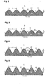
- Fig. 2 is a cross-sectional view of a bite starting point of a bite portion of the rolling die of Fig. 1;
- Fig. 3 is a cross-sectional view of an interim point of the bite portion of the rolling die of Fig. 1;
- Fig. 4 is a cross-sectional view of an different interim point of the bite portion of the rolling die of Fig. 1;
- Fig. 5 is a cross-sectional view of a finishing portion of the rolling die of Fig. 1;
- Fig. 6 illustrates the bite portion and the finishing portion of the rolling die of Fig. 1;
- Fig. 7 illustrates a workpiece being processed at the starting point of the rolling die of Fig. 1;
- Fig. 8 is a cross-sectional view of the work piece and the rolling die of Fig. 7;
- Fig. 9 illustrates a workpiece being processed at the interim point of the bite portion of the rolling die of Fig. 1;
- Fig. 10 is a cross-sectional view of the workpiece and the rolling die of Fig. 9;
- Fig. 11 illustrates a working piece at a different interim point of the bite portion of the rolling die of Fig. 1;
- Fig. 12 is a cross-sectional view of the work piece and the rolling die of Fig. 11;
- Fig. 13 illustrates a working piece at the finishing portion of the rolling die of Fig. 1;
- Fig. 14 is a cross-sectional view of the workpiece and the rolling die of Fig. 13;
- Fig. 15 illustrates a rolling die according to another exemplary embodiment of the present invention.
- Fig. 16 illustrates a workpiece being processed by the rolling die of Fig. 15.
- a rolling die includes a bite portion having bite processing teeth and a finishing portion having finishing processing teeth.
- the bite portion includes bite processing teeth at a bite starting point for a workpiece.
- the processing teeth at the starting point in the bite portion have a lower tooth height than the processing teeth in the finishing portion, and the bite processing teeth at the starting point in the bite portion have a larger tooth tip angle and a larger trough angle than the finishing processing teeth in the finishing portion.
- the processing teeth of the bite starting point are shallow and have an obtuse angle for the initial bite at a workpiece processed for bolts and the like, cracking or localized breakage becomes less likely to occur at the tooth tip at the bite portion that includes the bite starting point. Furthermore, since the cross-sectional shape of the bite processing teeth gradually changes from the bite starting point to the finishing portion, successively deeper and shaper bites are formed in the workpiece. Consequently, a desired shape of screw crest and trough can be precisely formed even in a workpiece made of a hard material. This can provide more precise processing of a workpiece with a hard material and allows a longer product life for the rolling die.
- Tooth height refers to the distance between the tooth tip and the tooth bottom of the processing teeth
- the tooth tip angle refers to the angle (so-called crest angle) having its center at the tooth tip
- the trough angle refers to the angle between two processing teeth located next to each other.
- the tooth height of the bite processing teeth becomes continuously higher toward the finishing portion, and a trough becomes deeper and wider from the bite portion to the finishing portion.
- the processing teeth at the bite starting point provide bites that are shallow and obtuse.
- the processing teeth next to the processing teeth at the bite starting point provide shallow obtuse bites.
- Another set of processing teeth at the bite portion provide deeper and sharper bites to the workpiece.
- a desired shape of screw crests and troughs is precisely formed.
- the "trough bottom” as used here refers to a portion at a trough between the processing teeth, in which its trough angle is smaller than the trough angle at the tooth tip.
- the tooth tip angle and the trough bottom angle in the bite portion may be 60 degrees or greater, and the trough angle between the processing teeth of the finishing portion may correspond to a standard valued set for a screw.
- the rolling die may process the workpiece more accurately with gradually deeper and sharper processing teeth angles and provides a longer product life.
- the tooth tip and trough angle of the processing teeth at the bite starting point may be 90 degrees or greater, and the tooth tip and trough angle of the processing teeth at the finishing portion may be, for example, 60 degrees or greater.
- the rolling die may be provided with a roll-off portion with a roll-off angle in the finishing portion at the opposite side from the bite portion.
- the roll-off portion may include processing teeth having the same tooth height and tooth tip angle as the processing teeth at the finishing portion. With such a roll-off portion, it is possible to process a workpiece with desired screw crests and troughs and release the workpiece from the rolling die smoothly.
- a rolling die may include a pair of die members of a solid-rectangular shape that has the bite portion and the finishing portion on its side.
- the rolling die may provide rolling by means of a set of flat dies and extend the product life of the rolling dies.
- one member may be fixed (coast side) and the other member may be movable (drive side).
- both members may be movable with respect to each other, and such a rolling die may be called a dual-drive type.
- the rolling die may include a pair of die members having a cylindrical shape that has the bite portion and the finishing portion on their surfaces.
- the rolling die having the pair of cylindrical die members may provide accurate processing of a workpiece and extend the product life of the die.
- Fig. 1 illustrates a rolling die for rolling screws according to one exemplary embodiment of the present invention.
- the rolling die 1 includes a first die 2 at a movable (drive) side and a die 10 at a fixed (coast) side.
- Dies 2, 10 may be formed, for example, from cold die steel (JIS: SKD 11).
- the dies 2, 10 may have die members 3, 13 that provide a solid-rectangular shape.
- Each of the die members may include, at the side facing the other 4, 14, bite portions 6,16, finishing portion 7, 17, and roll-off portion 8, 18 in the reverse direction.
- Processing teeth a, b, c, d slightly inclined relative to the side surfaces 4 and 14 and having different cross-sectional shapes from bite starting points 5, 15 to finishing points 9, 19 are provided at each of the portions 6-8, 16-18.
- the bite portions 6, 16 are provided with a bite angle slightly inclined relative to the back surfaces (opposite side of the side surfaces 4, 14) of die members 3, 13.
- the roll-off portions 8, 18 are provided with a roll-off angle inclined opposite to the bite angle at the bite portions 6, 16.
- the finishing portion 7, 17 are parallel to the backside of the die members 3, 13.
- the processing teeth a, b, c, d are symmetrically positioned with a plane view of the side surfaces 4, 14 of the dies 2, 10.
- the dies 2,10 may be fixed to a rolling device (not shown in figures) by clamps (not shown in figures).
- the die 2 on the movable side may be 10mm longer than the die 10 on the fixed side to achieve a smooth bite of a workpiece between the bite portion 6 at the side surface 4 and the starting point 15 at the side surface 14. This also provides a smooth release of the workpiece from the roll-off portion 8 at the side surface 4 and the finishing point 19 at the side surface 14. In other words, when rolling the workpiece between the starting points 5, 15 at the side surfaces 4, 14, the workpiece may be prevented from being accidentally released and from being damaged during release from the finishing points 9, 19.
- the processing teeth a at the starting points 5, 15 in the bite portions 6, 16 of the dies 2, 10, as shown in Fig. 2, may include a plurality of processing teeth t1 formed in parallel having a pitch p of, for example, approximately 1.6mm.
- the processing tooth t1 has a low tooth height h1 and may have a tooth tip angle ⁇ 3 of about 90 degrees, and a trough angle 91 between the processing teeth t1 and t1 of 90 degrees.
- the tooth height h1 is the distance between the tooth tip m1 and the trough bottom v1.
- the difference in distance between the tooth tip m1 and the tooth tip m4 of the processing teeth d (processing tooth t4) at the finishing portion 7, 17 is roughly 0.4mm, originating in the bite angle comprising an inclination of bites 6 and 16.
- the processing tooth t1 is located at the bite starting points 5, 15 in the bite portions 6, 16, and until approximately the middle of the bite portions 6, 16, the cross-sectional shape of the tooth t1 gradually becomes closer to that of the processing teeth b (processing tooth t2) by continuously changing its depth and width of the trough angle 92.
- the processing teeth b located approximately 60mm from the starting points 5, 15, as shown in Fig. 3, have a plurality of processing teeth t2 in parallel and the same pitch p described above.
- Each processing tooth t2 has a slightly higher tooth height h1 and may have its tooth tip angle ⁇ 3 of 90 degrees, a tooth tip angle ⁇ 4 of 60 degrees.
- a trough bottom angle ⁇ 2 of the trough bottom v2 having a trapezoidal shape may be 60 degrees
- the trough angle ⁇ 1 near the tooth tip m2 may be 90 degrees.
- the processing tooth t2 near the tooth tip m2 has the same shape as that of the processing tooth t1, but has a trough bottom v2 that has a narrow trough angle ⁇ 2, providing a concave groove.
- a cross-sectional shape having the same shape as that of the processing tooth t2 is gradually become prevalent from the starting points 5, 15 to the middle of the bite portions 6, 16. Near the finishing portions 7, 17, the depth and width of the trough bottoms v2, v3 having a trough angle ⁇ 2 continuously becomes deeper and larger, and the cross-sectional shape of the tooth t2 gradually becomes closer to that of the processing teeth c (processing tooth t3).
- the processing tooth c located approximately 120mm from the starting points 5, 15, or in the finishing portions 7, 17, as shown in Fig. 4, has a plurality of processing teeth t3 in parallel and the same pitch p described above.
- the processing tooth t3 has a higher tooth height than the tooth heights h1 and h2, and may have a tooth end angle ⁇ 4 of 60 degrees.
- the trough angle ⁇ 2 at the trough bottom v 3 may be 60 degrees, and the trough angle ⁇ 1 of the tooth tip m3 remains at 90 degrees.
- the trough bottom v3 that has a trough angle ⁇ 2 is deeper and wider than the processing teeth b, and the trough angle ⁇ 1 is shallower and narrower than that of the processing teeth b.
- the cross-sectional shape of the processing tooth t3 is substantially an equilateral triangle, and only the tooth tip m3 has the same shape as the tooth tips m1 and m2 of the processing teeth t1 and t2. Therefore, the trough bottom v3 becomes an even narrower concave groove in comparison with the trough bottom v2.
- the cross-sectional shape which is the same as that of the processing teeth t3 gradually becomes prevalent from the middle of the bite portions 6, 16 to the area close to the finishing portions 7, 17. Until the finishing portions, 7, 17, the depth and width of the trough bottom v3 having a trough angle ⁇ 2 continuously becomes deeper and larger, and the cross-sectional shape of the tooth t3 gradually becomes closer to that of the processing teeth d (processing tooth t4).
- the finishing portions 7, 17 of the dies 2,10 and the processing teeth d of the roll-off portions 8, 18, as shown in Fig. 5, have a plurality of processing teeth t4 in parallel and the same pitch p as that described above.
- the processing teeth t4 have a higher tooth height than the tooth heights h1-h3, and may have a tooth angle ⁇ 4 of 60 degrees and the trough angle ⁇ 2 between the processing teeth t3 and t3 of 60 degrees.
- the trough angle ⁇ 2 may correspond to a standard value set for a screw.
- the processing teeth t4, as shown in Fig. 5, are formed such that the entire cross-sectional shape is a substantially equilateral triangle.
- the crest of the tooth near the tooth tip m4 may have a smaller arch than the tooth tip m1-m3 of the processing teeth t1-t3.
- the trough bottom v4 becomes a deep concave groove that is narrower in comparison with bottom trough v3.
- the processing teeth t4 are located roughly 180mm from the starting points 5, 15 and in the entire surface of the finishing portions 7, 17 and continues the same cross-sectional shape to the finishing points 9, 19 in the roll-off portions 8, 18.
- processing teeth a-d processing teeth t1-t4 such as those described above are illustrated in Fig. 6 and are formed in the side surfaces 4, 14 of the die members 3, 13 by, for example, a grinding process by a numerically controlled device or an electric discharge process.
- a rolling method of a bolt by using the rolling die 1 will be described.
- the die 2 on the movable side is slid along in the direction of the arrow in the figure with respect the die 10 on the fixed side.
- a rod shaped workpiece n0 is rolled between the bite portion 6 of the die 2 and the starting point 15 of the die 10.
- the workpiece n0 includes a rod steel formed from a relatively hard chrome molybdenum steel (SCM type steel).
- the rolled workpiece n0 shown in Fig. 7 rotates between the starting points 5, 15 of the dies 2,10.
- a trough z1 having a moderate arch shape is formed by the tooth tip m1 of the processing tooth t1 having a moderately shallow bite.
- the peripheral surface of the workpiece n0 is smoothly inserted into the shallow trough v1 between the processing teeth t1 and t1, and for example, a crest y1 of the moderate arch is formed so that the crest angle ⁇ 1 is, for example, 90 degrees.
- a workpiece n1 is initially formed with the crest y1 and the trough z1 having a moderately arched shape in alternative positions.
- the movable die 2 is moved further to the left, and the workpiece n1 is rolled between the middle of the bite portions 6, 16 of the movable die 2 and the fixed die 10.
- the workpiece n1 as shown in Fig. 10, is processed between the processing teeth b and b (t2 and t2) in the bite portions 6, 16.
- the tooth tip m2 of the tooth t2 bits into the workpiece n1 to form a slightly deeper trough z2, and the crest y1 pressed in the narrower trough v2 between the processing teeth b and b to form a slightly shaper crest y2.
- the trough bottom v2 of the processing teeth b(t2) is formed by gradually deepening and widening at the trough angle ⁇ 2 from the trough bottom v1 of the processing teeth a(t1) from starting points 5, 15.
- a workpiece n2 is formed with the alternatively positioned peripheral crest y2 and trough z2.
- the workpiece n2 is rolled between the bite portions 6, 16 near the finishing portions 7, 17.
- the workpiece n2 is positioned between the processing teeth c and c, and the tooth tip m3 of the processing teeth c(t3) bites in the trough z2 to form a deeper and larger trough z3.
- a crest y2 is pressed to form a shaper crest y3.
- the trough bottom v3 of the processing teeth c(t3) is formed by gradually deepening and widening the trough bottom v2 of the processing tooth t2.
- a workpiece n3 is formed with the alternatively positioned crest y3 and trough z3.
- the workpiece n3 is rolled between the finishing portions 7, 17 of the fixed die 10 and the movable die 2. As shown in Fig. 13, at this time, the workpiece n3 is positioned between the processing teeth d and d of the finishing portions 7, 17.
- the tooth tip m4 of the processing teeth d(t4) bites in the trough z3 to form a trough (screw trough) z4 having a desired configuration
- the crest y 3 is inserted in a deeper trough bottom v4 between the processing teeth t4 and t4 to form a crest (screw crest) y4 having a desired configuration.
- the tooth tip m4 and trough bottom v4 of the processing teeth d(t4) have the same cross-sectional shape from the finishing portions 7, 17 to the finishing points 9, 19 in the roll-off portions 8, 18. Since the roll-off portions 8, 18 have a roll-off angle, a small gap is formed between the processing teeth d(t4) and the workpiece n4. As a result, the workpiece n3 can be formed into the workpiece n4 (a bolt) with desired screw crests and troughs, and absorb the elastic deformation from the pressure release in the roll-off portions 8, 18 to form a bolt N with the alternatively positioned crest y4 and trough z4 with the crest and trough angle ⁇ 2 of 60 degrees, as shown in Fig. 14.
- the workpiece n0 is subjected to a shallow, moderate deformation between the processing teeth a, a at the starting points 5, 15. Furthermore, as it is rolled between the bite portions 6, 16, the finishing portions 7, 17, and the roll-off portions 8 and 18, the workpieces n1-n4 are smoothly and continuously formed with the crest y2-y4 with the higher tooth heights h2-h4 and the gradually deepener and narrower trough z2-z4. Furthermore, since the dies 2, 10 continuously perform each process while dispersing the load, cracking or localized breakage loss is reduced at the starting points 5, 15. Bolts and screws with more precise shapes and screw crests and troughs can be efficiently rolled, with a longer product life for the rolling die 1.
- both of the dies 2, 10 may be movable.
- Bolts (M. diameter: 12mm x pitch: 1mm) were rolled by the rolling die described above from a rod type workpiece n0 made of SCM415. As a result, even after precisely rolling of multiple bolts, no cracking or damage occurred near the starting points 5, 15. When bolts were rolled by using a conventional die from workpiece made of the same material, cracking and peeling (breakage loss) occurred in the tooth tip at the starting point when a fewer number of bolts were rolled.
- Fig. 15 and 16 illustrate another embodiment of the rolling die according to the invention.
- the rolling die 20, as shown in Fig. 16, includes a pair of dies 20a, 20b that have a substantially cylindrical shape.
- the die 20a is provided at the periphery 24 from the starting point 25 to the finishing point 27 with processing teeth a, b, c, d of the same cross-sectional shape as those described in the previous embodiment.
- processing teeth a, b, c are formed in a specific position at the periphery 24 of bite portions p. Moreover, between the starting point 25 and the finish point 27, a sharp angular cut-out 23 is formed, and an axial bore 26 with a key groove 25 is formed in the center of the die member 22. A rotating axis 28 is disposed in the axial bore 26, as shown in Fig. 16.
- a cylindrical workpiece n is rolled between the starting points 25, 25 of the dies 20a, 20b, and both rotating axes 28 are rotated in a synchronized motion.
- the processing teeth a, b, c, d in the bite portions p, the finishing portions q, and the roll-off portions r bite into the workpiece n gradually deeper and shaper.
- a screw (N) is rolled with a specified shape and measurement.
- the screw, at the cutouts 23, 23, will be automatically dropped toward the front or rear direction in Fig. 16.
- a new workpiece n is rolled between the starting points 25, 25, and screws can be continuously, precisely and efficiently rolled.
Landscapes
- Engineering & Computer Science (AREA)
- Mechanical Engineering (AREA)
- Forging (AREA)
- Electrical Discharge Machining, Electrochemical Machining, And Combined Machining (AREA)
Applications Claiming Priority (2)
| Application Number | Priority Date | Filing Date | Title |
|---|---|---|---|
| JP2004103839 | 2004-03-31 | ||
| JP2004103839A JP2005288456A (ja) | 2004-03-31 | 2004-03-31 | 転造ダイス |
Publications (2)
| Publication Number | Publication Date |
|---|---|
| EP1582276A2 true EP1582276A2 (fr) | 2005-10-05 |
| EP1582276A3 EP1582276A3 (fr) | 2005-12-28 |
Family
ID=34880040
Family Applications (1)
| Application Number | Title | Priority Date | Filing Date |
|---|---|---|---|
| EP05006968A Withdrawn EP1582276A3 (fr) | 2004-03-31 | 2005-03-30 | Matrice de laminage |
Country Status (3)
| Country | Link |
|---|---|
| US (1) | US20050217345A1 (fr) |
| EP (1) | EP1582276A3 (fr) |
| JP (1) | JP2005288456A (fr) |
Cited By (3)
| Publication number | Priority date | Publication date | Assignee | Title |
|---|---|---|---|---|
| CN102658345A (zh) * | 2010-11-30 | 2012-09-12 | 佑能工具株式会社 | 轧制模具 |
| IT202000032609A1 (it) * | 2020-12-29 | 2022-06-29 | F Lli Mauri Spa | Coppia di utensili di rullatura di tiranti cilindrici e procedimento di rullatura tramite detti utensili |
| CN116372070A (zh) * | 2023-04-21 | 2023-07-04 | 航天精工股份有限公司 | 一种多段异形环槽抽芯铆钉芯杆一次搓丝成型模具 |
Families Citing this family (6)
| Publication number | Priority date | Publication date | Assignee | Title |
|---|---|---|---|---|
| JP4310295B2 (ja) * | 2005-07-26 | 2009-08-05 | 株式会社三明製作所 | 転造ダイスおよびこれを用いたボール状部付き軸部品の製造方法 |
| CN101652201B (zh) * | 2007-03-14 | 2011-11-23 | 株式会社产学连携机构九州 | 多头螺纹滚丝轮及其制造方法和使用它的多头螺栓制造方法 |
| US9757792B1 (en) * | 2014-04-09 | 2017-09-12 | Mark Doll | Method for making a die for roll forming a dual threaded bolt |
| WO2017130340A1 (fr) * | 2016-01-28 | 2017-08-03 | 日鍛バルブ株式会社 | Procédé d'usinage de vis |
| JP5979806B1 (ja) * | 2016-03-18 | 2016-08-31 | 株式会社三秀 | ネジ部品用転造平ダイス、及び転造加工方法 |
| JP7542251B6 (ja) * | 2020-07-08 | 2024-09-12 | 株式会社大岡製作所 | 転造用丸ダイス |
Family Cites Families (10)
| Publication number | Priority date | Publication date | Assignee | Title |
|---|---|---|---|---|
| US3772720A (en) * | 1970-04-11 | 1973-11-20 | Res Engine Manuf Inc | Method for making a thread forming member |
| US3672203A (en) * | 1971-02-08 | 1972-06-27 | Marvin R Anderson | Tooth forming tool |
| US3827280A (en) * | 1973-02-02 | 1974-08-06 | Ex Cell O Corp | Tooth forming tool |
| SU856634A1 (ru) * | 1979-08-31 | 1981-08-23 | Севастопольский Приборостроительный Институт | Резьбонакатной ролик |
| JPS6127534U (ja) * | 1984-07-20 | 1986-02-19 | オ−エスジ−株式会社 | 転造ダイス |
| US5243843A (en) * | 1991-09-17 | 1993-09-14 | Quamco, Inc. | Thread forming method and apparatus |
| US5182937A (en) * | 1991-09-17 | 1993-02-02 | Quamco, Inc. | Seam-free thread rolling dies |
| US5515708A (en) * | 1994-07-05 | 1996-05-14 | Zexel Torsen Inc. | Roll-forming die for helical gears |
| US6324887B1 (en) * | 2000-05-02 | 2001-12-04 | Lake Erie Screw Corp. | Thread rolling dies and process for forming same |
| JP2002331329A (ja) * | 2001-05-08 | 2002-11-19 | Nachi Fujikoshi Corp | 転造用平ダイス |
-
2004
- 2004-03-31 JP JP2004103839A patent/JP2005288456A/ja not_active Withdrawn
-
2005
- 2005-03-04 US US11/071,449 patent/US20050217345A1/en not_active Abandoned
- 2005-03-30 EP EP05006968A patent/EP1582276A3/fr not_active Withdrawn
Cited By (4)
| Publication number | Priority date | Publication date | Assignee | Title |
|---|---|---|---|---|
| CN102658345A (zh) * | 2010-11-30 | 2012-09-12 | 佑能工具株式会社 | 轧制模具 |
| CN102658345B (zh) * | 2010-11-30 | 2015-05-06 | 佑能工具株式会社 | 轧制模具 |
| IT202000032609A1 (it) * | 2020-12-29 | 2022-06-29 | F Lli Mauri Spa | Coppia di utensili di rullatura di tiranti cilindrici e procedimento di rullatura tramite detti utensili |
| CN116372070A (zh) * | 2023-04-21 | 2023-07-04 | 航天精工股份有限公司 | 一种多段异形环槽抽芯铆钉芯杆一次搓丝成型模具 |
Also Published As
| Publication number | Publication date |
|---|---|
| US20050217345A1 (en) | 2005-10-06 |
| EP1582276A3 (fr) | 2005-12-28 |
| JP2005288456A (ja) | 2005-10-20 |
Similar Documents
| Publication | Publication Date | Title |
|---|---|---|
| US8961076B2 (en) | Cutting insert, cutting tool, and method of manufacturing machined product using the same | |
| EP1526293B1 (fr) | Couple de pièces filetées | |
| US8602696B2 (en) | Form tap having a plurality of lobes | |
| EP1582276A2 (fr) | Matrice de laminage | |
| US6402440B2 (en) | Tool assembly | |
| CN102114612A (zh) | 用于矫正多头圆筒面磨削蜗杆的全轮廓矫正辊 | |
| CN102161070B (zh) | 轧制模具 | |
| US6250123B1 (en) | Method, apparatus and rack for making power transmission member | |
| US7004846B2 (en) | Wear resistant nail manufacturing tool inserts | |
| CN215697646U (zh) | 一种用于生产锥螺纹的滚丝轮工装 | |
| CN111922653B (zh) | 一种重载汽车变速箱内齿圈冷挤压后精插滚加工工艺 | |
| CN109909865A (zh) | 一种用于卧式珩磨机床的断续珩磨工具 | |
| JP3550642B2 (ja) | 転造用ダイスの取付構造 | |
| JP2000052244A (ja) | ローラバニシング工具 | |
| KR101912009B1 (ko) | 다이아몬드 버니싱공구 | |
| US20260115813A1 (en) | Cutting apparatuses and cutting inserts with chip breaking | |
| JP2020082208A (ja) | 切削用インサート、刃先交換式回転切削工具及び刃先交換式回転切削工具の使用方法 | |
| JP5688857B2 (ja) | 下削り用チェザー | |
| JP2007000976A (ja) | 複合工具 | |
| KR20010008856A (ko) | 탭 나사 가공 방법 및 그 다이 그리고 탭 나사 구조 | |
| KR100477354B1 (ko) | 인터널 커터 | |
| CN115570159A (zh) | 一种钛合金铸舱内腔双切点加工方法 | |
| JPH07171714A (ja) | 雌ねじ形成用ダイス | |
| SU1053939A1 (ru) | Способ изготовлени лезвий на кромках плоских заготовок и устройство дл его осуществлени | |
| SU1228952A1 (ru) | Инструмент дл накатывани зубчатых профилей |
Legal Events
| Date | Code | Title | Description |
|---|---|---|---|
| PUAI | Public reference made under article 153(3) epc to a published international application that has entered the european phase |
Free format text: ORIGINAL CODE: 0009012 |
|
| AK | Designated contracting states |
Kind code of ref document: A2 Designated state(s): AT BE BG CH CY CZ DE DK EE ES FI FR GB GR HU IE IS IT LI LT LU MC NL PL PT RO SE SI SK TR |
|
| AX | Request for extension of the european patent |
Extension state: AL BA HR LV MK YU |
|
| PUAL | Search report despatched |
Free format text: ORIGINAL CODE: 0009013 |
|
| AK | Designated contracting states |
Kind code of ref document: A3 Designated state(s): AT BE BG CH CY CZ DE DK EE ES FI FR GB GR HU IE IS IT LI LT LU MC NL PL PT RO SE SI SK TR |
|
| AX | Request for extension of the european patent |
Extension state: AL BA HR LV MK YU |
|
| AKX | Designation fees paid | ||
| STAA | Information on the status of an ep patent application or granted ep patent |
Free format text: STATUS: THE APPLICATION IS DEEMED TO BE WITHDRAWN |
|
| 18D | Application deemed to be withdrawn |
Effective date: 20060629 |
|
| REG | Reference to a national code |
Ref country code: DE Ref legal event code: 8566 |