EP1582327B1 - Tête de coupe et ensemble de lames pour un dispositif de granulation sous eau - Google Patents
Tête de coupe et ensemble de lames pour un dispositif de granulation sous eau Download PDFInfo
- Publication number
- EP1582327B1 EP1582327B1 EP20050006925 EP05006925A EP1582327B1 EP 1582327 B1 EP1582327 B1 EP 1582327B1 EP 20050006925 EP20050006925 EP 20050006925 EP 05006925 A EP05006925 A EP 05006925A EP 1582327 B1 EP1582327 B1 EP 1582327B1
- Authority
- EP
- European Patent Office
- Prior art keywords
- blade
- angle
- cutter
- blades
- die face
- Prior art date
- Legal status (The legal status is an assumption and is not a legal conclusion. Google has not performed a legal analysis and makes no representation as to the accuracy of the status listed.)
- Expired - Lifetime
Links
- 239000008188 pellet Substances 0.000 claims description 9
- 229920000642 polymer Polymers 0.000 claims description 7
- 239000000463 material Substances 0.000 claims description 4
- 238000000926 separation method Methods 0.000 description 9
- 238000001816 cooling Methods 0.000 description 5
- XLYOFNOQVPJJNP-UHFFFAOYSA-N water Substances O XLYOFNOQVPJJNP-UHFFFAOYSA-N 0.000 description 5
- 238000010276 construction Methods 0.000 description 4
- 238000013459 approach Methods 0.000 description 3
- 238000011161 development Methods 0.000 description 2
- 230000018109 developmental process Effects 0.000 description 2
- 239000007788 liquid Substances 0.000 description 2
- 238000012986 modification Methods 0.000 description 2
- 230000004048 modification Effects 0.000 description 2
- 238000005453 pelletization Methods 0.000 description 2
- 230000000712 assembly Effects 0.000 description 1
- 238000000429 assembly Methods 0.000 description 1
- 239000002826 coolant Substances 0.000 description 1
- 239000000498 cooling water Substances 0.000 description 1
- 230000007547 defect Effects 0.000 description 1
- 230000001419 dependent effect Effects 0.000 description 1
- 238000001125 extrusion Methods 0.000 description 1
- 238000007373 indentation Methods 0.000 description 1
- 238000004519 manufacturing process Methods 0.000 description 1
- 239000002184 metal Substances 0.000 description 1
- 238000000465 moulding Methods 0.000 description 1
- 230000002093 peripheral effect Effects 0.000 description 1
- 229920005989 resin Polymers 0.000 description 1
- 239000011347 resin Substances 0.000 description 1
- 230000035945 sensitivity Effects 0.000 description 1
- 229920003002 synthetic resin Polymers 0.000 description 1
- 239000000057 synthetic resin Substances 0.000 description 1
- 229920001169 thermoplastic Polymers 0.000 description 1
- 239000004416 thermosoftening plastic Substances 0.000 description 1
Images

Classifications
-
- B—PERFORMING OPERATIONS; TRANSPORTING
- B29—WORKING OF PLASTICS; WORKING OF SUBSTANCES IN A PLASTIC STATE IN GENERAL
- B29B—PREPARATION OR PRETREATMENT OF THE MATERIAL TO BE SHAPED; MAKING GRANULES OR PREFORMS; RECOVERY OF PLASTICS OR OTHER CONSTITUENTS OF WASTE MATERIAL CONTAINING PLASTICS
- B29B9/00—Making granules
- B29B9/02—Making granules by dividing preformed material
- B29B9/06—Making granules by dividing preformed material in the form of filamentary material, e.g. combined with extrusion
- B29B9/065—Making granules by dividing preformed material in the form of filamentary material, e.g. combined with extrusion under-water, e.g. underwater pelletizers
-
- B—PERFORMING OPERATIONS; TRANSPORTING
- B26—HAND CUTTING TOOLS; CUTTING; SEVERING
- B26D—CUTTING; DETAILS COMMON TO MACHINES FOR PERFORATING, PUNCHING, CUTTING-OUT, STAMPING-OUT OR SEVERING
- B26D7/00—Details of apparatus for cutting, cutting-out, stamping-out, punching, perforating, or severing by means other than cutting
- B26D7/26—Means for mounting or adjusting the cutting member; Means for adjusting the stroke of the cutting member
- B26D7/2614—Means for mounting the cutting member
-
- B—PERFORMING OPERATIONS; TRANSPORTING
- B29—WORKING OF PLASTICS; WORKING OF SUBSTANCES IN A PLASTIC STATE IN GENERAL
- B29C—SHAPING OR JOINING OF PLASTICS; SHAPING OF MATERIAL IN A PLASTIC STATE, NOT OTHERWISE PROVIDED FOR; AFTER-TREATMENT OF THE SHAPED PRODUCTS, e.g. REPAIRING
- B29C2793/00—Shaping techniques involving a cutting or machining operation
- B29C2793/009—Shaping techniques involving a cutting or machining operation after shaping
Definitions
- the present invention relates generally to a cutter hub and blade assembly used in an underwater pelletizer in which a molten polymer is extruded as strands through orifices in a die plate into a water box for cooling and solidifying, and cutter blades mounted on a rotating cutter hub move along the face of the die plate and cut the extruded strands into pellets.
- the cutter blades are generally rectangular in configuration with the end edges of each blade being inclined or beveled to provide a cutting edge on each end edge of the blade.
- the blades are mounted on the cutter hub at a steep angle to the die face.
- U.S. Patent No. 4,123,207 discloses initial developments of a cutter hub supporting a plurality of replaceable cutter blades having a cutting edge associated with the die face of an underwater pelletizer to cut extruded strands of polymer into pellets in which the cutter hub is supported and rotated by a drive shaft with the die face, cutter hub and associated blades being oriented in a water box. Subsequent developments in this field of endeavor are disclosed in U.S. Patent No.
- the cutter blades are generally rectangular with the elongated side edges thereof being beveled and/or inclined and support arms on the cutter hub supporting substantially the entire length of the blades.
- the side edges of the blades are oppositely inclined so that the cutting edge on each side can be used by reversing the position of the blades on the cutter hub arms.
- cutter blades of a rectangular configuration having oppositely inclined or beveled cutting edges have been commercially available in which the inclination of the opposing blade cutting edges is about 45° with the inclination being opposite on the cutting edges to enable both inclined edges to be associated with cutter arms and the die face.
- Blades of this type are mounted on cutter hub arms to support the blades in standardized angular positions within the underwater pelletizer art. It is customary in this art to support rectangular blades having a 45° blade cutting edge angle at a 49° blade support angle, i. e., the angle between the planar surfaces of the blade and the die face surface. This leaves an included angle between the blade cutting edge and the die face of 4°.
- the blade cutting edge angle is 30° to the planar surfaces of the blade and the blade support angle is also at 30°, thus leaving no clearance between the blade cutting edge and the die face surface.
- Blades at support angles of 30° or 49° occupy a circumferential space around the axis of the cutter hub and drive shaft that limits the number of cutter hub arms and blades that can be used.
- One example of a commercial cutter hub and blades using the 49° blade support angle limits the number of blades to 12.
- EP-A-0 914 915 relates to an underwater cutting pelletizer used for manufacturing resin-made pellets as well as to a knife used for the same pelletizer.
- This document aims at preventing the occurrence of a shape defect of the pellets even in a resin material with high melt flow rate by reducing the rotating resistance of knife to water to suppress the turbulence and cavitation, and minimizing the generation of a turbulent part trailing the knife as much as possible.
- the knife of a cutter is formed so that the height dimension laid along its rotating axial center is thinned, whereby the rotating resistance to the water is reduced.
- JP-A-5 700 6713 describes an extrusion granulator for synthetic resin moulding material in which a bevelled edge surface of a rotatably attached blade is positioned in such a manner that the bevelled edge surface does not face a die plate, wherein the blade is cooling from its inside by cooling water.
- the blade is attached to a holder to make a certain angle ⁇ of 20° to 40° with the die plate in such a manner that the bevelled edge surface does not face the die plate.
- US 3,753,637 describes an apparatus for pelletizing thermoplastic extrudable materials utilizing a fishtail type die and a rotating-cylinder type cutter, wherein cooling of the cutter is effected without cooling of the die.
- This cooling is carried out by providing the apparatus with liquid dispensing means, arranged to direct liquid essentially onto the cutting edges or knives of the cutter without any significant amount of the coolant coming into contact with the die face or even a shield there over.
- the axis of rotation of the cutter hub is parallel to the die face.
- the cutter being constructed with a plurality of circumferentially spaced cutting edges or cutting blades with the cutter as a whole, defining between each pair of adjacent blades a radially re-entrant liquid-catching region or trench extending the length of the cutter.
- US-A-2003102395 discloses an underwater pelletizer comprising a hub and blade assembly with a plurality of radially extending arms.
- the cutter hub and blade assembly for underwater pelletizer in which molten polymer is extruded as strands through orifices in a die plate with a die face of this invention includes a rotatable cutter hub, a plurality of radial support arms on said hub that is secured to a drive shaft, and a plurality of cutter blades mounted on said support arms, each cutter blade having opposed parallel planar surfaces associated with opposed parallel inclined or beveled end edges at a beveled angle of 40° to 50° to form cutting edges at opposite ends of the cutting blade, one of thee cutting edges being suitable to be associated with the die face, said cutter blades being suitable to be mounted at a steep angle on said support arms of said cutter hub and move along said die face, so that a support angle between said planar surfaces and said die face is from 60° to 79° and an included angle between said end edges and said die face is at least 20°.
- the oppositely beveled or inclined end edges of the blades are preferable angled at about 45° in relation to the blade parallel planar surfaces (this angle hereinafter the "blade cutting edge angle”).
- the cutter hub arms support the blades in a steep inclined angle relative to the die face of the die plate, with the inclined angle between the leading planar surface of the blade and the surface of the die face being preferably about 75° (this angle hereinafter the "blade support angle”).
- An about 75° blade support angle orients the leading planar surface of the blade as it approaches an extruded strand in about a 15° relation to a line perpendicular to the die face.
- the inclined angle of the blade cutting edge surface to the die face is at about a 30° angle (this angle hereinafter the "blade edge included angle").
- the steep about 75° cutter blade support angle provides a clean cut of the pellets at the die face.
- This steep angle of the blade leading edge (or blade support angle) and the about 45° initial angle of the blade cutting edge cooperate to provide for more rapid blade grinding when seating new blades to the face of the die plate since only a small area of the cutting edge or tip end of the cutting blade engages the die face.
- the cutter hub of the present invention utilizes less circumferential space than cutter blades inclined at conventional support angles of 30° or 49°.
- Existing 30° and 49° blade support angles restrict the number of blades that can be used. For example, a 49° blade support angle may limit the number of blades to 12, whereas the 75° blade support angle of this invention permits as many as 16 blades to be mounted on a cutter hub having generally the same diameter as the standard cutter hub.
- the blade arrangement of the present invention provides a better coverage of the orifice holes in the die plate face as compared with a 49° blade support angle inasmuch as the 49° blade support angle wears down the cutting edge of the blades and tends to "track" the cutting edge to the inside toward the center of the die face which limits the hole sizes that can be cut.
- the about 75° blade support angle in accordance with this invention provides a more stable cutting edge inasmuch as the cutting edge does not tend to move as much as blades at the 49° blade support angle do, thereby providing a cutter hub for a wide range of hole sizes.
- blade grinding to seat new blades to the die face requires more extensive and special grinding than when the blades are at a 75° blade support angle with a blade cutting angle of about 45°, as in the present invention.
- the sharp tip of a 45° angled blade cutting edge when inclined at a blade support angle of about 75°, is easier to grind and seat to the die face as compared to the flat edge of the cutter blade when oriented at a blade support angle of 90° or in substantial perpendicular relation to the die face.
- substantially more grinding is required in order to seat the perpendicular cutter blade to the die face.
- the 75° blade support angle provides a cleaner cut than a perpendicular blade.
- a perpendicular cutting blade having a surface paralleling the die face has somewhat of a pinching or wiping action as it impacts or cuts the extruded strand coming out of the orifice in the die face. This results from the blade being perpendicular or at 90° in relation to the die face of the die plate as compared with a 75° blade support angle.
- the 75° blade support angle and 45° blade cutting edge angle provide a sharp tip cutting edge which produces more of a slicing action due to it having an angled surface cutting the extruded strand.
- a 75° blade support angle in accordance with the present invention allows some positive flexing of the blades during rotation of the die face to absorb some of this pressure.
- the blade cutting edge angle could be plus or minus 5° from the preferred about 45°, or between about 40° to about 50°.
- the preferred about 75° blade support angle of the blades on the cutter hub could be varied between 60° and 79°, preferably between about 72° to about 76°, with the about 75° being most preferred. It is also believed that the blade edge included angle with respect to the surface to the die face should start out at a minimum of at least about 20°, to facilitate the grinding and seating of the blade cutting edge to the die face.
- a further object of the present invention is to provide a cutting blade in accordance with the preceding object which has a rectangular configuration with both end edges of the blade beveled or inclined to a blade cutting edge angle of about 40° to about 50°, most preferably about 45°, to provide two cutting edges on the blade, thus enabling the blade to be reversed and used in two cutting cycles before replacement.
- Another object of the present invention is to provide a cutter hub and blade assembly for underwater pelletizers in accordance with the preceding objects in which the specified steep blade support angle is combined with the specified blade cutting edge angle to produce a blade edge included angle of at least about 20°.
- Still another object of the present invention is to provide a cutting blade in accordance with the preceding objects in which the blade support angle is 60° - 79°, most preferably about a 75°, in combination with a blade cutting edge angle of about 40° to about 50°, preferably about 45°, and a blade edge included angle of at least about 20°.
- This arrangement provides a sharp cutting edge to engage the die face for producing a slicing or cutting action as the cutting edge of the blade engages the extruded polymer strand exiting from the orifices in the die face, facilitates faster blade grinding when seating new blades to the die face, and reduces the tendency of the blade edge to "track" toward the center of the cutter hub.
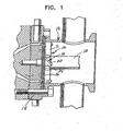
- the cutter hub and blade assembly 10 of the present invention is illustrated in its manner of use in Figure 1 and such structure is more specifically illustrated in U.S. Patents Nos. 4,123,207 and 4,251,198 with such disclosures being incorporated by reference in this application as if fully set forth herein.
- the underwater pelletizer includes a drive shaft 12 for driving the cutter hub and blade assembly 10 about the axis of the shaft 12 so that cutter blades 14 move along the face 16 of a die plate 18 within a water box 19 in a manner well known in the art.
- each cutter blade 14 includes a rectangular rigid metal body 20 having parallel opposed planar surfaces 22 and 24 and parallel inclined end edges 26 and 28 which also are parallel to each other to form cutting edges 30 and 32 at the opposite ends of the cutting blade 14.
- the cutting blade 14 is supported from a support arm 34 rigid with the cutter hub 11 which is provided with an inclined surface 36 against which one of the planar surfaces 22 or 24 is engaged with a tip end 30 or 32 engaging the die face 16.
- a fastener 38 such as a bolt, threaded into the support arm 34 secures the blade 14 in position and enables replacement thereof and also enables reversal of the blade so that either cutting edge 30 or 32 may be associated with the die face 16.
- the inclined or beveled edges 26 and 28 have a 45° angular relationship with respect to the planar surfaces 22 and 24, i.e., a 45° blade cutting edge angle.
- the angular relation between the planar surfaces 22 and 24 and the die face 16 is 75°, i.e., a 75° blade support angle.
- This arrangement orients the inclined or beveled edge 26 or 28 in a 30° relation to the die face 16, i.e., a 30° blade edge included angle.
- This 30° angle results in only the tip end of cutting edges 30 or 32 initially coming into engagement with the die face 16 as illustrated in Figure 2 .
- a blade edge included angle of at least about 20° is believed to result in faster blade grinding when seating new blades 14 to the die face 16 inasmuch as the tip ends of cutting edges 30 and 32 will more quickly seat against the die face 16.
- the prior art illustrated in Figure 4 includes a cutter blade 44 having beveled or inclined edges 46 in a 45° relation to the blade 44, or blade cutting edge angle of 45°.
- the blade is angled at 49° in relation to the die face, or a blade support angle of 49°, leaving a blade edge included angle of 4°, which requires a much longer grinding operation to seat against the die face.
- conventional assemblies with the blade support angle on the cutter hub at 30°, and the blade cutting edge angle also at 30° even more grinding is required to seat the blade against the die face.
- the prior art illustrated in Figure 5 includes a separation body or blade 54 which is perpendicular to the die face.
- This blade 54 also requires substantial grinding in order to seat against the die face and will introduce a pinching action in relation to the extruded strand when cutting through the strand to form a pellet.
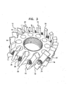
- the 60° - 79° steep blade support angle of this invention especially the preferred about 75° angle as illustrated in Figures 2 and 3 , provides a cleaner cut than the perpendicular blade illustrated in Figure 5 , in view of the flat peripheral edge engagement with the die face in the perpendicular arrangement.
- the steep blade support angle coupled with a 40° - 50° blade cutting edge angle, and an at least 20° blade edge included angle provides a slicing action due to a slightly angled blade surface cutting the extruded strand and removing the cut pellet.
Landscapes
- Engineering & Computer Science (AREA)
- Mechanical Engineering (AREA)
- Processing And Handling Of Plastics And Other Materials For Molding In General (AREA)
Claims (10)
- Ensemble (10) constitué par un porte-lames et une lame pour un granulateur sous eau, dans lequel du polymère fondu est extrudé sous forme de joncs à travers des orifices dans une plaque filière (18) avec une face frontale de filière (16), l'ensemble comprenant un porte-lames (11) rotatif, une multitude de bras supports (34) radiaux sur le porte-lames (11) et une multitude de lames de coupe (14) montées sur les bras supports (34), chaque lame de coupe (14) comprenant des surfaces planes (22, 24) parallèles se faisant face qui sont associées à des arêtes d'extrémité (26, 28) inclinées ou en biseau parallèles se faisant face sous un angle d'inclinaison de 40° à 50° pour former des arêtes tranchantes (30, 32) aux extrémités opposées des lames de coupe (14), une des arêtes tranchantes (30) ou (32) pouvant être associée à la face frontale de filière (16), les lames de coupe (14) pouvant être montées sur les bras supports (34) du porte-lames (11) sous un angle aigu et pouvant se déplacer le long de la face frontale de filière (16) de telle sorte qu'un angle de support entre les surfaces planes (22, 24) et la face frontale de filière (16) est entre 60° et 79° et un angle inclus entre les arêtes d'extrémité (26, 28) et la face frontale de filière (16) est d'au moins 20°.
- Ensemble selon la revendication 1, dans lequel l'angle de support entre les surfaces planes (22, 24) et la face frontale de filière (16) est entre 72° et environ 76° et de manière particulièrement préférée de 75°.
- Ensemble selon l'une des revendications 1 ou 2, dans lequel les bras supports (34) possèdent une surface (36) inclinée et dans lequel les lames de coupe (14) sont logées dans les surfaces (36) inclinées sous un angle entre 60° et 79°, de préférence entre environ 72° et environ 76°.
- Ensemble selon l'une des revendications précédentes, dans lequel les arêtes d'extrémité (26, 28) inclinées ou en biseau ont une relation angulaire de 45° par rapport aux surfaces planes (22, 24).
- Ensemble selon l'une des revendications précédentes, dans lequel l'angle de support, l'angle d'inclinaison et l'angle inclus sont combinés pour fournir une coupe propre des granules et pour permettre un affûtage de lame plus rapide lorsque des nouvelles lames de coupe (14) sont placées sur la face frontale de filière (16).
- Ensemble selon l'une des revendications précédentes, dans lequel l'angle de support aigu permet qu'un plus grand nombre de lames de coupe soit porté par le porte-lames (11) et réduit le suivi de l'arête tranchante de lame (28) en direction du milieu du porte-lames (11) lorsque les arêtes tranchantes de lames (28) s'usent.
- Ensemble selon l'une des revendications précédentes, dans lequel les lames de coupe (14) sont en général rectangulaires avec une arête tranchante inclinée ou en biseau aux deux extrémités (26, 28) de telle sorte que les lames de coupe (14) peuvent être inversées dans les bras supports (34).
- Ensemble selon la revendication 1, dans lequel sur chacun de la multitude de bras supports (34) radiaux, une de la multitude de lames de coupe (14) est montée sur le porte-lames (11).
- Granulateur sous eau dans lequel du polymère fondu est extrudé sous forme de joncs à travers des orifices d'une plaque filière (18), comprenant un ensemble (10) constitué par un porte-lames et une lame selon l'une des revendications précédentes.
- Granulateur sous eau selon la revendication 9, dans lequel le matériau extrudé sortant dans des orifices dans la plaque filière (18) est coupé en faisant tourner un porte-lames (11) et des lames de coupe (14).
Priority Applications (1)
| Application Number | Priority Date | Filing Date | Title |
|---|---|---|---|
| PL05006925T PL1582327T3 (pl) | 2004-04-01 | 2005-03-30 | Zespół piasty oraz ostrza noża dla granulatora podwodnego |
Applications Claiming Priority (2)
| Application Number | Priority Date | Filing Date | Title |
|---|---|---|---|
| US55813404P | 2004-04-01 | 2004-04-01 | |
| US558134P | 2004-04-01 |
Publications (3)
| Publication Number | Publication Date |
|---|---|
| EP1582327A2 EP1582327A2 (fr) | 2005-10-05 |
| EP1582327A3 EP1582327A3 (fr) | 2005-10-12 |
| EP1582327B1 true EP1582327B1 (fr) | 2015-05-13 |
Family
ID=34886347
Family Applications (1)
| Application Number | Title | Priority Date | Filing Date |
|---|---|---|---|
| EP20050006925 Expired - Lifetime EP1582327B1 (fr) | 2004-04-01 | 2005-03-30 | Tête de coupe et ensemble de lames pour un dispositif de granulation sous eau |
Country Status (3)
| Country | Link |
|---|---|
| US (1) | US7318719B2 (fr) |
| EP (1) | EP1582327B1 (fr) |
| PL (1) | PL1582327T3 (fr) |
Families Citing this family (21)
| Publication number | Priority date | Publication date | Assignee | Title |
|---|---|---|---|---|
| EP1696586A1 (fr) * | 2005-02-28 | 2006-08-30 | Sony Deutschland GmbH | Procédé de transmission optique sans fil et système de transmission optique sans fils de données. |
| ITMO20050223A1 (it) | 2005-09-07 | 2007-03-08 | Sacmi | Apparati e metodi per prcessare dosi di materiale scorrevole |
| US7267540B2 (en) | 2006-01-26 | 2007-09-11 | Gala Industries, Inc. | Steep angle cutter hub with blunt edge blades |
| DE202007019511U1 (de) | 2007-06-25 | 2013-03-14 | Gala Industries, Inc. | Gerät zur Herstellung von Polymerpellets enthaltend flüchtige organische Stoffe und/oder flüchtige organische Stoffe erzeugendes Material |
| EP2008784B1 (fr) | 2007-06-25 | 2013-02-27 | Gala Industries, Inc. | Procédé et appareil pour produire des granules de polymère contenant des volatils et/ou un matériau générant un volatil |
| US8080196B2 (en) * | 2008-02-12 | 2011-12-20 | Gala Industries, Inc. | Method and apparatus to achieve crystallization of polymers utilizing multiple processing systems |
| US9259857B2 (en) | 2008-02-12 | 2016-02-16 | Gala Industries, Inc. | Method and apparatus to condition polymers utilizing multiple processing systems |
| US9815223B2 (en) | 2008-05-16 | 2017-11-14 | Gala Industries, Inc. | Method and device for extrusion of hollow pellets |
| US8834760B2 (en) | 2008-05-16 | 2014-09-16 | Gala Industries, Inc. | Method and device for extrusion of hollow pellets |
| US20100040716A1 (en) * | 2008-08-13 | 2010-02-18 | Fridley Michael A | Thermally insulated die plate assembly for underwater pelletizing and the like |
| EP2156923A1 (fr) | 2008-08-19 | 2010-02-24 | Borealis AG | Dispositif de sécurité pour le support d'un ensemble de pale |
| US9925694B2 (en) | 2009-02-24 | 2018-03-27 | Gala Industries, Inc. | Continuous bagging processes and systems |
| CA2752085C (fr) | 2009-02-24 | 2015-08-18 | Gala Industries, Inc. | Procedes et systemes d'ensachage continu |
| US20100323047A1 (en) * | 2009-06-17 | 2010-12-23 | Fridley Michael A | Solid one-piece cutter hub and blade combination |
| US8671647B2 (en) | 2009-06-22 | 2014-03-18 | Gala Industries, Inc. | Continuous pelletizing, drying and bagging systems with improved throughput |
| WO2015026758A1 (fr) | 2013-08-20 | 2015-02-26 | Gala Industries, Inc. | Systèmes et procédés pour auto-aligner un ensemble de moyeu de coupe |
| US12550905B2 (en) * | 2014-01-13 | 2026-02-17 | Formtec, Llc. | Flexible blade |
| BR112017015555B1 (pt) | 2015-01-21 | 2022-04-19 | Gala Industries, Inc | Sistemas e processos de ensacamento contínuo |
| CN112171281B (zh) * | 2020-09-23 | 2021-11-19 | 衡阳鸿大精密制造有限责任公司 | 一种钢管等距切割倒角一体机 |
| CN113306040A (zh) * | 2021-06-11 | 2021-08-27 | 王继立 | 一种塑料挤出造粒机用切粒装置 |
| CN119141718B (zh) * | 2024-11-12 | 2025-03-21 | 上海创都均城环保科技有限公司 | 一种塑料废物再生用水冷切粒装置 |
Citations (1)
| Publication number | Priority date | Publication date | Assignee | Title |
|---|---|---|---|---|
| US20030102395A1 (en) * | 2000-12-13 | 2003-06-05 | Christopher Wessling | Separation device for underwater pelletizer |
Family Cites Families (17)
| Publication number | Priority date | Publication date | Assignee | Title |
|---|---|---|---|---|
| US1027537A (en) | 1910-01-07 | 1912-05-28 | Silver Mfg Company | Feed-cutter. |
| US1525025A (en) | 1920-08-27 | 1925-02-03 | Sev Mills Co | Wool-cutting machine |
| US2739647A (en) | 1951-11-17 | 1956-03-27 | Coste Pierre Paul Henri | Machine for the production of granular material, more particularly for injection moulding machines |
| US3070835A (en) * | 1960-01-12 | 1963-01-01 | Standard Oil Co | Pump quenching of polymer solvent mixtures |
| CH408392A (de) | 1963-12-30 | 1966-02-28 | Buss Ag | Auffanggehäuse für Granuliermaschinen |
| NL6500527A (fr) | 1964-02-01 | 1965-08-02 | ||
| US3292212A (en) | 1964-05-27 | 1966-12-20 | Midland Ross Corp | Pelleting apparatus |
| US4123307A (en) | 1968-07-11 | 1978-10-31 | Lemelson Jerome H | Method for forming hollow shells by rotational casting and winding thereon |
| US3831482A (en) | 1969-03-10 | 1974-08-27 | Boehler & Co Ag Geb | Apparatus for cutting of fiber strands |
| US3753637A (en) | 1972-02-14 | 1973-08-21 | Midland Ross Corp | Cooled-cutter hot-die pelletizer |
| US3792950A (en) | 1972-09-08 | 1974-02-19 | Cumberland Eng Co | Pelletizing apparatus |
| US4179255A (en) * | 1978-03-13 | 1979-12-18 | E. I. Du Pont De Nemours And Company | Melt cutter apparatus |
| US4251198A (en) * | 1979-04-27 | 1981-02-17 | Gala Industries, Inc. | Cutter hub with replaceable knife blades for underwater pelletizer |
| JPS576713A (en) | 1980-06-14 | 1982-01-13 | Matsushita Electric Works Ltd | Extrusion granulator for synthetic resin molding material |
| US5017119A (en) | 1990-04-03 | 1991-05-21 | Lauri Tokoi | Cutting means for underwater pelletizer |
| US5624688A (en) * | 1995-10-12 | 1997-04-29 | Gala Industries, Inc. | Self-aligning cutter hub |
| JP2905472B2 (ja) | 1997-03-04 | 1999-06-14 | 株式会社神戸製鋼所 | 水中カット造粒装置とその装置に使用するナイフ、並びに、そのナイフを用いた水中カット造粒方法 |
-
2005
- 2005-03-30 US US11/092,760 patent/US7318719B2/en not_active Expired - Lifetime
- 2005-03-30 EP EP20050006925 patent/EP1582327B1/fr not_active Expired - Lifetime
- 2005-03-30 PL PL05006925T patent/PL1582327T3/pl unknown
Patent Citations (1)
| Publication number | Priority date | Publication date | Assignee | Title |
|---|---|---|---|---|
| US20030102395A1 (en) * | 2000-12-13 | 2003-06-05 | Christopher Wessling | Separation device for underwater pelletizer |
Also Published As
| Publication number | Publication date |
|---|---|
| EP1582327A3 (fr) | 2005-10-12 |
| US7318719B2 (en) | 2008-01-15 |
| US20050220920A1 (en) | 2005-10-06 |
| PL1582327T3 (pl) | 2015-10-30 |
| EP1582327A2 (fr) | 2005-10-05 |
Similar Documents
| Publication | Publication Date | Title |
|---|---|---|
| EP1582327B1 (fr) | Tête de coupe et ensemble de lames pour un dispositif de granulation sous eau | |
| CN101405114B (zh) | 具有钝刃刀片的大角度切割器轮毂 | |
| US4251198A (en) | Cutter hub with replaceable knife blades for underwater pelletizer | |
| EP2012982B1 (fr) | Dispositif pour découper des pommes de terre ou autres légumes similaires | |
| US5284433A (en) | Spring-loaded self-adjusting melt cutter | |
| US5017119A (en) | Cutting means for underwater pelletizer | |
| KR101302574B1 (ko) | 플라스틱 멜트에서 입자상 그레인을 제조하는 장치 | |
| JP6718446B2 (ja) | 取り外し可能な刃を有する造粒ナイフ | |
| EP0821640B1 (fr) | Granulateur immerge | |
| US7425162B2 (en) | Cutting apparatus | |
| JP3497485B2 (ja) | 樹脂造粒機用カッタナイフ | |
| CN216572930U (zh) | 一种造粒机出料机构 | |
| CN222187435U (zh) | 一种刨削刀筒及带有该刨削刀筒的料理机 | |
| KR100469852B1 (ko) | 펠릿제조장치의 커터 | |
| SU1273257A1 (ru) | Устройство дл гранулировани термопластов |
Legal Events
| Date | Code | Title | Description |
|---|---|---|---|
| PUAI | Public reference made under article 153(3) epc to a published international application that has entered the european phase |
Free format text: ORIGINAL CODE: 0009012 |
|
| PUAL | Search report despatched |
Free format text: ORIGINAL CODE: 0009013 |
|
| AK | Designated contracting states |
Kind code of ref document: A2 Designated state(s): AT BE BG CH CY CZ DE DK EE ES FI FR GB GR HU IE IS IT LI LT LU MC NL PL PT RO SE SI SK TR |
|
| AX | Request for extension of the european patent |
Extension state: AL BA HR LV MK YU |
|
| AK | Designated contracting states |
Kind code of ref document: A3 Designated state(s): AT BE BG CH CY CZ DE DK EE ES FI FR GB GR HU IE IS IT LI LT LU MC NL PL PT RO SE SI SK TR |
|
| AX | Request for extension of the european patent |
Extension state: AL BA HR LV MK YU |
|
| 17P | Request for examination filed |
Effective date: 20060323 |
|
| AKX | Designation fees paid |
Designated state(s): AT BE BG CH CY CZ DE DK EE ES FI FR GB GR HU IE IS IT LI LT LU MC NL PL PT RO SE SI SK TR |
|
| 17Q | First examination report despatched |
Effective date: 20090319 |
|
| GRAJ | Information related to disapproval of communication of intention to grant by the applicant or resumption of examination proceedings by the epo deleted |
Free format text: ORIGINAL CODE: EPIDOSDIGR1 |
|
| GRAP | Despatch of communication of intention to grant a patent |
Free format text: ORIGINAL CODE: EPIDOSNIGR1 |
|
| GRAJ | Information related to disapproval of communication of intention to grant by the applicant or resumption of examination proceedings by the epo deleted |
Free format text: ORIGINAL CODE: EPIDOSDIGR1 |
|
| INTG | Intention to grant announced |
Effective date: 20141218 |
|
| GRAP | Despatch of communication of intention to grant a patent |
Free format text: ORIGINAL CODE: EPIDOSNIGR1 |
|
| INTC | Intention to grant announced (deleted) | ||
| INTG | Intention to grant announced |
Effective date: 20150115 |
|
| GRAS | Grant fee paid |
Free format text: ORIGINAL CODE: EPIDOSNIGR3 |
|
| GRAA | (expected) grant |
Free format text: ORIGINAL CODE: 0009210 |
|
| AK | Designated contracting states |
Kind code of ref document: B1 Designated state(s): AT BE BG CH CY CZ DE DK EE ES FI FR GB GR HU IE IS IT LI LT LU MC NL PL PT RO SE SI SK TR |
|
| REG | Reference to a national code |
Ref country code: GB Ref legal event code: FG4D |
|
| REG | Reference to a national code |
Ref country code: CH Ref legal event code: EP |
|
| REG | Reference to a national code |
Ref country code: IE Ref legal event code: FG4D |
|
| REG | Reference to a national code |
Ref country code: AT Ref legal event code: REF Ref document number: 726654 Country of ref document: AT Kind code of ref document: T Effective date: 20150615 |
|
| REG | Reference to a national code |
Ref country code: DE Ref legal event code: R096 Ref document number: 602005046542 Country of ref document: DE Effective date: 20150625 |
|
| REG | Reference to a national code |
Ref country code: NL Ref legal event code: T3 |
|
| REG | Reference to a national code |
Ref country code: LT Ref legal event code: MG4D |
|
| PG25 | Lapsed in a contracting state [announced via postgrant information from national office to epo] |
Ref country code: FI Free format text: LAPSE BECAUSE OF FAILURE TO SUBMIT A TRANSLATION OF THE DESCRIPTION OR TO PAY THE FEE WITHIN THE PRESCRIBED TIME-LIMIT Effective date: 20150513 Ref country code: PT Free format text: LAPSE BECAUSE OF FAILURE TO SUBMIT A TRANSLATION OF THE DESCRIPTION OR TO PAY THE FEE WITHIN THE PRESCRIBED TIME-LIMIT Effective date: 20150914 Ref country code: ES Free format text: LAPSE BECAUSE OF FAILURE TO SUBMIT A TRANSLATION OF THE DESCRIPTION OR TO PAY THE FEE WITHIN THE PRESCRIBED TIME-LIMIT Effective date: 20150513 Ref country code: LT Free format text: LAPSE BECAUSE OF FAILURE TO SUBMIT A TRANSLATION OF THE DESCRIPTION OR TO PAY THE FEE WITHIN THE PRESCRIBED TIME-LIMIT Effective date: 20150513 |
|
| REG | Reference to a national code |
Ref country code: PL Ref legal event code: T3 |
|
| PG25 | Lapsed in a contracting state [announced via postgrant information from national office to epo] |
Ref country code: BG Free format text: LAPSE BECAUSE OF FAILURE TO SUBMIT A TRANSLATION OF THE DESCRIPTION OR TO PAY THE FEE WITHIN THE PRESCRIBED TIME-LIMIT Effective date: 20150813 Ref country code: GR Free format text: LAPSE BECAUSE OF FAILURE TO SUBMIT A TRANSLATION OF THE DESCRIPTION OR TO PAY THE FEE WITHIN THE PRESCRIBED TIME-LIMIT Effective date: 20150814 Ref country code: IS Free format text: LAPSE BECAUSE OF FAILURE TO SUBMIT A TRANSLATION OF THE DESCRIPTION OR TO PAY THE FEE WITHIN THE PRESCRIBED TIME-LIMIT Effective date: 20150913 |
|
| PG25 | Lapsed in a contracting state [announced via postgrant information from national office to epo] |
Ref country code: EE Free format text: LAPSE BECAUSE OF FAILURE TO SUBMIT A TRANSLATION OF THE DESCRIPTION OR TO PAY THE FEE WITHIN THE PRESCRIBED TIME-LIMIT Effective date: 20150513 Ref country code: DK Free format text: LAPSE BECAUSE OF FAILURE TO SUBMIT A TRANSLATION OF THE DESCRIPTION OR TO PAY THE FEE WITHIN THE PRESCRIBED TIME-LIMIT Effective date: 20150513 |
|
| REG | Reference to a national code |
Ref country code: DE Ref legal event code: R097 Ref document number: 602005046542 Country of ref document: DE |
|
| PG25 | Lapsed in a contracting state [announced via postgrant information from national office to epo] |
Ref country code: SK Free format text: LAPSE BECAUSE OF FAILURE TO SUBMIT A TRANSLATION OF THE DESCRIPTION OR TO PAY THE FEE WITHIN THE PRESCRIBED TIME-LIMIT Effective date: 20150513 Ref country code: RO Free format text: LAPSE BECAUSE OF NON-PAYMENT OF DUE FEES Effective date: 20150513 |
|
| PLBE | No opposition filed within time limit |
Free format text: ORIGINAL CODE: 0009261 |
|
| STAA | Information on the status of an ep patent application or granted ep patent |
Free format text: STATUS: NO OPPOSITION FILED WITHIN TIME LIMIT |
|
| 26N | No opposition filed |
Effective date: 20160216 |
|
| PGFP | Annual fee paid to national office [announced via postgrant information from national office to epo] |
Ref country code: NL Payment date: 20160321 Year of fee payment: 12 Ref country code: CZ Payment date: 20160330 Year of fee payment: 12 |
|
| PG25 | Lapsed in a contracting state [announced via postgrant information from national office to epo] |
Ref country code: SI Free format text: LAPSE BECAUSE OF FAILURE TO SUBMIT A TRANSLATION OF THE DESCRIPTION OR TO PAY THE FEE WITHIN THE PRESCRIBED TIME-LIMIT Effective date: 20150513 |
|
| PG25 | Lapsed in a contracting state [announced via postgrant information from national office to epo] |
Ref country code: MC Free format text: LAPSE BECAUSE OF FAILURE TO SUBMIT A TRANSLATION OF THE DESCRIPTION OR TO PAY THE FEE WITHIN THE PRESCRIBED TIME-LIMIT Effective date: 20150513 Ref country code: LU Free format text: LAPSE BECAUSE OF FAILURE TO SUBMIT A TRANSLATION OF THE DESCRIPTION OR TO PAY THE FEE WITHIN THE PRESCRIBED TIME-LIMIT Effective date: 20160330 |
|
| REG | Reference to a national code |
Ref country code: CH Ref legal event code: PL |
|
| GBPC | Gb: european patent ceased through non-payment of renewal fee |
Effective date: 20160330 |
|
| REG | Reference to a national code |
Ref country code: AT Ref legal event code: UEP Ref document number: 726654 Country of ref document: AT Kind code of ref document: T Effective date: 20150513 |
|
| REG | Reference to a national code |
Ref country code: IE Ref legal event code: MM4A |
|
| REG | Reference to a national code |
Ref country code: FR Ref legal event code: ST Effective date: 20161130 |
|
| PG25 | Lapsed in a contracting state [announced via postgrant information from national office to epo] |
Ref country code: GB Free format text: LAPSE BECAUSE OF NON-PAYMENT OF DUE FEES Effective date: 20160330 Ref country code: CH Free format text: LAPSE BECAUSE OF NON-PAYMENT OF DUE FEES Effective date: 20160331 Ref country code: FR Free format text: LAPSE BECAUSE OF NON-PAYMENT OF DUE FEES Effective date: 20160331 Ref country code: IE Free format text: LAPSE BECAUSE OF NON-PAYMENT OF DUE FEES Effective date: 20160330 Ref country code: LI Free format text: LAPSE BECAUSE OF NON-PAYMENT OF DUE FEES Effective date: 20160331 |
|
| PG25 | Lapsed in a contracting state [announced via postgrant information from national office to epo] |
Ref country code: SE Free format text: LAPSE BECAUSE OF FAILURE TO SUBMIT A TRANSLATION OF THE DESCRIPTION OR TO PAY THE FEE WITHIN THE PRESCRIBED TIME-LIMIT Effective date: 20150513 |
|
| PG25 | Lapsed in a contracting state [announced via postgrant information from national office to epo] |
Ref country code: PL Free format text: LAPSE BECAUSE OF NON-PAYMENT OF DUE FEES Effective date: 20160330 |
|
| PG25 | Lapsed in a contracting state [announced via postgrant information from national office to epo] |
Ref country code: CZ Free format text: LAPSE BECAUSE OF NON-PAYMENT OF DUE FEES Effective date: 20170330 |
|
| REG | Reference to a national code |
Ref country code: NL Ref legal event code: MM Effective date: 20170401 |
|
| PG25 | Lapsed in a contracting state [announced via postgrant information from national office to epo] |
Ref country code: NL Free format text: LAPSE BECAUSE OF NON-PAYMENT OF DUE FEES Effective date: 20170401 |
|
| PG25 | Lapsed in a contracting state [announced via postgrant information from national office to epo] |
Ref country code: CY Free format text: LAPSE BECAUSE OF FAILURE TO SUBMIT A TRANSLATION OF THE DESCRIPTION OR TO PAY THE FEE WITHIN THE PRESCRIBED TIME-LIMIT Effective date: 20150513 Ref country code: HU Free format text: LAPSE BECAUSE OF FAILURE TO SUBMIT A TRANSLATION OF THE DESCRIPTION OR TO PAY THE FEE WITHIN THE PRESCRIBED TIME-LIMIT; INVALID AB INITIO Effective date: 20050330 |
|
| PGFP | Annual fee paid to national office [announced via postgrant information from national office to epo] |
Ref country code: AT Payment date: 20180322 Year of fee payment: 14 |
|
| REG | Reference to a national code |
Ref country code: AT Ref legal event code: MM01 Ref document number: 726654 Country of ref document: AT Kind code of ref document: T Effective date: 20190330 |
|
| PG25 | Lapsed in a contracting state [announced via postgrant information from national office to epo] |
Ref country code: AT Free format text: LAPSE BECAUSE OF NON-PAYMENT OF DUE FEES Effective date: 20190330 |
|
| PGFP | Annual fee paid to national office [announced via postgrant information from national office to epo] |
Ref country code: BE Payment date: 20200319 Year of fee payment: 16 |
|
| REG | Reference to a national code |
Ref country code: BE Ref legal event code: MM Effective date: 20210331 |
|
| PG25 | Lapsed in a contracting state [announced via postgrant information from national office to epo] |
Ref country code: BE Free format text: LAPSE BECAUSE OF NON-PAYMENT OF DUE FEES Effective date: 20210331 |
|
| PGFP | Annual fee paid to national office [announced via postgrant information from national office to epo] |
Ref country code: DE Payment date: 20240320 Year of fee payment: 20 |
|
| PGFP | Annual fee paid to national office [announced via postgrant information from national office to epo] |
Ref country code: IT Payment date: 20240329 Year of fee payment: 20 |
|
| PG25 | Lapsed in a contracting state [announced via postgrant information from national office to epo] |
Ref country code: TR Free format text: LAPSE BECAUSE OF NON-PAYMENT OF DUE FEES Effective date: 20160330 |
|
| REG | Reference to a national code |
Ref country code: DE Ref legal event code: R071 Ref document number: 602005046542 Country of ref document: DE |