EP1582638A2 - Inspektionsschaft mit Geruchverschluss - Google Patents
Inspektionsschaft mit Geruchverschluss Download PDFInfo
- Publication number
- EP1582638A2 EP1582638A2 EP05005451A EP05005451A EP1582638A2 EP 1582638 A2 EP1582638 A2 EP 1582638A2 EP 05005451 A EP05005451 A EP 05005451A EP 05005451 A EP05005451 A EP 05005451A EP 1582638 A2 EP1582638 A2 EP 1582638A2
- Authority
- EP
- European Patent Office
- Prior art keywords
- discharge
- collection
- inspection shaft
- liquids
- partition walls
- Prior art date
- Legal status (The legal status is an assumption and is not a legal conclusion. Google has not performed a legal analysis and makes no representation as to the accuracy of the status listed.)
- Withdrawn
Links
Images


Classifications
-
- E—FIXED CONSTRUCTIONS
- E03—WATER SUPPLY; SEWERAGE
- E03F—SEWERS; CESSPOOLS
- E03F5/00—Sewerage structures
- E03F5/04—Gullies inlets, road sinks, floor drains with or without odour seals or sediment traps
- E03F5/0401—Gullies for use in roads or pavements
- E03F5/0405—Gullies for use in roads or pavements with an odour seal
-
- E—FIXED CONSTRUCTIONS
- E03—WATER SUPPLY; SEWERAGE
- E03F—SEWERS; CESSPOOLS
- E03F5/00—Sewerage structures
- E03F5/04—Gullies inlets, road sinks, floor drains with or without odour seals or sediment traps
- E03F5/0401—Gullies for use in roads or pavements
- E03F5/0405—Gullies for use in roads or pavements with an odour seal
- E03F5/0406—Gullies for use in roads or pavements with an odour seal the odour seal being easily accessible for cleaning
Definitions
- the present invention refers to an inspection shaft for the collection and discharge of liquids or the like.
- This inspection shaft is carried out in such a way as to include also a sector that acts as a running trap.
- the said inspection shafts show a cubic shape and are provided with discharge holes for the discharge of the collected liquids.
- the discharge holes are positioned in the upper part of the wall that delimits the collecting chamber of the liquids. The presence of a certain quantity of liquid in the lower part of the collecting chamber is necessary to obtain a trap effect.
- the present invention proposes to carry out a monobloc preferably but not necessarily in a plastic material, which removes the drawbacks of the other inspection shafts and, as an advantage, allows a water discharge in very low levels and immediately above its lower base.
- the inspection shaft for the collection and discharge of water is characterized in that it comprises a basin or containing element which collects and discharges water or other liquids; the body or containing element is provided with lateral shoulders which show borders which support, partially, an extractable cover; partition walls are arranged between the said lateral shoulders; the height of the partition walls is shorter than the height of the shoulders and the partition walls form at least a liquid collection sector and a liquid discharge sector.
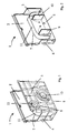
- number 1 denotes an inspection shaft for the inspection, collection and discharge of liquids, in particular rain-water.
- Said inspection shaft 1 comprises a monobloc which is preferably carried out in a plastic material.
- the monobloc is defined by lateral walls 2, 3, 4 and 5 and a base 6.
- the lateral walls 2, 3, 4 and 5 and base 6 form collection and discharge sectors for the liquids.
- Essentially arcuated shoulders 7 and 8 are disposed inside the inspection shaft and are attached to said walls. More precisely, the shoulders are disposed longitudinally onto said walls.
- Two partition walls 9 and 10 are connected to the free sides and form a unit with the shoulders 7 and 8.
- the height of the partition walls 9 and 10 is shorter than the height of the shoulders 7 and 8 and delimit three separate sectors A, B and C.
- the sectors A and C are to collect the liquid while the sector B is to discharge the liquid.
- a cover 11 having the same shape of the walls is supported by the borders of the shoulders 7 and 8.
- the cover 11 extends laterally to a certain extent in the collection sectors A and C but always remains under the height of the partition walls 9 and 10.
- the particular combination and arrangement of the cover and partition walls gives the inspection shaft according to the present invention an innovative appearance since a trap effect is obtained to prevent a return of the stink, there being the possibility of discharging the fluid or liquid at a lowest level, namely, at the level of the base 6.
- joint holes 12 for the insertion of upper tubes for the collection of water and joint holes 13 for the insertion of lower tubes for the discharge of water.
- the rain-water or the liquid coming from the joint hole 12 or upper grill (non represented) reaches the inside of the shaft and is canalized through the cover 11 towards the collection sectors A and C.
- the collected water goes up by flowing under the cover 11 and over the walls 9 and 10 and overflows in the discharge sector B. Once the liquid has reached the discharge sector B, the liquid is discharged in 13 and the sector B remains completely free.
- the said residual water is included between walls 9 and 10 and is also included between the end parts of cover 11.
- the said residual water permits to obtain a trap or siphon effect so that the stinking miasmas that return from sector B are stopped in sector B itself and can not reach sectors A and C.
- inspection shaft 1 Another advantage of the inspection shaft 1 is the presence of cover 11 which is positioned under pressure on shoulders 7 and 8 and may be removed whenever it is necessary. When cover 11 is removed, it is also possible to perfectly clean the inside of the inspection shaft.
- box of the inspection shaft 1 always shows a shape that permits a rapid and safe connection of channels and ducts of different size.
Landscapes
- Health & Medical Sciences (AREA)
- Life Sciences & Earth Sciences (AREA)
- Engineering & Computer Science (AREA)
- Hydrology & Water Resources (AREA)
- Public Health (AREA)
- Water Supply & Treatment (AREA)
- Catching Or Destruction (AREA)
- Food-Manufacturing Devices (AREA)
- Extraction Or Liquid Replacement (AREA)
Applications Claiming Priority (2)
| Application Number | Priority Date | Filing Date | Title |
|---|---|---|---|
| ITVR20040045 ITVR20040045A1 (it) | 2004-04-02 | 2004-04-02 | Pozzetto di ispezione con sifone per la raccolta ed il deflusso di liquidi. |
| ITVR20040045 | 2004-04-02 |
Publications (2)
| Publication Number | Publication Date |
|---|---|
| EP1582638A2 true EP1582638A2 (de) | 2005-10-05 |
| EP1582638A3 EP1582638A3 (de) | 2005-10-26 |
Family
ID=34878887
Family Applications (1)
| Application Number | Title | Priority Date | Filing Date |
|---|---|---|---|
| EP05005451A Withdrawn EP1582638A3 (de) | 2004-04-02 | 2005-03-14 | Inspektionsschaft mit Geruchverschluss |
Country Status (2)
| Country | Link |
|---|---|
| EP (1) | EP1582638A3 (de) |
| IT (1) | ITVR20040045A1 (de) |
Cited By (2)
| Publication number | Priority date | Publication date | Assignee | Title |
|---|---|---|---|---|
| EP2532795A3 (de) * | 2011-02-15 | 2015-10-21 | Jimten, S.A. | Abflussrinne mit reduzierter Höhe mit eingebautem Geruchsverschluss |
| DE102018121292A1 (de) * | 2018-08-31 | 2020-03-05 | ACO Severin Ahlmann GmbH & Co Kommanditgesellschaft | Entwässerungsschacht und Entwässerungssystem |
Family Cites Families (6)
| Publication number | Priority date | Publication date | Assignee | Title |
|---|---|---|---|---|
| CH119180A (de) * | 1926-06-07 | 1927-03-01 | Erben Jules Webers | Sinkkasten. |
| GB320199A (en) * | 1928-09-04 | 1929-10-10 | David Thomas | Improvements in and relating to water gullies |
| CA1099183A (en) * | 1977-08-31 | 1981-04-14 | Kurt S. B. Ericson | Waste water outlet sanitary plant comprising a siphon |
| DE2837967C2 (de) * | 1978-08-31 | 1982-10-21 | Bernhard 8071 Lenting Kessel | Wasserablaufbehälter |
| GB2134940B (en) * | 1982-12-15 | 1986-03-19 | Michael Robert Jupp | Drainage gully trap |
| DE20308922U1 (de) * | 2003-06-07 | 2003-11-20 | Meier, Karl, 37619 Pegestorf | Rückstausperranlage bestehend aus einer Rohrbogen-Rückstausperre mit Kugelverschluss, sowie höhenverstellbarer Bodenentwässerung |
-
2004
- 2004-04-02 IT ITVR20040045 patent/ITVR20040045A1/it unknown
-
2005
- 2005-03-14 EP EP05005451A patent/EP1582638A3/de not_active Withdrawn
Cited By (5)
| Publication number | Priority date | Publication date | Assignee | Title |
|---|---|---|---|---|
| EP2532795A3 (de) * | 2011-02-15 | 2015-10-21 | Jimten, S.A. | Abflussrinne mit reduzierter Höhe mit eingebautem Geruchsverschluss |
| DE102018121292A1 (de) * | 2018-08-31 | 2020-03-05 | ACO Severin Ahlmann GmbH & Co Kommanditgesellschaft | Entwässerungsschacht und Entwässerungssystem |
| AT521583A3 (de) * | 2018-08-31 | 2023-12-15 | Aco Ahlmann Se & Co Kg | Entwässerungsschacht und Entwässerungssystem |
| AT521583B1 (de) * | 2018-08-31 | 2024-08-15 | Aco Ahlmann Se & Co Kg | Entwässerungsschacht und Entwässerungssystem |
| NO349074B1 (no) * | 2018-08-31 | 2025-09-15 | Aco Severin Ahlmann Gmbh & Co Kg | Dreneringssjakt og dreneringssystem |
Also Published As
| Publication number | Publication date |
|---|---|
| ITVR20040045A1 (it) | 2004-07-02 |
| EP1582638A3 (de) | 2005-10-26 |
Similar Documents
| Publication | Publication Date | Title |
|---|---|---|
| EP3215684B1 (de) | Abflussanordnung, abflusskörper zur verwendung in der anordnung und geruchsverschluss zur verwendung in solch einer anordnung | |
| EP1577452B2 (de) | Entwässerungsrinne | |
| EP1854929B1 (de) | Abfluss | |
| KR20090127911A (ko) | 플로어 드레인 | |
| JP2003328418A (ja) | 排水配管 | |
| JP7041593B2 (ja) | 防臭ワン | |
| KR102348207B1 (ko) | 부유물질과 고형물질의 배출에 전문화된 오수탱크 시스템 | |
| KR100538651B1 (ko) | 오수받이 장치 | |
| KR100882439B1 (ko) | 악취 역류 방지용 배수 트렌치 | |
| JP7236240B2 (ja) | シンク | |
| JP3679971B2 (ja) | ショーケースの排水装置 | |
| JP2834066B2 (ja) | 円形オイル阻集器 | |
| KR102031231B1 (ko) | 이중구조를 갖는 배수구 | |
| KR200489534Y1 (ko) | 거름부재를 갖춘 배수 트랜치 | |
| JPS6332203Y2 (de) | ||
| JP2005221221A (ja) | 製氷機の排水構造 | |
| KR200218248Y1 (ko) | 집수정 | |
| CN218970462U (zh) | 一种建筑排水构造 | |
| KR200446872Y1 (ko) | 하수구의 배출구조 | |
| JP2604558B2 (ja) | 円形オイル阻集器 | |
| KR20250085966A (ko) | 세탁실 전용 플로우 드레인 | |
| AU747968B2 (en) | Self cleaning aquarium system | |
| EP1582638A3 (de) | Inspektionsschaft mit Geruchverschluss | |
| JP2503859Y2 (ja) | 作業室用排水桝 | |
| JP6074187B2 (ja) | グリース阻集システム |
Legal Events
| Date | Code | Title | Description |
|---|---|---|---|
| PUAI | Public reference made under article 153(3) epc to a published international application that has entered the european phase |
Free format text: ORIGINAL CODE: 0009012 |
|
| PUAL | Search report despatched |
Free format text: ORIGINAL CODE: 0009013 |
|
| AK | Designated contracting states |
Kind code of ref document: A2 Designated state(s): AT BE BG CH CY CZ DE DK EE ES FI FR GB GR HU IE IS IT LI LT LU MC NL PL PT RO SE SI SK TR |
|
| AX | Request for extension of the european patent |
Extension state: AL BA HR LV MK YU |
|
| AK | Designated contracting states |
Kind code of ref document: A3 Designated state(s): AT BE BG CH CY CZ DE DK EE ES FI FR GB GR HU IE IS IT LI LT LU MC NL PL PT RO SE SI SK TR |
|
| AX | Request for extension of the european patent |
Extension state: AL BA HR LV MK YU |
|
| AKX | Designation fees paid | ||
| REG | Reference to a national code |
Ref country code: DE Ref legal event code: 8566 |
|
| STAA | Information on the status of an ep patent application or granted ep patent |
Free format text: STATUS: THE APPLICATION IS DEEMED TO BE WITHDRAWN |
|
| 18D | Application deemed to be withdrawn |
Effective date: 20060426 |