EP1582664A2 - Verriegelungsvorrichtung mit Drucktasten - Google Patents
Verriegelungsvorrichtung mit Drucktasten Download PDFInfo
- Publication number
- EP1582664A2 EP1582664A2 EP05290686A EP05290686A EP1582664A2 EP 1582664 A2 EP1582664 A2 EP 1582664A2 EP 05290686 A EP05290686 A EP 05290686A EP 05290686 A EP05290686 A EP 05290686A EP 1582664 A2 EP1582664 A2 EP 1582664A2
- Authority
- EP
- European Patent Office
- Prior art keywords
- housing
- slider
- gear
- house
- unlocking
- Prior art date
- Legal status (The legal status is an assumption and is not a legal conclusion. Google has not performed a legal analysis and makes no representation as to the accuracy of the status listed.)
- Withdrawn
Links
Images


Classifications
-
- E—FIXED CONSTRUCTIONS
- E05—LOCKS; KEYS; WINDOW OR DOOR FITTINGS; SAFES
- E05B—LOCKS; ACCESSORIES THEREFOR; HANDCUFFS
- E05B37/00—Permutation or combination locks; Puzzle locks
- E05B37/16—Permutation or combination locks; Puzzle locks with two or more push or pull knobs, slides, or the like
-
- E—FIXED CONSTRUCTIONS
- E05—LOCKS; KEYS; WINDOW OR DOOR FITTINGS; SAFES
- E05B—LOCKS; ACCESSORIES THEREFOR; HANDCUFFS
- E05B53/00—Operation or control of locks by mechanical transmissions, e.g. from a distance
- E05B53/008—Operation or control of locks by mechanical transmissions, e.g. from a distance by planetary gears
-
- Y—GENERAL TAGGING OF NEW TECHNOLOGICAL DEVELOPMENTS; GENERAL TAGGING OF CROSS-SECTIONAL TECHNOLOGIES SPANNING OVER SEVERAL SECTIONS OF THE IPC; TECHNICAL SUBJECTS COVERED BY FORMER USPC CROSS-REFERENCE ART COLLECTIONS [XRACs] AND DIGESTS
- Y10—TECHNICAL SUBJECTS COVERED BY FORMER USPC
- Y10T—TECHNICAL SUBJECTS COVERED BY FORMER US CLASSIFICATION
- Y10T70/00—Locks
- Y10T70/50—Special application
- Y10T70/5611—For control and machine elements
- Y10T70/5757—Handle, handwheel or knob
- Y10T70/5765—Rotary or swinging
- Y10T70/577—Locked stationary
- Y10T70/5783—Combination lock
- Y10T70/5788—Push pin or button
-
- Y—GENERAL TAGGING OF NEW TECHNOLOGICAL DEVELOPMENTS; GENERAL TAGGING OF CROSS-SECTIONAL TECHNOLOGIES SPANNING OVER SEVERAL SECTIONS OF THE IPC; TECHNICAL SUBJECTS COVERED BY FORMER USPC CROSS-REFERENCE ART COLLECTIONS [XRACs] AND DIGESTS
- Y10—TECHNICAL SUBJECTS COVERED BY FORMER USPC
- Y10T—TECHNICAL SUBJECTS COVERED BY FORMER US CLASSIFICATION
- Y10T70/00—Locks
- Y10T70/70—Operating mechanism
- Y10T70/7153—Combination
- Y10T70/7181—Tumbler type
- Y10T70/7198—Single tumbler set
- Y10T70/7215—Individually set sliding tumblers
- Y10T70/7226—Associated movable operator
Definitions
- the present invention relates to a device for pushbuttons which is for example used in doors and which is provided with a plurality of pushbuttons.
- pushbutton lock of the input type of a unlock code and that do not require a key.
- pushbutton locking devices of this type a plurality of pushbuttons on which are displayed different numbers or the like are retractably provided on a housing, and the push-button locking device is unlocked only when the buttons that coincide with the unlock code of these buttons have been pushed, see for example Japanese Patent No. 2638476 (page 3, Fig. 4).
- the devices for pushbutton lock of the technique prior art as described above include a actuating element for opening / closing a door, such as a door knob, which is fixed to turn on the outer side of the housing, a drive gear concentrically fixed inside the housing for the actuating element, and a plurality of rocker arms provided for each of the plurality of pushbuttons who are moving to the back side of the housing in accordance with the push operation of a corresponding push button.
- the pushbutton lock includes a mechanism for locking which comprises a flat slider forming stirrup, provided so as to be able to move in the direction orthogonal to the direction of movement of rockers inside the housing, in which protruding parts that can engage with the rockers are formed on the inner circumferential side, and a mechanism of motion transmission that converts, in a linear movement of the slider, the movement of rotation of the drive gear that turns into accompanying the rotation operation of the element actuation, the push-button locking device being kept in a locked state by engaging the protruding parts of the slide with rockers.
- a mechanism for locking which comprises a flat slider forming stirrup, provided so as to be able to move in the direction orthogonal to the direction of movement of rockers inside the housing, in which protruding parts that can engage with the rockers are formed on the inner circumferential side, and a mechanism of motion transmission that converts, in a linear movement of the slider, the movement of rotation of the drive gear that turns into accompanying the rotation operation of the
- Push-button locks of this type include a "restoration" button that allows restoration of erroneous operations including the erroneous push buttons.
- the locking device with push buttons of the present invention is characterized in that includes a housing, a plurality of pushbuttons retractably provided on the surface side before the housing, a plurality of tumblers of locking and non-locking, provided in the housing in correspondence of the pushbuttons, which are moved to the back side in the direction of the front to the back of the housing when a push button corresponding is operated by pushing, a slider provided in the housing so as to be able to move in the direction orthogonal to the direction of movement of the rockers, which is authorized to move in the unlocking direction to inside the housing only when the rockers unlocking are operated by pushing by via pushbuttons, an element actuating the opening / closing of the door provided rotating way on the front surface side of the housing, which comprises, in the housing, a gear of training arranged concentrically by relative to its center of rotation, and a mechanism to planetary gear, including the drive gear serving as a sun wheel, and gears planetary arranged in such a way that their range of rotation with respect to the solar wheel covers
- the slide is moved to the unlocking direction by a planetary gear mechanism comprising planetary gears arranged so that the range rotation relative to the solar wheel that serves of gearing gear partially overlaps the sliding range of the slide, which is different of the example described above of the prior art, the range of movement of the slider can be brought closer to the drive gear. It results that the distance between the drive gear and the slider can be reduced and it is possible to reduce the external dimensions of the housing.
- a recess exhaust disposed opposite the side of the gear drive is formed in the slider.
- the mechanism planetary gear lock device to previously mentioned push buttons includes a fixed frame provided in the housing which includes teeth fixed internals with which the sun wheel meshes with a a plurality of planetary gears meshing with the solar wheel and the inner teeth and rotate while turning on their own axes around the wheel solar, and a holding element that maintains the planetary gears turning to be able to turn on their own axes so as to rotate with the planetary gears, and includes a thrust portion which comes into abutment with the slider.
- the abutment portion abuts against the slider to move the slider into the unlocking direction when holding element rotates with the planetary gear around the wheel solar.
- the part stop is provided on a rotating frame comprising teeth that mesh with planetary gears at level around the planetary gears and where the slide is driven, according to the rotation of planetary gears and rotating frame in sequence by the operation of rotation of the sun wheel, by the stop of the abutment portion of the rotating frame, the slider can be driven with removal of the rattling at the party level meshing of the gear between the sun wheel and the stop portion, and the slider can be moved from regularly.
- the locking device with push buttons may further include pushing elements for return the rockers to the original position non-thrust, a restoration actuating body, including an implementation part to maintain the rockers in the pushed position, which are provided in the case to be able to move in the same direction that the slider, and a cam element, provided concentrically in the housing relative to the center of rotation of the actuating element, which acts that the actuating body of restoration according to to the operation of rotation of the actuating element.
- cam surfaces that come into abutment and act on the body Restoration actuation is provided in such a way symmetrical in the cam element.
- the cam element can have a different application on pushbutton locks two types in which the actuating element is rotated to the left or right and, consequently, because of this shared use component parts of different push button lock, you can get a general cost reduction.
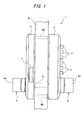
- Fig. 1 is a side view illustrating the state fitted with a push-button locking device according to an embodiment of this invention.
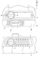
- Figs. 2 (a) and 2 (b) are external views taken from the side outside the house and, respectively on the inside of the house, the push button locking device mentioned previously.
- Fig. 3 is a vertical cross-section at larger scale illustrating the constitution of the main portion of the inner part of the housing shown in FIG. 1.
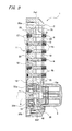
- Fig. 4 is a plan view on a larger scale the constitution of the main portion of the game internal housing mentioned previously taken from the side to inside the house.
- Fig. 5 is a cross section taken along of the line V-V of FIG. 4.
- Figs. 6 (a) and 6 (b) are front views of unlocking and non-unlocking rocker arms shown in FIG. 5.
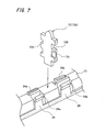
- Fig. 7 is a perspective view illustrating the relationship between the rockers mentioned above and the restoration actuating body shown at the Fig 5.
- Fig. 8 is an exploded view of the elements actuator, the rotating body and the mechanism planetary gear shown in FIG. 3.
- Fig. 9 (a) is a plan view of the guide gearing provided in the gear mechanism aforementioned planetary taken from the outside at home
- Figs. 9 (b) and (c) are sections taken along the lines IX b - IX b and IX c - IX c of FIG. 9a.
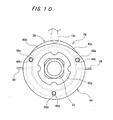
- Fig. 10 is a plan view to larger rotating body scale mentioned previously taken from the side inside the house.
- Fig. 1 is a side view that illustrates the state mounted pushbutton lock device belonging to a first embodiment of the present invention
- 2 (a) and 2 (b) are external views of the pushbutton lock taken from the side inside the house and, respectively, on the outside side of the house.
- Fig. 1 and Figs. 2 (a) and 2 (b) show the pushbutton locking device 1 of the first embodiment which comprises a housing 2 mounted on the side outside the house of a door D and a decorative cover 3 attached to the side to inside the house of the door D.
- a plurality to As an example, a total of 12 pushbuttons 4 arranged in two rows of six, and a button 5 side outside at home to open and close the door D from outside, are provided in the housing 2.
- the decorative covering 3 includes a button 6 interior side at home to open and close the door D from the inside, as well as a pin element in plate shape 7 which protrudes towards the side of the frame DW gate from an opening portion formed on the side of the decorative cover 3.
- the housing 2 and the decorative covering 3 are fixed in corresponding positions on the inside and the outside of the door D by fixing bolts 8a, 8b, which pass through the door D from the inside side of the House.
- Button 5 on the outside side of the house and the button 6 on the side inside the house include finger parts 5a and 6a configured to protrude respectively from the side outside the house and the side to inside the house and which are so fixed rotating on the corresponding housing 2 and the 3.
- buttons 5, 6, which are arranged concentrically on the side to inside the house and the outside side of the house, are respectively connected to a first side end and at the other end side of a tree lamb 9 drive arranged to pass through the
- the bolt element 7 is connected to the interior of the decorative covering 3 to the tree 9 and drive shaft, rotating the shaft lamb 9 training in response to the operation drive button 5 on the outside side of the house and button 6 on the side inside the house, the bolt member 7 is pulled towards the inner side of the 9. Because of this, the element of 7 is moved from an engaged state (shown at Fig.
- button 5 on the outside side from the house and the 6 button on the inside side of the house is configured from an actuating element opening / closing of which the rotation operation is locked by the locking mechanism described more away and, as described later, it includes a body rotating and a drive gear disposed of concentrically in relation to its center of rotation. Due to the obstacle to the rotation of the tree training 9 and the accompanying movement of the bolt element 7 due to locking by the locking mechanism mentioned previously of the operation of rotation of the button 5 outer side to the house, the push-button lock 1 maintains the locked state of the door D.
- the button 6 inside the house which is configured so that the drive shaft of pin 9 and the pin member 7 are rotated in sequence whatever the operating state of the mechanism of locking, allows the establishment of the door D to be in the locked state is in the unlocked state, as required.
- the aforementioned plurality of pushbuttons 4 which, as we can see by referring to the Fig. 3 to 5, are retractably provided on the side of the front surface of the housing 2, is configured to such as to allow a numerical entry of a code unlocking that produces the unlocked status of the pushbutton locking device 1.
- numbers (0-9) and alphabetical letters (A, B, 7) that came in the form of an unlock code accompanying the pushing operation of the pushbuttons, are displayed in the front surface of the housing 2 on or near each push button.
- Rocker arms 12 are also provided to be able to to move in the housing 2 in the direction of the front to the rear of it (direction from right to the left in FIG. 3) are connected to the pushbuttons 4.
- Rocker arms 12 are configured to be moved from the non-thrust position inside from the housing 2 to the pushing position at the rear side in the direction of the front to the back of the housing 2 in response to the push operation of corresponding pushbuttons 4, and to be maintained in the pushing position.
- rocker arms 12 include unlocking rockers 12a which prepare the unlock code mentioned above and non-unlocking rockers 12b for maintain the locked state of the locking mechanism 11 and, using the locking device to pushbuttons 1, the locked state produced by the lock mechanism 11 is unlocked only when an unlock code set in advance is correctly introduced via pushbuttons, that is to say only when the rockers 12a are moved to the position of pushing via the pushbuttons 4.
- the locking mechanism 11 mentioned previously, as shown in FIGS. 3 to 5, includes a guide groove 14 for the actuating body of restoration 13 stretching in the direction longitudinal housing 2 (direction from top to bottom of FIG. 3) which is formed centrally in the direction of the width, and a base plate 16 having a plurality of insertion holes 15 formed rockers at both sides of the groove 14.
- the plate base 16 is removably attached to a body main 2a of the housing 2 by means of bolts 30a, 30b. It should be noted that the holes in which these bolts 30a, 30b are screwed are formed in parallel positions in the direction of the width of the housing with holes 2a1, 2a2 through which pass the fixing bolts 8a and 8b.
- the locking mechanism 11 further comprises a slider 17 slidable on the upper side housing 2 in the longitudinal direction (side upper part of FIG. 3) in relation to the plate of base 16 and which is slidably disposed on the side outside the house of the base plate 16, a planetary gear mechanism 18 which serves as a displacement transmission mechanism to move the slider 17 in response to the rotation operation of the 5 button outside home side, a base of rocker support 19 which partially overlaps the slider 17 on the side outside the house, and a rear cover 20 to cover the section open formed on the side inside the house of the base plate 16.
- Rocker arms 12 are inserted in a movable manner in the direction of the interior outside the house (direction from right to left of Fig. 3) in the plurality of insertion holes 15 of the rockers and, in addition, the tumblers 12 are inserted so mobile in insertion holes 19a provided in the base support 19 rockers.
- the slider 17, which has the shape of a flat frame configured to surround all insertion holes 15 rockers, is moved in the longitudinal direction by the gear mechanism planetary 18 in a state in which he is constantly pushed to the side of the gear mechanism sun gear 18 by a compression spring 21 interposed between the upper plate of housing 2 and the slider 17.
- recessed portions 17a and protruding parts 17b configured to be able to engage and get off with one side of the rockers 12 in the direction of the width are formed so connective in the direction of sliding towards to the times the left and right edge parts of the internal circumference of the slider 17.
- the slider 17 is carried by a rod 23 which is solicited towards the outside of the house by a coil spring 22 and, therefore, if the rockers 12 are in contact with the slider 17 when a thrust is performed, the slider 17, which resists the spring to flange 22, moves to the side inside the House. As a result, this makes it difficult to deduce the unlock code based on changes in the pushing sensation of the pushbuttons 4 resulting from the contact between the rockers 12 and the slide 17.
- Restoration actuating body 13 mentioned above which can slide in the same direction that the slider 17 inside the guide groove 14 of the base plate 16 (ie the longitudinal direction mentioned previously), includes a hold function for keep the rockers 12 in the pushed position and a restoration function to bring back rocker arms 12 held in the pushed position by displacement in the longitudinal direction towards the no-push position.
- springs bifurcated set-up 24 which serve as pieces of set up are provided in each rocker 12 on the side inside the house of the actuating body restoration 13, and the placing parts 24 keep the rockers 12 that were moved to the pushed position (see Fig. 7).
- the restoration actuating body 13 is disposed between the rockers 12 aligned in two rows in the housing 2 and, by a spring 25 directed downwardly interposed between the actuating body 13 and the top plate of the housing 2, it is constantly biased towards the lower side in the direction longitudinal direction independently of the slider 17.
- a section of spike that extends to the side outside the house and who, coming abutting against the lower edge portion circumferential circumference of the slider 17, blocks the slider 17, and an extended section extending from this section of bolt to the side of the mechanism to planetary gear 18 are provided in one part lower end 13a of the actuating body of restoration 13.
- the restoration actuating body 13 is moved to the upper side in the longitudinal direction of to move the rockers 12 maintained by the setting springs 24 to the non-thrust position.
- part lock 12c and unlocking groove 12d with which the recessed parts 17a and the parts protruding 17b of the slider 17 engage and disengage have an irregular shape on a first side in the direction of the width of the rocker arms 12.
- a blocking part 12th that hangs with a part hook-shaped end 24a of the setting spring place 24 is formed on the other side of the rocker 12 in the direction of the width.
- Rockers 12 are mounted in the insertion holes 15 of the rocker arms so that the side in which the locking portion 12e is formed is directed towards the central side of the housing 2.
- a spring housing portion 26 which houses a return spring 27 which serves as an element of solicitation to solicit the rocker 12 towards the side of the front of the housing 2, is formed on the side of the rear recovery 20 rockers 12, and the rockers 12 are constantly solicited towards the side of front surface by the corresponding return spring 27. Because of this, as shown by the rocker 12a on the right side of FIG.
- the unlocking groove 12d is formed further towards the front surface side of the housing 2 as the locking portion 12c.
- its groove unlocking 12d is set up inside the frame of the slider 17 to prevent contact of the projecting portion 17b of the slide with the rocker arm 12a.
- the rocker arm 12a is in the non-pushing position, the sliding movement towards the upper side in the longitudinal direction of the slider 17 is regulated by the insertion of its part of lock 12c in the recessed portion 17a of the slider to engage with the protruding portion 17b of the slider.
- the part lock 12c of the non-unlocking rocker arm 12b is further formed towards the front surface side of the housing 2 that the unlocking groove 12d.
- the movement of sliding to the upper side in the direction longitudinal direction of the slider 17 is regulated by the place of its locking portion 12c within the scope of slider 17 to be inserted in the part in 17a hollow of the slide and to engage with the party projecting 17b of the slider.
- the unlocking groove 12d is set up at inside the frame of the slider 17 to prevent a contact of the projecting portion 17b of the slider with the tumbler 12b.
- the movement sliding of the slider 17 is blocked by the commitment of any of the parties to lock 12c of the rocker arm with a protruding part 17b of the slider.
- rockers 12 allow the moving the slider 17 inside the housing 2 in the unlocking direction (towards the side higher in the longitudinal direction).
- the pushbuttons 4 mentioned previously, as shown in FIG. 3 and in FIG. 5, include a case 4a having a cylindrical shape with a base, and a return spring 4b which is secured within the case 4a. An end portion of the return spring 4b is connected to the base surface of the case 4a, and the other end portion is connected to a work piece projection 29 (Fig. 5) which protrudes towards the side at the outside of the home of the support 19 base of rockers. So, after the pushbuttons 4 have been pushed and the rockers 12 connected to the push buttons 4 have been moved to the pushing position, only pushbuttons 4 are automatically recalled by the return spring 4b to the position original on the front surface side of housing 2.
- the mentioned planetary gear mechanism 18 previously comprises, with reference to FIG. 8, a solar wheel 31 which also serves as a gear drive button 5 outside side at home to inside the housing 2, and gears planetary gears 32a, 23b arranged on the upper side and the lower side in the longitudinal direction of the housing 2 of the sun gear 31 to mesh with the wheel 31.
- the gear mechanism sun gear 18 includes fixed internal teeth 33a, 33b provided in a ring-shaped fixed frame 33 (Fig. 4) attached to the periphery of the sun gear 31 and which meshes with the planet gears 32a, 32b, respectively, a gear guide 34 from which is configured a holding element that holds the gears planetary 32a, 32b allowing them to rotate freely, as well as a gear cover.
- planetary gear mechanism 18 in the state in which planetary gears 32a, 32b are maintained in the gear guide 34 and the cover gear 35 by the meshing of the sun gear 31 and internal teeth, corresponding 33a, 33b accompanying the operation of rotation of the sun gear 31 in response at the rotation of the button 5 outside the house, rotates together with the gear groove 34 and the gear cover 35 while turning on its own axis around the sun wheel 31.
- teeth internals 33a, 33b of the planet gear 18, which are provided for in the fixed framework 33 for provide the basis for the rotation range of the 5 button outside at home, are trained to match the rotation range of the gears planetary 32a, 32b that move in response to the rotation of the button 5 outside the house.
- the upper side planetary gear 32a of the planet gear 18 is arranged so that its range of rotation with respect to the sun wheel 31 partially overlaps the range of motion of the slider 17, so that the end portion lower slider 17 extends near the axis of rotation of the sun wheel 31.
- a recessed portion 17c of an arcuate shape semi-circular arranged opposite the side of the wheel solar 31 is provided in the end portion lower slider 17, and the end portion bottom of the slider is configured in such a way that it can be arranged as close as possible to the solar wheel 31.
- the end part side inside the solar wheel house 31 mentioned previously is pulled to the side inside the house by through through holes 34a, 16a formed respectively in the gear guide 34 and the plate base 16, and an end portion of the shaft 9 mentioned previously is connected, with play, in its direction of rotation to a hole fan-shaped link in the central part of this end part (Fig. 4).
- the end part side outside the house of the solar wheel 31 protrudes from the side 5 button side outside at home via a hole insertion 35a formed in the covering 35.
- the rotating body 28 of the button 5 side outside at home is connected to the end part side outside the house of the sun wheel 31, and the sun gear 31 rotates in solidarity with the 5 button outside side at home to act as gear drive.
- the hole through 34a for the sun gear 31 and the holes of 34b, 34c to which each of the parts end-side inside the house of the planetary gear 32a, 32b is fixed are formed on a straight line in the gear guide 34, and 34f, 34g, 34h disposal spacers set the arrangement of the meshing parts of the gears 31, 32a, 32b inside the gear guide 34.
- the end parts side to the outside of the house 32a planetary gears, 32b are inserted into the mounting holes 35b, 35c (Fig. 8) formed in the gear cover 35, and the planetary gears 32a, 32b accompanying the operation of rotation of the sun gear 31, turn on their own axes between the gear guide 34 and the gear cover 35 and rotate with the guide gear 34 and the gear cover 35.
- the gear guide 34 includes fixing holes 34b, 34e to which is attached a rod of unlocking 36 to unlock the locked state of the locking mechanism 11 mentioned previously in response to the 5 button rotation operation side outside at home.
- the unlocking rod 36 to from which is configured a stop portion which abuts against the slide 17 mentioned previously, is configured so that the guide gear 34, accompanying the rotational movement of the planetary gears 32a, 32b, is capable of abut against the lower end surface of the slide 17 and to drive said slide 17.
- the stem of unlocking 36 is disposed in any one of fixing holes 34d, 34th on the basis of the direction of the operation of rotation of the button 5 outer side to the house to unlock the lock device to pushbuttons 1 and, for example, when the unlocking direction of the locking device with push buttons 1 constitutes the direction in which button 5 outside the house is moved in the direction of clockwise (direction to the right from the outside of the side of the house), as shown in FIG. 9 (c), the stem of unlocking is mounted only on the hole of left side 34d as seen from the outside of the House.
- the end portion the outside of the house of the unlocking rod 36 is inserted through a hole formed in the lap gearing 35 (not shown in the drawing) and, furthermore, as shown in FIG. 4, the end part side to the outside of the stem house 36 is disposed to near the lower end part of the slider 17.
- the rotating body 28 mentioned above which, in referring to FIG. 8 and in FIG. 10, includes a rotating core member 37, a bearing portion cylindrical 38 to which is fixed the core element turn 37 and a coil spring 39 wound around the bearing portion 38, rotates in response to the operation of the part 5a of the button 5 outside the house.
- ball receiving rings 41a, 41b to receive a ball (not shown in the drawing) biased by a spring disposed in the inner portion of the button 5 outside the house are provided on the side outside the house of the party of bearing 38.
- the end portion of the outside side of the house of the rotating core element 37 mentioned previously is inserted through an assembly hole formed in the bearing portion 38 to be coupled by keying at the 5 button on the outside of the house.
- the end portion of the side inside the house of the rotating core element 37 is configured to couple with a keyhole formed on the end portion of the side outside the house of the sun wheel 31 so as to drive the sun wheel 31 in response to the operation of rotation of the button 5 side outside at home.
- the end free of coiled spring 39 is blocked on the surface inside the housing 2, and the button 5 outside the house is returned to its original position, as a result of its rotation operation, by the elastic force of the wound spring 39.
- the cam member 40 is provided in a manner concentric to the rotating body 28 on the side to inside the house of the landing part 38.
- the cam member 40 which actuates the body 13 accompanying restoration actuation the operation of rotation of the button 5 outer side to the house is, as shown in Fig. 10, configured from of a plate in which an insertion hole 40a is formed in its approximately central section and at through which the end part of the outside side of the house of the sun wheel 31 can be inserted.
- three fixing holes 40b are formed in the cam member 40, and the cam member 40 is assembled in the body rotating 28 in a state in which protrusions 38a laid on the side inside the house of the part of tier 38 were brought to get through these fixing holes 40b.
- shaped cam surfaces circular arcs 40c, 40d which are capable of abut against the lower end portion 13a of the restoration actuating body 13 are provided symmetrically on the upper side of the housing 2 of the cam member 40 and, when the button 5 outside side at home is turned either in the direction of the left be in the direction of the right, one of the corresponding cam surfaces 40c, 40d abuts against the end portion lower 13a by bringing the actuating body of restoration 13 to be moved to the upper side of the housing 2. Because of this, the cam element 40 brings back the rockers 12 maintained erroneously in the pushing position due to incorrect operation from the unlock code to the no-push position, after which the push buttons 4 operated from wrong way are unlocked.
- the cam member 40 is configured so that the restoration actuating body 13 is actuated in response to the release unlock operation of the button 5 outside side at home when only the unlocking rockers 12a are maintained in the push position when an unlock code correct was introduced after which the button 5 side outside at home can be brought back to its position original and the unlocking rockers 12a are automatically recalled to the no-thrust position to produce the locked state of the device pushbutton lock 1.
- the part lower end of the slider 17 extends to near the rotation shaft of the sun wheel 31.
- the travel range of the slider can be brought closer to the solar wheel (drive gear) 31 and that the dimensions outer casing 2 can be reduced. Because of of this, the external dimensions of the device of pushbutton lock 1 can then be reduced and it is possible to easily obtain a reducing the size of the pushbutton device 1.
- the locking device to pushbuttons 1 of this embodiment can be used, for example, as a locking device for small doors, for which the use of products of the prior art was difficult and, because of the compact configuration of the device push button lock 1 makes it easy to achieve a general cost reduction.
- the external dimensions of the product of this embodiment could be shortened by more than 20 mm.
- the slider in achievements in which the slider is moved linearly following the abutment of a release rod, the slider is also considered as being able to be moved linearly by the rod of unlocking the fact that it was planned on the one hand planetary gears that can rotate in one position fixed, on the other hand the layout of a gear circumferential rotatable and to which is attached the release rod, and finally the rotation of the wheel solar, planetary gear and gear outer circumferential sequence.
- the cam member 40 can be applied to locking devices at pushbuttons of two types for which the operation of rotation of the 5 button outside side at home is either to the left or to the right. Consequently, it is possible to share parts between different pushbutton devices and to obtain a general reduction of costs.
- this device push button lock can be used in as locking device for locking of doors provided, for example, on the inside.
- the number pushbuttons to predict and how to dispose, and the device is likely to have applications in which, for example, various push buttons are arranged in one row.
- the locking device can be a locking device in which a gear drive is connected to a door bolt provided for retractable way through the end surface of side of the door and where the bolt of the door is driven in response to the rotation operation of the element of operation.
- the description given above belongs to an element of operation with finger parts
- the constitution and form of the operating element are in no way limited to this and, as an example, it is possible to use an operating element comprising a lever that can be turned by hand and an element of operation comprising a keyhole in which can insert a key to turn the sun wheel.
Landscapes
- Lock And Its Accessories (AREA)
Applications Claiming Priority (2)
| Application Number | Priority Date | Filing Date | Title |
|---|---|---|---|
| JP2004095047A JP3938769B2 (ja) | 2004-03-29 | 2004-03-29 | 押しボタン錠 |
| JP2004095047 | 2004-03-29 |
Publications (2)
| Publication Number | Publication Date |
|---|---|
| EP1582664A2 true EP1582664A2 (de) | 2005-10-05 |
| EP1582664A3 EP1582664A3 (de) | 2007-03-28 |
Family
ID=34567587
Family Applications (1)
| Application Number | Title | Priority Date | Filing Date |
|---|---|---|---|
| EP20050290686 Withdrawn EP1582664A3 (de) | 2004-03-29 | 2005-03-29 | Verriegelungsvorrichtung mit Drucktasten |
Country Status (4)
| Country | Link |
|---|---|
| US (1) | US20050210937A1 (de) |
| EP (1) | EP1582664A3 (de) |
| JP (1) | JP3938769B2 (de) |
| GB (1) | GB2412693B (de) |
Families Citing this family (24)
| Publication number | Priority date | Publication date | Assignee | Title |
|---|---|---|---|---|
| US7318331B2 (en) * | 2005-12-28 | 2008-01-15 | Jin Tay Industries Co., Ltd. | Combination lock having a knob rotatably mounted therein to activate/deactivate the locking mechanism of the combination lock |
| USD545666S1 (en) | 2006-05-03 | 2007-07-03 | Suretech Industries, Inc. | Lockset |
| US10909789B2 (en) | 2006-05-31 | 2021-02-02 | Digilock Asia Ltd. | Electronic cam lock for cabinet doors, drawers and other applications |
| US20080115546A1 (en) * | 2006-11-22 | 2008-05-22 | Jeffery Hu | Pushbutton lock |
| GB2446805B (en) * | 2007-02-26 | 2009-01-21 | Borg Locks Ltd | Locking apparatus |
| CN201037338Y (zh) * | 2007-03-30 | 2008-03-19 | 德右企业有限公司 | 按键式提箱锁 |
| GB0719472D0 (en) * | 2007-10-05 | 2007-11-21 | Total Product Sales Ltd | Safes |
| JP4773554B2 (ja) * | 2009-08-27 | 2011-09-14 | 株式会社ナガエ | プッシュ錠 |
| RU2521289C2 (ru) * | 2009-09-21 | 2014-06-27 | Мастер Лок Компани Ллс | Запираемый контейнер |
| US8347673B2 (en) * | 2009-11-16 | 2013-01-08 | Sung-Ming Wang | Code lock |
| AU2010328344B2 (en) * | 2009-12-07 | 2014-09-04 | Master Lock Company Llc | Mechanical pushbutton locking arrangements |
| JP4812888B1 (ja) * | 2010-05-31 | 2011-11-09 | 株式会社長沢製作所 | ボタン錠 |
| US9828790B2 (en) * | 2012-02-27 | 2017-11-28 | Utc Fire & Security Americas Corporation, Inc. | Code change blocker |
| USD692745S1 (en) | 2012-04-23 | 2013-11-05 | Master Lock Company Llc | Lock |
| JP6097157B2 (ja) * | 2012-12-28 | 2017-03-15 | 敷島金属工業株式会社 | プッシュボタン錠 |
| CA3051927C (en) | 2013-05-15 | 2021-03-09 | Triteq Lock And Security Llc | Lock |
| EP2886755B1 (de) * | 2013-12-20 | 2017-07-26 | Joseph Talpe | Druckknopf-Kombinationsschloss |
| US20150191935A1 (en) * | 2014-01-07 | 2015-07-09 | Dongguan Suoan Industrial Co., Ltd. | Environment friendly metal mechanical password lock cylinder capable of setting repeated password keys |
| US9752351B2 (en) * | 2014-01-07 | 2017-09-05 | Shenzhen Demika Electronic Technology Co., Ltd. | Environment friendly metal mechanical password lock cylinder capable of setting repeated password keys |
| FR3027333B1 (fr) * | 2014-10-21 | 2019-05-24 | Adler S.A.S. | Dispositif de commande pour mecanisme de verrouillage de porte |
| CN111140086A (zh) * | 2019-12-31 | 2020-05-12 | 中国工程物理研究院电子工程研究所 | 一种平面鉴码轮结构 |
| CN111894365B (zh) * | 2020-07-15 | 2024-11-01 | 宁波市攸曼儿童防护用品有限公司 | 安全锁装置及其操控方法 |
| WO2022061624A1 (zh) * | 2020-09-24 | 2022-03-31 | 厦门美科安防科技股份有限公司 | 一种应用于按键密码锁的换码结构 |
| US12359465B2 (en) | 2021-02-16 | 2025-07-15 | Triteq Lock And Security, Llc | Lock |
Family Cites Families (26)
| Publication number | Priority date | Publication date | Assignee | Title |
|---|---|---|---|---|
| US1395608A (en) * | 1919-11-17 | 1921-11-01 | Leland Lock Company | Steering-wheel lock |
| US1642325A (en) * | 1922-01-16 | 1927-09-13 | John B Bleoo | Lock |
| US1598623A (en) * | 1924-07-29 | 1926-09-07 | Louis B Smyser | Automobile steering-mechanism lock |
| US3034329A (en) * | 1959-12-03 | 1962-05-15 | Pitney Bowes Inc | Combination lock device |
| US3254519A (en) * | 1964-02-11 | 1966-06-07 | Sargent & Greenleaf | Tumbler wheels for combination locks |
| JPS5771968A (en) * | 1980-10-21 | 1982-05-06 | Nagasawa Seisakusho | Button lock |
| US4848116A (en) * | 1988-05-19 | 1989-07-18 | Ilco Unican Inc. | Permutation type lock control assembly |
| US5058404A (en) * | 1990-07-24 | 1991-10-22 | Ilco Unican Inc. | Push-button lock arrangement |
| US5292320A (en) * | 1992-07-06 | 1994-03-08 | Ceramoptec, Inc. | Radial medical laser delivery device |
| FR2696493B1 (fr) * | 1992-10-06 | 1994-12-30 | Fontaine Sa | Mécanisme de manÓoeuvre d'un système de fermeture à pênes ou à tringles. |
| DE69514262T2 (de) * | 1994-03-23 | 2001-10-11 | Hamamatsu Photonics K.K., Hamamatsu | Katheter mit Lichtleitfaser |
| EP0785322A1 (de) * | 1996-01-16 | 1997-07-23 | Unitechniques (S.A.) | Verriegelungsvorrichtung mit Drucktasten |
| EP0947221A3 (de) * | 1998-03-31 | 2000-04-26 | Terumo Kabushiki Kaisha | Einrichtung zur Laserbestrahlung |
| EP0960601B1 (de) * | 1998-05-28 | 2006-10-11 | Terumo Kabushiki Kaisha | Apparat zur Gewebebestrahlung |
| GB2343481B (en) * | 1998-11-04 | 2000-09-27 | Wang Song Ming | Numeral lock with resettable feature |
| DE19935589A1 (de) * | 1999-08-02 | 2001-02-15 | Bosch Gmbh Robert | Kraftfahrzeug-Türschloß o. dgl. |
| ATE323530T1 (de) * | 1999-08-13 | 2006-05-15 | Terumo Corp | Thermotherapiegerät |
| JP2001046396A (ja) * | 1999-08-13 | 2001-02-20 | Terumo Corp | レーザ照射装置 |
| JP4458630B2 (ja) * | 2000-07-03 | 2010-04-28 | オリンパス株式会社 | 加熱治療装置 |
| US6544257B2 (en) * | 2000-07-03 | 2003-04-08 | Olympus Optical Co., Ltd. | Thermal treatment apparatus |
| JP4194771B2 (ja) * | 2001-06-29 | 2008-12-10 | オリンパス株式会社 | 加熱治療装置 |
| JP3764863B2 (ja) * | 2001-11-06 | 2006-04-12 | 株式会社シュア製作所 | 押しボタン施錠装置 |
| DE20204901U1 (de) * | 2002-03-22 | 2002-06-13 | Gretsch-Unitas GmbH Baubeschläge, 71254 Ditzingen | Drückerbetätigtes Schloss |
| JP3542797B2 (ja) * | 2002-06-26 | 2004-07-14 | 株式会社長沢製作所 | ボタン錠 |
| CN2616614Y (zh) * | 2003-04-28 | 2004-05-19 | 梁照源 | 按键式机械密码锁的锁体 |
| US20040261477A1 (en) * | 2003-06-24 | 2004-12-30 | Song-Ming Wang | Combination lock |
-
2004
- 2004-03-29 JP JP2004095047A patent/JP3938769B2/ja not_active Expired - Lifetime
-
2005
- 2005-03-28 US US11/090,214 patent/US20050210937A1/en not_active Abandoned
- 2005-03-29 GB GB0506298A patent/GB2412693B/en not_active Expired - Fee Related
- 2005-03-29 EP EP20050290686 patent/EP1582664A3/de not_active Withdrawn
Also Published As
| Publication number | Publication date |
|---|---|
| JP3938769B2 (ja) | 2007-06-27 |
| JP2005282032A (ja) | 2005-10-13 |
| US20050210937A1 (en) | 2005-09-29 |
| GB2412693A (en) | 2005-10-05 |
| EP1582664A3 (de) | 2007-03-28 |
| GB0506298D0 (en) | 2005-05-04 |
| GB2412693B (en) | 2006-09-27 |
Similar Documents
| Publication | Publication Date | Title |
|---|---|---|
| EP1582664A2 (de) | Verriegelungsvorrichtung mit Drucktasten | |
| EP1030014A1 (de) | Dreiteiliges Schloss für einen Kraftfahrzeugflügel | |
| FR2804151A1 (fr) | Verrou de porte d'entree | |
| FR2570423A1 (fr) | Ensemble de boutons pour serrure de surete de portes comportant un bouton a rotation libre | |
| EP1170442B1 (de) | Kombinationsschlossystem | |
| EP1030012B1 (de) | Kraftfahrzeugschloss mit energiespeichernder Entriegelungsvorrichtung | |
| FR2513298A1 (fr) | Dispositif pour manoeuvrer des serrures de portiere d'un vehicule automobile | |
| FR2815988A1 (fr) | Ensemble de verrouillage de porte pour automobiles | |
| FR2918403A1 (fr) | Appareil de verrouillage de porte pour un vehicule | |
| FR2877977A1 (fr) | Serrure de vehicule automobile | |
| FR2775717A1 (fr) | Dispositif d'ouverture/fermeture d'un ouvrant, notamment pour vehicule automobile | |
| FR2831912A1 (fr) | Dispositif de verrouillage a bouton-poussoir | |
| FR2562133A1 (fr) | Dispositif de fermeture de porte | |
| EP2045420A1 (de) | Griffsystem, insbesondere Treibstange, das zur Befestigung auf der Außenseite einer Tür bestimmt ist, wie etwa der Tür eines Kühllasters | |
| EP0748916B1 (de) | Betätigungsvorrichtung für ein Tor oder andere Verschlussplatte | |
| EP2207944B1 (de) | Schloss für kraftfahrzeugtürflügel | |
| EP3808925B1 (de) | Schloss für einen öffnungsflügel eines kraftfahrzeugs | |
| EP3844358B1 (de) | Verriegelungsmechanismus eines öffnungselements auf einem rahmen | |
| FR2789718A1 (fr) | Serrure a condamnation enfant, pour ouvrant de vehicule automobile | |
| EP0325813A1 (de) | Schloss mit Kupplungs- und Entkupplungsvorrichtung | |
| FR2821380A1 (fr) | Serrure de porte a pene demi-tour | |
| FR2918690A1 (fr) | Poignee de manoeuvre codee d'un ouvrant et ouvrant equipe d'une telle poignee. | |
| FR2682985A1 (fr) | Boitier reversible pour la commande et la condamnation d'une serrure antipanique a barre de poussee. | |
| FR2808553A1 (fr) | Systeme de verrouillage/deverrouillage pour porte fermiere | |
| EP0311660B1 (de) | Vorrichtung zum löschen der kombination eines kombinationsschlosses |
Legal Events
| Date | Code | Title | Description |
|---|---|---|---|
| PUAI | Public reference made under article 153(3) epc to a published international application that has entered the european phase |
Free format text: ORIGINAL CODE: 0009012 |
|
| AK | Designated contracting states |
Kind code of ref document: A2 Designated state(s): AT BE BG CH CY CZ DE DK EE ES FI FR GB GR HU IE IS IT LI LT LU MC NL PL PT RO SE SI SK TR |
|
| AX | Request for extension of the european patent |
Extension state: AL BA HR LV MK YU |
|
| PUAL | Search report despatched |
Free format text: ORIGINAL CODE: 0009013 |
|
| AK | Designated contracting states |
Kind code of ref document: A3 Designated state(s): AT BE BG CH CY CZ DE DK EE ES FI FR GB GR HU IE IS IT LI LT LU MC NL PL PT RO SE SI SK TR |
|
| AX | Request for extension of the european patent |
Extension state: AL BA HR LV MK YU |
|
| 17P | Request for examination filed |
Effective date: 20070926 |
|
| AKX | Designation fees paid |
Designated state(s): AT BE BG CH CY CZ DE DK EE ES FI FR GB GR HU IE IS IT LI LT LU MC NL PL PT RO SE SI SK TR |
|
| GRAP | Despatch of communication of intention to grant a patent |
Free format text: ORIGINAL CODE: EPIDOSNIGR1 |
|
| STAA | Information on the status of an ep patent application or granted ep patent |
Free format text: STATUS: THE APPLICATION IS DEEMED TO BE WITHDRAWN |
|
| 18D | Application deemed to be withdrawn |
Effective date: 20110727 |