EP1582706B1 - Moteur à combustion interne ayant un dispositif de lubrification du cylindre - Google Patents
Moteur à combustion interne ayant un dispositif de lubrification du cylindre Download PDFInfo
- Publication number
- EP1582706B1 EP1582706B1 EP05006988A EP05006988A EP1582706B1 EP 1582706 B1 EP1582706 B1 EP 1582706B1 EP 05006988 A EP05006988 A EP 05006988A EP 05006988 A EP05006988 A EP 05006988A EP 1582706 B1 EP1582706 B1 EP 1582706B1
- Authority
- EP
- European Patent Office
- Prior art keywords
- lube oil
- lubricators
- cylinder
- electromagnetic valves
- engine
- Prior art date
- Legal status (The legal status is an assumption and is not a legal conclusion. Google has not performed a legal analysis and makes no representation as to the accuracy of the status listed.)
- Expired - Lifetime
Links
- 230000001050 lubricating effect Effects 0.000 title claims description 40
- 238000002485 combustion reaction Methods 0.000 title claims description 21
- 239000010687 lubricating oil Substances 0.000 claims description 393
- 238000002347 injection Methods 0.000 claims description 73
- 239000007924 injection Substances 0.000 claims description 73
- 239000003921 oil Substances 0.000 claims description 64
- 239000000446 fuel Substances 0.000 claims description 20
- 238000000034 method Methods 0.000 claims description 19
- 230000005484 gravity Effects 0.000 claims description 17
- 230000001276 controlling effect Effects 0.000 claims description 11
- 230000007257 malfunction Effects 0.000 claims description 11
- 230000001105 regulatory effect Effects 0.000 claims description 3
- 238000005461 lubrication Methods 0.000 description 30
- 230000007423 decrease Effects 0.000 description 12
- 238000010586 diagram Methods 0.000 description 8
- 238000003892 spreading Methods 0.000 description 7
- NINIDFKCEFEMDL-UHFFFAOYSA-N Sulfur Chemical compound [S] NINIDFKCEFEMDL-UHFFFAOYSA-N 0.000 description 5
- 230000003247 decreasing effect Effects 0.000 description 5
- 239000000203 mixture Substances 0.000 description 5
- 229910052717 sulfur Inorganic materials 0.000 description 5
- 239000011593 sulfur Substances 0.000 description 5
- 238000004519 manufacturing process Methods 0.000 description 4
- 238000004904 shortening Methods 0.000 description 3
- 238000011144 upstream manufacturing Methods 0.000 description 3
- 238000010438 heat treatment Methods 0.000 description 2
- 230000033228 biological regulation Effects 0.000 description 1
- 230000015572 biosynthetic process Effects 0.000 description 1
- 239000000470 constituent Substances 0.000 description 1
- 239000010727 cylinder oil Substances 0.000 description 1
- 239000000463 material Substances 0.000 description 1
Images





Classifications
-
- F—MECHANICAL ENGINEERING; LIGHTING; HEATING; WEAPONS; BLASTING
- F01—MACHINES OR ENGINES IN GENERAL; ENGINE PLANTS IN GENERAL; STEAM ENGINES
- F01M—LUBRICATING OF MACHINES OR ENGINES IN GENERAL; LUBRICATING INTERNAL COMBUSTION ENGINES; CRANKCASE VENTILATING
- F01M1/00—Pressure lubrication
- F01M1/16—Controlling lubricant pressure or quantity
-
- F—MECHANICAL ENGINEERING; LIGHTING; HEATING; WEAPONS; BLASTING
- F01—MACHINES OR ENGINES IN GENERAL; ENGINE PLANTS IN GENERAL; STEAM ENGINES
- F01M—LUBRICATING OF MACHINES OR ENGINES IN GENERAL; LUBRICATING INTERNAL COMBUSTION ENGINES; CRANKCASE VENTILATING
- F01M1/00—Pressure lubrication
- F01M1/08—Lubricating systems characterised by the provision therein of lubricant jetting means
-
- F—MECHANICAL ENGINEERING; LIGHTING; HEATING; WEAPONS; BLASTING
- F01—MACHINES OR ENGINES IN GENERAL; ENGINE PLANTS IN GENERAL; STEAM ENGINES
- F01M—LUBRICATING OF MACHINES OR ENGINES IN GENERAL; LUBRICATING INTERNAL COMBUSTION ENGINES; CRANKCASE VENTILATING
- F01M1/00—Pressure lubrication
- F01M1/06—Lubricating systems characterised by the provision therein of crankshafts or connecting rods with lubricant passageways, e.g. bores
-
- F—MECHANICAL ENGINEERING; LIGHTING; HEATING; WEAPONS; BLASTING
- F01—MACHINES OR ENGINES IN GENERAL; ENGINE PLANTS IN GENERAL; STEAM ENGINES
- F01M—LUBRICATING OF MACHINES OR ENGINES IN GENERAL; LUBRICATING INTERNAL COMBUSTION ENGINES; CRANKCASE VENTILATING
- F01M1/00—Pressure lubrication
- F01M1/14—Timed lubrication
-
- F—MECHANICAL ENGINEERING; LIGHTING; HEATING; WEAPONS; BLASTING
- F02—COMBUSTION ENGINES; HOT-GAS OR COMBUSTION-PRODUCT ENGINE PLANTS
- F02F—CYLINDERS, PISTONS OR CASINGS, FOR COMBUSTION ENGINES; ARRANGEMENTS OF SEALINGS IN COMBUSTION ENGINES
- F02F1/00—Cylinders; Cylinder heads
- F02F1/18—Other cylinders
- F02F1/20—Other cylinders characterised by constructional features providing for lubrication
-
- F—MECHANICAL ENGINEERING; LIGHTING; HEATING; WEAPONS; BLASTING
- F01—MACHINES OR ENGINES IN GENERAL; ENGINE PLANTS IN GENERAL; STEAM ENGINES
- F01M—LUBRICATING OF MACHINES OR ENGINES IN GENERAL; LUBRICATING INTERNAL COMBUSTION ENGINES; CRANKCASE VENTILATING
- F01M1/00—Pressure lubrication
- F01M1/08—Lubricating systems characterised by the provision therein of lubricant jetting means
- F01M2001/083—Lubricating systems characterised by the provision therein of lubricant jetting means for lubricating cylinders
-
- F—MECHANICAL ENGINEERING; LIGHTING; HEATING; WEAPONS; BLASTING
- F01—MACHINES OR ENGINES IN GENERAL; ENGINE PLANTS IN GENERAL; STEAM ENGINES
- F01M—LUBRICATING OF MACHINES OR ENGINES IN GENERAL; LUBRICATING INTERNAL COMBUSTION ENGINES; CRANKCASE VENTILATING
- F01M11/00—Component parts, details or accessories, not provided for in, or of interest apart from, groups F01M1/00 - F01M9/00
- F01M11/02—Arrangements of lubricant conduits
- F01M2011/022—Arrangements of lubricant conduits for lubricating cylinders
Definitions
- the present invention relates to an internal combustion engine with a cylinder lubricating system applied to a large marine diesel engine, etc., lubricating oil pressure-fed by a lubricating oil pump being accommodated in a common lube oil feeding section, the lubricating oil in the common lube oil feeding section being supplied to a plurality of lubricators attached to engine cylinders to be supplied to the inner surfaces of the cylinders by the system.
- a plurality of lubricators are arranged along the circumferential direction of the cylinder, a rocker arm is oscillated by a cam formed on a cam shaft driven by the crankshaft of the engine, the plunger of a plunger type oil pump is provided so that an end of which contacts an end of the rocker arm.
- the plunger of the plunger type oil pump is reciprocated by the rocker arm through the rotation of the cam, and lubricating oil is supplied through an oil pipe connecting the oil pump to each of the lubricators at timing in syntonization with the rotation of the crankshaft to be supplied to the inner surface of the cylinder by the lubricators.
- lubricating oil is supplied to the inner surface of the cylinder from the lubricators at timing in syntonization with engine rotation, so that the lube oil feed timing and the characteristic of lube oil feed quantity are determined at the stage of engine assembling, the timing and also quantity of oil supplied are difficult to be adjusted, and it is impossible to control the lubrication timing and the quantity of lubricating oil supplied by each of a plurality of lubricators.
- EP 0 049 603 describes a lubrication system for an internal combustion engine according to the preamble part of claim 1. It comprises a plurality of oil supply devices disposed around a cylinder bore of the engine, each oil supply device comprising in its body part a valve, operated by an electromagnetic device that opens or closes the oil flow from the body part through an oil supply passage to one of the plurality of openings disposed around the cylinder wall.
- the lubrication system includes an electronic control system which powers the electromagnetic devices (the valve solenoids), respectively, and provides control signals at the appropriate time to the solenoid of the valve members, thereby to allow supply of oil to the surfaces of the cylinder bore and piston rings. Timing signals are supplied to the control system according to the rotation state of the engine. Further operating parameters of the engine, such as the engine speed, the power being developed and the type and quality of fuel being used, can be provided to the control system in order that the amount of oil delivered to the piston can be varied to suit these engine operating parameters.
- DE 197 43 955 discloses a cylinder lubrication device connected to several lubrication points on the internal surface of a cylinder bore. Only one lubrication device per cylinder, or one for several cylinders is disclosed. A control device controls the supply of oil to the lubrication point on each cylinder, and can be provided with signals corresponding to engine load, engine speed and other, not further specified special operating conditions.
- EP 0 509 189 relates to a multi-cylinder engine comprising a cylinder lubricating means operated under electronic control, wherein one electronic control is installed for each cylinder, and the electronic controllers are installed in combination for each cylinder, so that even if a controller for one cylinder fails, the other cylinders operate normally, enabling the continued operation of the engine.
- An obj ect of the invention is to provide an internal combustion engine provided with a cylinder lubricating system, in which it is possible to supply necessary amount of lubricating oil to each of lubricators or to each of positions to be supplied with lubricating oil independently and at necessary timing in order to make it possible to continue normal lube oil feeding even when malfunction occurs in some of the lubricators, and further it is possible to control the timing and amount of oil supply in accordance with varying factors such as actual properties and pressure of lubricating oil, engine load, etc. even during engine operation, and lubricating oil consumption can be reduced.
- Another object of the invention is to attain lubrication performance capable of meeting increased engine output through evading wear and sticking due to lack of lubricating oil on the inner surface of cylinder by allowing the formation of oil film of uniform thickness spreading through wide range of the inner surface of cylinder, particularly along the axial direction of the cylinder, and to provide a cylinder lubricating system with which lubricating oil consumption can be reduced by eliminating non-effective lubrication.
- the present invention proposes an internal combustion engine provided with a lubricating system in which lube oil pressure-fed by a lube oil pump is accommodated in a common lube oil feeding section, the lube oil contained in said common lube oil feeding section is supplied to a plurality of lubricators (injectors) through lube oil passages connecting said common lube oil feeding section to said lubricators and injected to the inner surfaces of cylinders of the engine by said lubricators, wherein are provided a plurality of electromagnetic valves for opening or closing each of said lube oil passages independently, a controller for controlling the timing and period of opening of each of said electromagnetic valves independently, and wherein said controller calculates lube oil injection ratio (injection amount of lube oil per hour/engine load or engine output) on the basis of the amount of lube oil supply calculated as a function of the opening of the electromagnetic valves and engine load calculated from the detected engine rotation speed and amount of fuel input, and controls the opening period of
- the timing and amount of lube oil supply to the inner surface of each cylinder can be adjusted independently in accordance with the lubrication conditions in each cylinder at portions to be supplied with lube oil.
- each of the electromagnetic vales is controlled so that the lube oil injection ratio(the amount of lube oil supply per an hour/engine load or engine output) calculated on the basis of the amount of lube oil supply and detected engine load coincides the targeted lube oil injection ratio, preferably a constant lube oil injection ratio all over the operation range of the engine, so that the amount of lube oil supply can be controlled accurately to supply a minimum amount of lube oil with which the inner surface of cylinder can be lubricated properly in accordance with each operating condition of the engine, and as a result, lube oil consumption can be maintained to a minimum all over the engine operating range.
- said controller controls said electromagnetic valves so that when at least one among two or more of said electromagnetic valves attached per cylinder malfunctions, the opening period of other valve or valves is lengthened.
- the opening period i.e. the supply amount of lube oil of each of the electromagnetic valves can be controlled independently, so that, when there occurs malfunction in some of the electromagnetic valves, the reduction in the amount of oil supply from lubricators connected to said malfunctioning electromagnetic valves can be complemented by lengthening the opening period of other electromagnetic valves not malfunctioning.
- lube oil can be supplied to the inner surface of cylinder stably without influenced by the occurrence of malfunction in some of the electromagnetic valves.
- said controller controls the opening period of said electromagnetic valves so that the amount of oil supply which is determined as a function of the opening period of the electromagnetic valves, or lube oil injection ratio (injection amount of lube oil per hour/engine load or engine output) calculated on the basis of said amount of lube oil supply and engine load, is larger than predetermined minimum amount of lube oil supply or minimum lube oil injection ratio.
- the amount of lube oil supply is increased by lengthening the opening period of concerned electromagnetic valve when actual amount of lube oil supply or lube oil injection ratio is smaller than the proper value corresponding to engine operating conditions such as engine rotation speed, engine load, etc., and the amount of lube oil supply is decreased by shortening the opening period of concerned electromagnetic valve when actual amount of lube oil supply or lube oil injection ratio is larger than the proper value corresponding to engine operating conditions, so that the most proper amount of lube oil, with which the inner surface of cylinder can be lubricated properly, can be supplied all over the operation range of the engine.
- an engine rotation speed detector for detecting the rotation speed of the engine and a fuel input sensor for detecting the amount of fuel input calculates engine load on the basis of the engine rotation speed and amount of fuel input detected and controls the opening /closing of said electromagnetic valves so that lube oil is injected from said lubricators every cycle when the engine is operated at a high load higher than a certain load, and once per a few number of cycles when the engine is operated at a low load lower than said certain load, whereby stable lubrication is possible even when necessary amount of lube oil supply per unit time is small, resulting in a reduced lube oil consumption at low load operation(or low speed operation).
- a specific gravimeter is provided to said common lube oil feeding section, and said controller controls said electromagnetic valves so that the opening period thereof coincides with a value predetermined in correspondence with the value of specific gravity of lube oil inputted beforehand in the controller from said specific gravimeter or the value of actual specific gravity detected by said specific gravimeter.
- said controller controls said electromagnetic valves so that the opening timing and period thereof coincides with values predetermined in correspondence with the value of viscosity of lube oil inputted beforehand in the controller from a viscosity meter attached to the common lube oil feeding section or the value of actual viscosity detected by said viscosity meter.
- the opening period of electromagnetic valve is shortened to evade increase of mass flow due to increased specific gravity by reducing volume flow of lube oil, and the opening period is lengthened to evade decrease of mass flow due to decreased specific gravity by increasing volume flow of lube oil.
- lube oil supply can be controlled corresponding to the properties of lube oil.
- a pressure detector or a temperature detector is provided to said common lube oil feeding section, and said controller controls said electromagnetic valves so that the opening period thereof coincides with periods predetermined in correspondence with the pressure or temperature of lube oil in the common lube oil feeding section detected by and inputted from said pressure detector or temperature detector.
- the opening period of electromagnetic valve is shortened to decrease the amount of lube oil supply as the supply pressure of lube oil in the common lube oil feeding section which is common for each cylinder increases and the opening period of electromagnetic valve is lengthened to increase the amount of lube oil supply as the pressure decreases, so that the amount of lube oil supply can be maintained always to a targeted amount without influenced by lube oil pressure.
- said controller controls said electromagnetic valves so that the opening period thereof coincides with periods predetermined in correspondence with the lift thereof which is predetermined or measured.
- the opening period of electromagnetic valve is shortened when the detected lift of electromagnetic valve is larger than the predetermined value or measured value of the lift, and the opening period of electromagnetic valve is lengthened when the detected lift of electromagnetic valve is smaller than the predetermined value or measured value of the lift, so that the amount of lube oil supply can be maintained always to a targeted amount without influenced by the variations of the lift of electromagnetic valve even if the lift varies due to manufacturing errors.
- said controller controls said electromagnetic valves in correspondence with the predetermined or measured value of the air gap of said electromagnetic valve.
- the opening period is controlled on the basis of the predetermined or measured air gap between the core and the armature, so that the amount of lube oil supply can be maintained always to a targeted amount without influenced by the variations of the air gap of electromagnetic valve even if the air gap varies due to manufacturing errors.
- a pressure regulating valve is provided to an end part of the common lube oil feeding section, and the lube oil pump discharges lube oil more than the amount injected to the cylinders of the engine.
- a return pipe is provided along the common lube oil feeding section, and heat exchange is possible between the lube oil in the common lube oil feeding section and that in the return pipe.
- the opening area of each of the electromagnetic valves is larger than the sum of the passage area of the lubricators connected to the concerned electromagnetic valve.
- the present invention proposes a method of supplying lube oil to cylinders in a system in which the lube oil pressure-fed by a lube oil pump is supplied to lubricators attached to a cylinder through electromagnetic valves for adjusting the timing and amount of lube oil supply and oil passages to supply the lube oil to the inner surface of a cylinder in which a piston having a plurality of piston rings reciprocates, wherein lube oil is injected from the lubricators to spaces formed between the piston rings at least once per one reciprocation of piston, and wherein a lube oil injection ratio is calculated, i.e.
- the injection amount of lube oil per hour/engine load or engine output on the basis of the amount of lube oil supply calculated as a function of the opening of the electromagnetic valves and engine load calculated from the detected engine rotation speed and amount of fuel input, and the opening period of said electromagnetic valves is controlled so that said calculated lube oil injection ratio coincides with a lube oil injection ratio determined beforehand.
- the above recited method of supplying lube oil to cylinders is performed by a cylinder lubricating system in which the lube oil pressure-fed by a lube oil pump is supplied to lubricators attached to a cylinder through electromagnetic valves for adjusting the timing and amount of lube oil supply and oil passages to feed the lube oil to the inner surface of a cylinder in which a piston having a plurality of piston rings reciprocates, wherein are provided a crank angle sensor for detecting engine crank angle, rotation speed detector for detecting engine rotation speed, and a load detector for detecting engine load, and a controller for controlling the electromagnetic valves so that lube oil is injected from the lubricators to spaces formed between piston rings at least once per one reciprocation of piston on the basis of the values detected by the crank angle sensor, rotation detector, and load detector.
- the amount of lube oil supply can be controlled accurately to supply a minimum amount of lube oil with which the inner surface of cylinder can be lubricated properly in accordance with each operating condition of the engine, and as a result, lube oil consumption can be maintained to a minimum all over the engine operating range.
- the lube oil injected from the lubricators and pooled in the spaces between piston rings is spread by the reciprocation of the piston in the axial direction on the inner surface of cylinder, and a uniform oil film can be formed in a wide range particularly along the axial direction on the inner surface of cylinder not only near the portion where lube oil is injected from the lubricators.
- lubrication on the inner surface of cylinder is improved, the occurrence of wear and sticking of piston rings can be evaded, and lubrication performance capable of meeting high-powered engines can be achieved. Also an reduction in lube oil consumption can be achieved by the improvement of lubrication.
- lube oil is injected from a plurality of lubricators arranged in a plurality of row in the axial direction of cylinder liner and lube oil injected from lubricators belonging to at least a row is directed to the circumferential direction of the inner surface of cylinder, so that spreading of lube oil in the axial direction is improved and lube oil spread widely also in the circumferential direction on the inner surface of cylinder liner can be improved.
- FIG.1 is a overall connecting diagram of the first embodiment of the electronic controlled lubricating system of the present invention.
- reference numeral 11 are cylinder liners and two cylinders liners (cylinders) are shown in the drawing.
- Reference numerals 12a, 12b, 12c, ⁇ ⁇ ⁇ , 12n are lubricators for feeding lube oil to the inner surface of each cylinder 11.
- the plural lubricators 12a, 12b, 12c, ⁇ ⁇ ⁇ , 12n are located along the periphery of each cylinder 11 preferably spaced equidistantly.
- Reference numeral 14 is a lube oil pump
- 15 is a common lube oil feeding section in which lube oil pressure-fed by the lube oil pump 14 is accumulated.
- a pressure adjusting valve (not shown in the drawing) is located at an end of the common lube oil feeding section 15, and the lube oil pump 14 feeds the amount of lube oil larger than that supplied for engine lubrication.
- Reference numerals 16a, 16b, 16c, ⁇ ⁇ ⁇ , 16n are oil passages connecting the common lube oil feeding section 15 to the lubricators 12a, 12b, 12c, ⁇ ⁇ ⁇ , 12n of each cylinder.
- Reference numerals 17a, 17b, 17c, ⁇ ⁇ ⁇ , 17n are electromagnetic valves provided at each of the lube oil passages 16a, 16b, 16c, ⁇ ⁇ ⁇ , 16n for opening /closing each of the passages 16a, 16b, 16c, ⁇ ⁇ ⁇ , 16n.
- each of these passages 16a, 16b, 16c, ⁇ ⁇ ⁇ , 16n is controlled by each of the electromagnetic valves independently.
- Reference numerals 18a, 18b, 18c, ⁇ ⁇ ⁇ , 18n are lube oil flow limiters, each of which are located upstream of each of the electromagnetic valves 17a, 17b, 17c, ⁇ ⁇ ⁇ , 17n which are provided to each of the oil passages 16a, 16b, 16c, ⁇ ⁇ ⁇ , 16n for opening /closing each of the lube oil passages 16a, 16b, 16c, ⁇ ⁇ ⁇ , 16n.
- FIG.7 is shown the structure of the electromagnetic valve 17(17a, 17b, 17c, 17d, 17e, ⁇ ⁇ ⁇ , 17n) schematically.
- reference numeral 172 is a valve case
- 173 is a valve seat
- 171 is a valve body
- 174 is an armature fixed on the valve body 171
- 175 is a solenoid
- 176 is a valve room.
- Ga is the air gap between the undersurface of the solenoid 175 and the upper surface of the armature 174 when said lift L is at its maximum.
- Reference numeral 1 is an engine rotation speed detector for detecting the rotation speed of the engine
- 2 is a fuel injection quantity sensor for detecting the quantity of fuel injected into the cylinders
- 3 is a crank angle sensor for detecting crank angles of engine, i.e. rotation positions of the crankshaft of engine.
- Reference numeral 4 is a load detector by which engine load (output) is calculated from the engine rotation speed detected by said engine rotation speed detector 1 and the fuel injection quantity detected by said fuel injection quantity sensor 2.
- Reference numeral 21 is oil pressure sensors for detecting the oil pressure of each of said lubricators 12a, 12b, 12c, ⁇ ⁇ ⁇ , 12n.
- Reference numeral 9 is a specific gravimeter for measuring the specific gravity of the lube oil in the common lube oil feeding section 15 and 10 is a viscosity meter for measuring the viscosity of the lube oil.
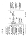
- the engine rotation speed detected by the engine rotation speed detector 1, the engine load detected(calculated) by the load detector 4, the crank angle detected by the crank angle sensor 3, the oil pressures of the lubricators 12a, 12b, 12c, ⁇ ⁇ ⁇ , 12n detected by the oil pressure sensors 21, the specific gravity of lube oil measured by the specific gravimeter 9 and viscosity of lube oil measured by the viscosity meter 10, are inputted to a calculation part 191 (see FIG.2 ) for calculating timing and period of opening of each electromagnetic valve.
- measured lift L of each of the electromagnetic valves 17a, 17b, 17c, 17d, 17e, ⁇ ⁇ ⁇ , 17n and measured air gap Ga are also inputted to the calculation part 191 for calculating timing and period of opening of electromagnetic valve.
- FIG. 2 showing the control block diagram, and FIG. 1 .
- Reference numeral 192 is a setting part of timing and period of opening of each electromagnetic valve, in which target or permissible values of timing and period of opening of each valve corresponding to said detected values are set.
- the controller 19 performs calculations and controls on the basis of each value detected and the target or permissible values set in the setting part 192 as follows:
- the calculation part 191 for calculating the timing and period of opening of electromagnetic valve compares the actual amount of lube oil supply, which is calculated as a function of the opening period of electromagnetic valve, or lube oil injection ratio with the minimum amount of lube oil or minimum lube oil injection ratio preset in the opening timing and period setting part 192, and the opening period of each of the electromagnetic valves 17a, 17b, 17c, ⁇ ⁇ ⁇ , 17n is controlled so that lube oil of an amount larger than the minimum amount is supplied or so that lube oil injection ratio is larger than the minimum lube oil injection ratio.
- the opening period of the concerned electromagnetic valve is lengthened to increase the amount of lube oil to be supplied to the cylinder, and when said actual amount is larger than said minimum value determined corresponding to engine operation conditions, the opening period of the concerned electromagnetic valve is shortened to decrease the amount of lube oil to be supplied to the cylinder, so that an amount of lube oil capable of properly lubricating the inner surface of the cylinder 11 can be supplied always in accordance with engine operating conditions.
- timing and period of opening setting part 192 are set lube oil feeding modes of feeding lube oil from the lubricator 12a, 12b, 12c, ⁇ ⁇ ⁇ , 12n once per a few number of cycles of engine rotation when the engine is operated under low load lower than a certain reference load and feeding lube oil from the lubricator 12a, 12b, 12c, ⁇ ⁇ ⁇ , 12n for every cycle when the engine is operated under high load higher than a certain reference load.
- the timing and period of opening calculating part 191 selects a lube oil feeding mode corresponding to the engine rotation speed and engine load inputted from the engine rotation speed detector 1 and load detector 4 respectively from the modes set in the timing and period of opening setting part 192, lube oil is supplied from the lubricators 12a, 12b, 12c, ⁇ ⁇ ⁇ , 12n once per a few number of cycles of engine rotation when the engine is operated under low load lower than a certain reference load, and lube oil is supplied from the lubricators 12a, 12b, 12c, ⁇ ⁇ ⁇ , 12n for every cycle when the engine is operated under high load higher than a certain reference load.
- lube oil is supplied in accordance with the detected engine load (or engine rotation speed) such that lube oil is supplied for every cycle when operating at a high load(or high rotation speed) with which lubricating condition on the inner surface of cylinder is severe and lube oil is supplied once for a few number of cycles when operating at a low load (or low rotation speed) with which the lubricating condition is not so severe, so that lubricating oil consumption is decreased particularly in low load operation.
- timing and period of opening setting part 192 is set relations between reference(target) values of engine load(or rotation speed) and lube oil injection ratio(injection amount of lube oil per hour/engine load or engine output) of the amount of the fuel supplied from the lubricators 12a, 12b, 12c, ⁇ ⁇ ⁇ , 12n.
- the timing and period of opening calculating part 191 calculates lube oil injection ratio on the basis of the actual amount of oil supplied to cylinder and the detected engine load, compares the calculated lube oil injection ratio with the reference(target) value of lube oil injection ratio corresponding to the engine load set in the timing and period of opening setting part 192, and the opening periods of each of the electromagnetic valves 17a, 17b, 17c, ⁇ ⁇ ⁇ , 17n are controlled according to the result of comparison so that the opening period thereof coincides with said reference (target) value.
- each of the electromagnetic valves 17a, 17b, 17c, ⁇ ⁇ ⁇ , 17n iscontrolled so that the lube oil injection ratio calculated on the basis of actual amount of lube oil supply and detected engine load coincide with reference value of lube oil injection ratio targeted, preferably a constant value, in all over the engine operation conditions, lube oil is accurately controlled to be supplied to the inner surface of the cylinder liner 11 by an amount with which proper lubrication is carried out and lube oil consumption can be reduced to a minimum in all over the operation conditions of the engine.
- timing and period of opening setting part 192 is set a relation between the lube oil feeding pressure to the cylinder liner 11 and the opening period of the electromagnetic valve, i.e. the amount of lube oil supply.
- the timing and period of opening calculating part 191 takes out from the timing and period of opening setting part 192 the opening period of each of the electromagnetic valves 17a, 17b, 17c, ⁇ ⁇ ⁇ , 17n corresponding to the detected lube oil feeding pressure in the common lube oil feeding section 15 sent from the pressure sensor 21.
- timing and period of opening setting part 192 is set a relation between the specific gravity of lube oil and the opening period of the electromagnetic valve, i.e. the amount of lube oil supply such that the opening period is shortened as the specific gravity of lube oil increases and the opening period is lengthened as the specific gravity of lube oil decreases.
- the timing and period of opening calculating part 191 takes out from the timing and period of opening setting part 192 the opening period of each of the electromagnetic valves 17a, 17b, 17c, ⁇ ⁇ ⁇ , 17n corresponding to the detected specific gravity of lube oil inputted from the specific gravimeter.
- timing and period of opening setting part 192 is set a relation between the viscosity of lube oil and the timing and period of opening of the electromagnetic valve, i.e. the amount of lube oil supply such that the timing is advanced and the period is lengthened as the viscosity of lube oil increases and the timing is retarded and the period is shortened as the viscosity of lube oil decreases.
- the timing and period of opening calculating part 191 takes out from the timing and period of opening setting part 192 the timing and period of each of the electromagnetic valves 17a, 17b, 17c, ⁇ ⁇ ⁇ , 17n corresponding to the detected viscosity of lube oil inputted from the viscosity meter.
- timing and period of opening setting part 192 is set a relation between the lift L of the electromagnetic valve as shown in FIG.7 and the opening period thereof so that the opening period is shortened as the lift L increases in order that the amount of lube oil supply is always constant.
- the timing and period of opening calculating part 191 takes out from the timing and period of opening setting part 192 the opening period of each of the electromagnetic valves 17a, 17b, 17c, ⁇ ⁇ ⁇ , 17n corresponding to the measured value of lift L.
- timing and period of opening setting part 192 is set a relation between the air gap Ga of the electromagnetic valve as shown in FIG.7 and the opening period thereof so that the opening period is shortened as the air gap Ga increases in order that the amount of lube oil supply is always constant.
- the timing and period of opening calculating part 191 takes out from the timing and period of opening setting part 192 the opening period of each of the electromagnetic valves 17a, 17b, 17c, ⁇ ⁇ ⁇ , 17n corresponding to the measured value of air gap Ga.
- timing and period of opening setting part 192 is set a relation between the sulfur concentration in fuel and the opening period of the electromagnetic valve so that the opening period is determined to allow a minimum amount of lube oil necessary to neutralize the sulfur to flow.
- the timing and period of opening calculating part 191 takes out from the timing and period of opening setting part 192 the opening period of each of the electromagnetic valves 17a, 17b, 17c, ⁇ ⁇ ⁇ , 17n corresponding to the sulfur concentration in fuel.
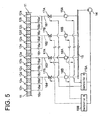
- FIG. 3 to FIG. 5 showing the second to fourth embodiments, a variety of connections between the electromagnetic valves 17 and the lubricators 12 are shown.
- a plurality of the lubricators 12 are attached to one cylinder as shown by 12a, 12b, 12c, 12d, 12e, ⁇ ⁇ ⁇ , 12n , and oil passages connecting to the lubricators 12 are composed to consist of main passages 161, 162, 163, and 164 and branch oil passages 16a, 16b, 16c, 16d, 16e, ⁇ ⁇ ⁇ , 16n (corresponding to the oil passages in the first embodiment) branching from the main passages 161, 162, 163, and 164 to be connected to each of the lubricators 12a, 12b, 12c, 12d, 12e, ⁇ ⁇ ⁇ , 12n.
- An electromagnetic valve 17 is provided to each of main oil passages, that is, a valve 17A and a valve 17B are provided to the main oil passages 161, and 162 respectively and another valve 17A and valve 17B are provided to the main oil passages 163 and 164 respectively.
- a valve 17A and a valve 17B are provided to the main oil passages 161, and 162 respectively
- another valve 17A and valve 17B are provided to the main oil passages 163 and 164 respectively.
- Reference numeral 18A is a lube oil flow limiter located upstream of the electromagnetic valve 17A
- 18B is a lube oil flow limiter located upstream of the electromagnetic valve 17B.
- the composition other than the points mentioned above is the same as that of the first embodiment shown in FIG.1 and the same component is indicated by the same reference numeral.
- detectors and sensors shown in FIG. 1 are omitted in FIG.3 .
- the branch oil passages 16a, 16b, 16c, 16d, 16e, ⁇ ⁇ ⁇ , 16n connected to the lubricators 12a, 12b, 12c, 12d, 12e, ⁇ ⁇ ⁇ , 12n arranged along the periphery of one cylinder liner 11 are connected alternately to the main oil passages 161, 162, 163, and 164.
- the electromagnetic valves 17A and 17B provided to the main oil passages 161 and 162 control respectively the lube oil flow to the alternately disposed lubricators, that is, for example, the valves 17A controls the lubricators 12a, 12c, and 12d, and valves 17B controls the lubricators 12b, 12d, and 12n. By this, controlling of lube oil supply is evened along the circumferential direction of the cylinder.
- composition other than the points mentioned above is the same as that of the first embodiment shown in FIG.1 or the second embodiment shown in FIG.3 and the same component is indicated by the same reference numeral.
- detectors and sensors shown in FIG. 1 are omitted in FIG.3 .
- a plurality of the lubricators 12 are attached to one cylinder as shown by 12a, 12b, 12c, 12d, 12e, ⁇ ⁇ ⁇ , 1 2 n
- oil passages connecting to the lubricators 12 are composed to consist of main passages 161, 162, 163, and 164 and branch oil passages 16a, 16b, 16c, 16d, 16e, ⁇ ⁇ ⁇ , 16n (corresponding to the oil passages in the first embodiment) branching from the main passages 161, 162, 163, and 164 to be connected to each of the lubricators 12a, 12b, 12c, 12d, 12e, ⁇ ⁇ ⁇ , 12n, as is in the case of the second embodiment.
- a plurality of controllers 19A and 19B instead of a single controller 19 in the second embodiment, and the electromagnetic valves 17A and 17B are controlled independently by the controller 19A, and 19B respectively.
- composition other than the points mentioned above is the same as that of the first embodiment shown in FIG. 1 or the second embodiment shown in FIG.3 and the same component is indicated by the same reference numeral.
- detectors and sensors shown in FIG. 1 are omitted in FIG.5 .
- a return pipe 23 and a pressure regulation valve 22 are provided to allow the lube oil in the common lube oil feeding section 15 to return to the lube oil pump 14 so that lube oil temperature in the common lube oil feeding section 15 is even along the widely extending section 15 by heating the lube oil in the common lube oil feeding section 15 by the lube oil in the return pipe 23.
- composition other than the points mentioned above is the same as that of the first embodiment shown in FIG.1 or the second embodiment shown in FIG.3 and the same component is indicated by the same reference numeral.
- detectors and sensors shown in FIG. 1 are omitted in FIG.6 .
- the opening area of each of the electromagnetic valves 17(17a, 17b, 17c, ⁇ ⁇ ⁇ , 17n) is larger than the sum of the passage area of the lubricators connected to the concerned electromagnetic valve (for example, In FIG.4 , the opening area of the valve 17A is larger than the sum of the passage area of the lubricator 12a, 12b, and 12c) .
- FIG.8 is an overall schematic representation of the sixth embodiment of the cylinder lubricating system of a diesel engine according to the present invention
- FIG. 9 is an enlarged detail of a part indicated by Z in FIG.8 .
- reference numeral 11 is a cylinder liner (cylinder)
- 51 is a piston which reciprocates along the inner surface 11a of the cylinder liner 11
- 52 are a few number of piston rings received in ring groove of the piston 52 (in the drawing, four rings are provided).
- Reference numeral 53 are spaces between the piston rings 52 formed between the inner surface of the cylinder liner 11 and the outer surface of the piston 51.
- Reference numeral 56 is a cylinder cover, 55 is an exhaust valve, and 58 is a combustion chamber.
- the composition mentioned above is the same as that of prior art.
- Reference numeral 12 are lubricators (lube oil injectors) for injecting lube oil to the inner surface 11a of the cylinder liner 11.
- Two lubricators 12 are recognized in the drawing along the axial direction of the cylinder liner 11, and although not shown in the drawing, a plurality of lubricators are arranged along the periphery of the cylinder liner 11.
- the lubricators 12 are conventional ones used in large diesel engines(detailed explanation is omitted) and they may be arranged in a single row or in three or more rows along the periphery of one cylinder.
- Reference numeral 14 is a lube oil pump
- 15 is a common lube oil feeding section where the lube oil pressure-fed by the lube oil pump 14 is accumulated.
- Reference numeral 156 are oil passages connecting the common lube oil feeding section 15 to the lubricators 12 of each cylinder, 70 are electromagnetic valves provided to each of the oil passages 156 for opening/closing the oil passages 156.
- Reference numeral 1 is an engine rotation speed detector for detecting the rotation speed of the engine
- 4 is a load detector for detecting engine load (fuel injection quantity, etc.)
- 3 is crank angle sensor for detecting crank angles of engine, i.e. rotation positions of the crankshaft of engine .
- Reference numeral 19 is a controller, to which are inputted the crank angle detected by the crank angle sensor3, the engine rotation speed detected by the engine rotation speed detector 1, and the engine load detected by the load detector 4.
- the controller 19 controls the timing and period of opening of each of the electromagnetic valves 70 on the basis of those detected values to adjust the timing and quantity of lube oil injection from each of the lubricators(injectors) 12.
- Each of the electromagnetic valves 70 is controlled independently by the controller 19 to adjust the timing and period of opening thereof.
- the lube oil pressure-fed by the lube oil pump 14 is accumulated in the common lube oil feeding section 15.
- the lube oil accumulated in the common lube oil feeding section 15 is supplied to the lubricators 12 through the oil passages 156 and injected to the inner surface of the cylinder liner 11 from each of the lubricators 12.
- the controller 19 controls the timing and period of opening of each of the electromagnetic valves 70 on the basis of the detected values of crank angle, engine rotation speed, and engine load by the first or second method described in the following.
- the controlling by the first method is done as follows:
- the firstly injected lube oil injected when the top piston ring is at a position upper than the lubricators 12 is carried upward by the upward travel of the piston 51 to upper portions of the inner surface of the cylinder liner 11 where lubrication condition is severe, and the lube oil injected by the succeeding second lube oil injection from the lubricators 12 and existing in the spaces 53 between piston rings is carried upward along the inner surfaces of the cylinder liner 11. Therefore, lube oil can spread along the inner surface 11a of the cylinder liner in the axial direction and particularly spreading of lube oil toward upper portions of the inner surface 11a is improved.
- the controlling by the first method is done as follows:
- a first lube oil injection is done from the lubricators 12 arranged in two rows when the bottom piston ring(lowermost piston ring of the four piston rings in the drawing) is at a position upper than the lubricators 12(at a position upper than the lower lubricators in the case the lubricators are arranged in two rows as this example), then a second lube oil injection is done in the process of downward travel of the piston 51.
- a first lube oil injection is done from the lubricators 12 arranged in two rows when the bottom piston ring(lowermost piston ring of the four piston rings in the drawing) is at a position upper than the lubricators 12(at a position upper than the lower lubricators in the case the lubricators are arranged in two rows as this example), then a second lube oil injection is done in the process of downward travel of the piston 51.
- it is intended to inject lube oil at least to the lowermost space between piston rings, and lube oil is injected to other
- the firstly injected lube oil injected when the top piston ring is at a position upper than the lubricators 12 is carried downward by the downward travel of the piston 51 to lower portions of the inner surface of the cylinder liner 11 , and the lube oil injected by the succeeding second lube oil injection from the lubricators 12 and existing in the spaces 53 between piston rings is carried downward along the inner surfaces of the cylinder liner 11. Therefore, lube oil can spread along the inner surface 11a of the cylinder liner in the axial direction and particularly spreading of lube oil toward lower portions of the inner surface 11a is improved.
- the lubricators 12 arranged along the periphery of the cylinder liner 11(arranged in two rows in this example) may be attached to the cylinder such that the injection hole of each of the lubricators is directed to directions circumferential to the inner surface 11a of cylinder liner so that lube oil spreads widely in the circumferential direction of the inner surface 11a of cylinder.
- the injection hole of lubricators belonging at least to a row may be attached to the cylinder liner 11 such that the injection hole of each of the lubricators is directed to directions circumferential to the inner surface 11a of cylinder liner is directed.
- lube oil can be spread widely in the circumferential direction of the inner surface 11a of cylinder.
- lube oil is injected from a plurality of lubricators arranged in a plurality of row in the axial direction of cylinder liner 11 and lube oil injected from lubricators belonging to at leas a row is directed to the circumferential direction of the inner surface of cylinder, so that the spreading of lube oil in the axial direction is improved and lube oil spreads widely also in the circumferential direction on the inner surface 11a of cylinder liner.
- lube oil is injected from the lubricators 12 to the spaces 53 between piston rings at least once per one reciprocation of the piston 51, and the lube oil pooled in the spaces 53 between piston rings is transferred in the axial direction of the inner surface 11a of cylinder liner, so that an oil film of even thickness is formed on a wide range of the inner surface 11a of cylinder, particularly over a wide range along the axial direction thereof not only near portions where lube oil is injected from the lubricators.
- the cylinder lubricating system of the present invention it becomes possible to supply lube oil of required amount at required timing to each lubricator, that is, to each portion of the inner surface of cylinder independently, and normal supply of lube oil is possible even when malfunction occurs in some of the lubricators including magnetic valves to open / close the oil passages to supply lube oil to the lubricators. Further, the timing and amount of lube oil supply can be adjusted even in engine operation in accordance with varying factors such as properties of lube oil, lube oil pressure, etc. In addition, lube oil consumption can be reduced.
- lube oil of required amount at required timing it becomes possible to supply lube oil of required amount at required timing to each lubricator, that is, to each portion of the inner surface of cylinder independently, and supply amount of lube oil or lube oil injection ratio can be controlled so that a minimum amount of lube oil required to maintain good lubricating condition in the inner surface of cylinder to positively evade the occurrence of wear or sticking of piston or piston rings is supplied on the inner surface of cylinder. Therefore, lube oil consumption can be reduced compared with prior art of cylinder lubricating system in which the timing and amount of lube oil supply to a plurality of lubricators are adjusted uniformly not independently.
- the timing and supply amount or injection ratio of lube oil can be adjusted easily even in engine operation.
- the lube oil supplied and pooled in the spaces between piston rings is carried in the axial direction on the inner surface of cylinder and an oil film of even thickness is formed on a wide range of the inner surface 11a of cylinder, particularly over a wide range along the axial direction thereof not only near portions where lube oil is injected from the lubricators.
Landscapes
- Engineering & Computer Science (AREA)
- Mechanical Engineering (AREA)
- General Engineering & Computer Science (AREA)
- Chemical & Material Sciences (AREA)
- Combustion & Propulsion (AREA)
- Lubrication Of Internal Combustion Engines (AREA)
Claims (22)
- Moteur à combustion interne muni d'un système de lubrification dans lequel de l'huile lubrifiante alimentée sous pression par une pompe à huile lubrifiante (14) est logée dans une section d'alimentation en huile lubrifiante commune (15), l'huile lubrifiante contenue dans ladite section d'alimentation en huile lubrifiante commune est amenée à une pluralité de dispositifs de lubrification (12a, b, c, ..., n) à travers des passages d'huile lubrifiante (16a, b, c, ..., n) reliant ladite section d'alimentation en huile lubrifiante commune auxdits dispositifs de lubrification et est injectée vers les surfaces intérieures des cylindres (11) du moteur par lesdits dispositifs de lubrification, dans lequel sont disposées une pluralité de vannes électromagnétiques (17a, b, c, ..., n) pour ouvrir ou fermer chacun desdits passages d'huile lubrifiante indépendamment, et une unité de commande (19) pour commander la synchronisation et la période d'ouverture de chacune desdites vannes électromagnétiques indépendamment, et dans lequel ladite unité de commande calcule le taux d'injection d'huile lubrifiante, c'est-à-dire la quantité d'injection d'huile lubrifiante par heure / charge de moteur ou sortie de moteur, sur la base de la quantité d'alimentation en huile lubrifiante calculée comme une fonction de l'ouverture des vannes électromagnétiques et de la charge de moteur calculée à partir de la vitesse détectée de rotation de moteur et de la quantité d'entrée de carburant, et commande la période d'ouverture desdites vannes électromagnétiques de sorte que ledit taux d'injection d'huile lubrifiante calculé coïncide avec un taux d'injection d'huile lubrifiante déterminé à l'avance.
- Moteur à combustion interne muni d'un système de lubrification selon la revendication 1, dans lequel ladite unité de commande permet de commander lesdites vannes électromagnétiques de sorte que lorsqu'au moins une parmi deux ou plusieurs desdites vannes électromagnétiques qui sont associées par cylindre subit une défaillance, la période d'ouverture d'une autre vanne ou d'autres vannes est allongée.
- Moteur à combustion interne muni d'un système de lubrification selon les revendications 1 ou 2, dans lequel ladite unité de commande permet de commander la période d'ouverture desdites vannes électromagnétiques de sorte que la quantité d'alimentation en huile qui est déterminée comme une fonction de la période d'ouverture des vannes électromagnétiques, ou du taux d'injection d'huile lubrifiante calculé sur la base de ladite quantité d'alimentation en huile lubrifiante et de la charge de moteur, est plus grande que la quantité minimale prédéterminée d'alimentation en huile lubrifiante ou que le taux minimal d'injection d'huile lubrifiante.
- Moteur à combustion interne muni d'un système de lubrification selon les revendications 1, 2 ou 3, dans lequel un détecteur de vitesse de rotation de moteur (1) pour détecter la vitesse de rotation du moteur et un capteur d'entrée de carburant (2) pour détecter la quantité d'entrée de carburant sont prévus, ladite unité de commande calcule la charge de moteur sur la base de la vitesse de rotation de moteur et la quantité d'entrée de carburant détectée et commande l'ouverture / fermeture desdites vannes électromagnétiques de sorte que de l'huile lubrifiante est injectée à partir desdits dispositifs de lubrification à chaque cycle lorsque le moteur est mis en oeuvre à une charge élevée supérieure à une certaine charge, et une fois par un petit nombre de cycles lorsque le moteur est mis en oeuvre à une faible charge inférieure à ladite certaine charge.
- Moteur à combustion interne muni d'un système de lubrification selon l'une quelconque des revendications 1 à 4, dans lequel un détecteur de poids volumique (9) est prévu dans ladite section d'alimentation en huile lubrifiante commune, et ladite unité de commande permet de commander lesdites vannes électromagnétiques de sorte que leur période d'ouverture coïncide avec une valeur prédéterminée en correspondance avec la valeur de poids volumique d'huile lubrifiante entrée à l'avance dans l'unité de commande à partir du détecteur de poids volumique ou avec la valeur de poids volumique réel détectée par ledit détecteur de poids volumique.
- Moteur à combustion interne muni d'un système de lubrification selon la revendication 5, dans lequel ladite unité de commande permet de commander lesdites vannes électromagnétiques de sorte que leur synchronisation et leur période d'ouverture coïncident avec des valeurs prédéterminées en correspondance avec la valeur de viscosité de l'huile lubrifiante entrée à l'avance dans l'unité de commande à partir d'un dispositif de mesure de viscosité (10) associé à la section d'alimentation en huile lubrifiante commune ou avec la valeur de viscosité réelle détectée par ledit détecteur de poids volumique.
- Moteur à combustion interne muni d'un système de lubrification selon l'une quelconque des revendications 1 à 6, dans lequel un détecteur de pression (21) ou un détecteur de température est prévu dans ladite section d'alimentation en huile lubrifiante commune, et ladite unité de commande permet de commander lesdites vannes électromagnétiques de sorte que leur période d'ouverture coïncide avec des périodes prédéterminées en correspondance avec la pression ou la température d'huile lubrifiante dans la section d'alimentation en huile lubrifiante commune détectée par et entrée en provenance dudit détecteur de pression ou dudit détecteur de température.
- Moteur à combustion interne muni d'un système de lubrification selon l'une quelconque des revendications 1 à 7, dans lequel ladite unité de commande permet de commander lesdites vannes électromagnétiques de sorte que leur période d'ouverture coïncide avec des périodes prédéterminées en correspondance avec leur soulèvement (L) qui est prédéterminé ou mesuré.
- Moteur à combustion interne muni d'un système de lubrification selon l'une quelconque des revendications 1 à 8, dans lequel ladite unité de commande permet de commander lesdites vannes électromagnétiques en correspondance avec la valeur prédéterminée ou mesurée d'un entrefer (Ga) de ladite vanne électromagnétique.
- Moteur à combustion interne muni d'un système de lubrification selon l'une quelconque des revendications 1 à 9, dans lequel une pluralité de dispositifs de lubrification sont prévus par cylindre, chacun desdits passages d'huile est relié à chacun desdits dispositifs de lubrification, et chacune desdites vannes électromagnétiques est disposée dans chacun desdits passages d'huile.
- Moteur à combustion interne muni d'un système de lubrification selon la revendication 10, dans lequel une pluralité de dispositifs de lubrification sont prévus par cylindre, les passages d'huile lubrifiante consistent en un passage principal (161 à 164) et en passages ramifiés (16a, b, c, ..., n) se ramifiant à partir dudit passage principal et respectivement relié à chacun desdits dispositifs de lubrification, ladite vanne électromagnétique est disposée dans le passage d'huile principal, et une vanne électromagnétique unique (17) regit l'alimentation en huile lubrifiante vers une pluralité de dispositifs de lubrification.
- Moteur à combustion interne muni d'un système de lubrification selon la revendication 11, dans lequel les passages ramifiés se ramifiant à partir de chacun des passages principaux sont reliés aux dispositifs de lubrification situés en alternance le long de la périphérie du cylindre, de sorte que même si une des vannes électromagnétiques subit une défaillance, de l'huile lubrifiante peut être fournie aux dispositifs de lubrification disposés tout autour de la périphérie du cylindre à l'exception des dispositifs de lubrification reliés aux vannes électromagnétiques défaillantes.
- Moteur à combustion interne muni d'un système de lubrification selon l'une quelconque des revendications 1 à 12, dans lequel une pluralité de dispositifs de lubrification sont prévus par cylindre et une pluralité d'unités de commande (19A, B) sont prévues pour commander une ou une pluralité desdites vannes électromagnétiques.
- Moteur à combustion interne muni d'un système de lubrification selon l'une quelconque des revendications 1 à 13, dans lequel une vanne de régulation de pression (22) est disposée sur une partie d'extrémité de la section d'alimentation en huile lubrifiante commune, et la pompe à huile lubrifiante décharge plus d'huile lubrifiante que la quantité injectée dans les cylindres du moteur permettant à l'huile lubrifiante dans la section d'alimentation en huile lubrifiante commune de circuler en conservant la température de l'huile lubrifiante dans la section d'alimentation en huile lubrifiante commune à une température uniforme.
- Moteur à combustion interne muni d'un système de lubrification selon l'une quelconque des revendications 1 à 14, dans lequel un tuyau de retour (23) est disposé le long de la section d'alimentation en huile lubrifiante commune, et un échange de chaleur est possible entre l'huile lubrifiante dans la section d'alimentation en huile lubrifiante commune et celle dans le tuyau de retour.
- Moteur à combustion interne muni d'un système de lubrification selon l'une quelconque des revendications 1 à 15, dans lequel la surface d'ouverture de chacune des vannes électromagnétiques est plus grande que la somme de la surface de passage des dispositifs de lubrification reliés à la vanne électromagnétique concernée.
- Moteur à combustion interne muni d'un système de lubrification de cylindre selon l'une quelconque des revendications 1 à 16, dans lequel on prévoit un capteur de position de vilebrequin (3) pour détecter une position de vilebrequin de moteur, un détecteur de vitesse de rotation (1) pour détecter la vitesse de rotation de moteur, un détecteur de charge (4) pour détecter la charge de moteur, et une unité de commande (19) pour commander les vannes électromagnétiques de sorte que de l'huile lubrifiante est injectée à partir des dispositifs de lubrification vers des espaces formés entre des segments de piston (52) d'un piston (51) allant et venant dans le cylindre (11) au moins une fois par aller-retour du piston sur la base des valeurs détectées par le capteur de position de vilebrequin, le détecteur de vitesse de rotation et le détecteur de charge.
- Procédé d'alimentation en huile lubrifiante vers des cylindres dans un système dans lequel l'huile lubrifiante alimentée sous pression par une pompe à huile lubrifiante est fournie à des dispositifs de lubrification associés à un cylindre par l'intermédiaire de vannes électromagnétiques pour ajuster la synchronisation et la quantité d'alimentation en huile lubrifiante et à des passages d'huile pour amener l'huile lubrifiante vers la surface intérieure d'un cylindre dans lequel un piston, ayant une pluralité de segments de piston, va et vient, dans lequel de l'huile lubrifiante est injectée à partir des dispositifs de lubrification vers des espaces formés entre les segments de piston au moins une fois par aller-retour du piston, et dans lequel un taux d'injection d'huile lubrifiante est calculé, c'est-à-dire la quantité d'injection d'huile lubrifiante par heure / charge de moteur ou sortie de moteur, sur la base de la quantité d'alimentation en huile lubrifiante calculée comme une fonction de l'ouverture des vannes électromagnétiques et de la charge de moteur calculée à partir de la vitesse de rotation détectée de moteur et de la quantité d'entrée de carburant, et la période d'ouverture desdites vannes électromagnétiques est commandée de sorte que ledit taux d'injection d'huile lubrifiante calculé coïncide avec un taux d'injection d'huile lubrifiante déterminé à l'avance.
- Procédé d'alimentation en huile lubrifiante vers des cylindres selon la revendication 18, dans lequel une première injection d'huile lubrifiante est effectuée lorsque le piston se déplace vers le haut et est à une position plus basse que le(s) dispositif (s) de lubrification et ensuite une seconde injection d'huile lubrifiante est effectuée vers les espaces entre les segments de piston dans le processus de déplacement ascendant du piston.
- Procédé d'alimentation en huile lubrifiante vers des cylindres selon la revendication 18, dans lequel une première injection d'huile lubrifiante est effectuée lorsque le piston se déplace vers le bas et est à une position plus élevée que le(s) dispositif(s) de lubrification et ensuite une seconde injection d'huile lubrifiante est effectuée vers les espaces entre les segments de piston dans le processus de déplacement descendant du piston.
- Procédé d'alimentation en huile lubrifiante vers des cylindres selon la revendication 18, 19 ou 20, dans lequel les dispositifs de lubrification sont associés au cylindre de sorte que le trou d'injection de chacun des dispositifs de lubrification est orienté vers des directions circonférentielles à la surface intérieure du cylindre de sorte que l'on permet à l'huile lubrifiante d'être injectée depuis les dispositifs de lubrification dans des directions circonférentielles à la surface intérieure du cylindre.
- Procédé d'alimentation en huile lubrifiante vers des cylindres selon la revendication 18, 19 ou 20, dans lequel les dispositifs de lubrification sont agencés dans une pluralité de rangées le long de la périphérie d'un cylindre, et les dispositifs de lubrification appartenant à au moins une rangée sont associés au cylindre de sorte que le trou d'injection de chacun des dispositifs de lubrification est orienté vers des directions circonférentielles à la surface intérieure du cylindre de sorte que l'on permet à l'huile lubrifiante d'être injectée depuis les dispositifs de lubrification dans des directions circonférentielles à la surface intérieure du cylindre.
Applications Claiming Priority (4)
| Application Number | Priority Date | Filing Date | Title |
|---|---|---|---|
| JP2004108158 | 2004-03-31 | ||
| JP2004108158A JP3897770B2 (ja) | 2004-03-31 | 2004-03-31 | シリンダ注油装置を備えた内燃機関 |
| JP2005054678 | 2005-02-28 | ||
| JP2005054678A JP4402609B2 (ja) | 2005-02-28 | 2005-02-28 | シリンダ注油装置 |
Publications (3)
| Publication Number | Publication Date |
|---|---|
| EP1582706A2 EP1582706A2 (fr) | 2005-10-05 |
| EP1582706A3 EP1582706A3 (fr) | 2005-11-09 |
| EP1582706B1 true EP1582706B1 (fr) | 2008-07-16 |
Family
ID=34889462
Family Applications (1)
| Application Number | Title | Priority Date | Filing Date |
|---|---|---|---|
| EP05006988A Expired - Lifetime EP1582706B1 (fr) | 2004-03-31 | 2005-03-31 | Moteur à combustion interne ayant un dispositif de lubrification du cylindre |
Country Status (5)
| Country | Link |
|---|---|
| EP (1) | EP1582706B1 (fr) |
| KR (2) | KR100750542B1 (fr) |
| CN (2) | CN100549369C (fr) |
| DE (1) | DE602005008126D1 (fr) |
| DK (1) | DK1582706T3 (fr) |
Cited By (2)
| Publication number | Priority date | Publication date | Assignee | Title |
|---|---|---|---|---|
| EP4139564A4 (fr) * | 2020-04-22 | 2024-05-22 | Hans Jensen Lubricators A/S | Procédé de lubrification de gros moteurs diesel marins lents |
| US12269729B2 (en) | 2023-01-27 | 2025-04-08 | Vgp Ipco Llc | Reusable or refillable container for dispensing motor oil |
Families Citing this family (24)
| Publication number | Priority date | Publication date | Assignee | Title |
|---|---|---|---|---|
| DK176934B1 (da) * | 2007-05-18 | 2010-05-31 | Hans Jensen Lubricators As | Smøreapparat samt fremgangsmåde til dosering af cylindersmøreolie |
| DK2177720T3 (da) * | 2008-10-16 | 2014-06-30 | Wärtsilä Schweiz AG | Stor dieselmotor |
| DK177746B1 (da) | 2009-06-23 | 2014-05-26 | Hans Jensen Lubricators As | Fremgangsmåde til cylindersmøring af store dieselmotorer såsom skibsmotorer |
| EP2395208A1 (fr) * | 2010-06-11 | 2011-12-14 | Wärtsilä Schweiz AG | Grand moteur doté d'un dispositif de lubrification de cylindre et procédé de lubrification d'un cylindre d'un grand moteur |
| WO2012029553A1 (fr) * | 2010-09-01 | 2012-03-08 | 株式会社Ihi | Générateur d'électricité par récupération de chaleur |
| EP2484875B1 (fr) * | 2011-02-04 | 2013-11-27 | Wärtsilä Schweiz AG | Dispositif de lubrification de cylindre |
| DK177258B1 (da) * | 2011-03-18 | 2012-08-27 | Hans Jensen Lubricators As | Doseringssystem for cylindersmøreolie til store cylindre samt fremgangsmåde til dosering af cylindersmøreolie til store cylindre |
| CN102322309A (zh) * | 2011-09-27 | 2012-01-18 | 上海北星实业有限公司 | 一种引擎上的曲轴润滑方法及装置 |
| JP5933217B2 (ja) | 2011-10-12 | 2016-06-08 | 株式会社Ihi | 2サイクルエンジン及び2サイクルエンジンの注油方法 |
| US9004039B2 (en) * | 2012-10-23 | 2015-04-14 | GM Global Technology Operations LLC | Cylinder lubrication system |
| CN103485856B (zh) * | 2013-09-30 | 2015-10-28 | 南安市文发电子科技有限公司 | 活塞同步负压控制润滑孔的控制装置 |
| CN105673244A (zh) * | 2013-09-30 | 2016-06-15 | 庄景阳 | 借助离合刹车信号控制汽缸润滑的方法 |
| CN103470392B (zh) * | 2013-09-30 | 2015-07-01 | 庄景阳 | 点火角度控制汽缸的润滑装置 |
| CN106164426B (zh) * | 2014-03-25 | 2018-10-09 | 汉斯延森注油器公司 | 为汽缸配给润滑油的方法及系统 |
| EP3130771A1 (fr) * | 2015-08-13 | 2017-02-15 | Winterthur Gas & Diesel AG | Dispositif de lubrification pour revetement de cylindre, procede de lubrification et revetement de cylindre |
| DK179182B1 (en) * | 2016-08-05 | 2018-01-15 | Hans Jensen Lubricators As | Safety system for lubrication of the cylinder of a large slow-running internal combustion engine and a large slow-running two-stroke internal combustion engine |
| JP6685864B2 (ja) * | 2016-08-29 | 2020-04-22 | 三菱重工業株式会社 | シリンダ注油装置及びクロスヘッド式内燃機関 |
| CN106567960B (zh) * | 2016-10-17 | 2019-07-05 | 潍柴动力股份有限公司 | 一种电磁阀的控制方法和系统 |
| EP3404224A1 (fr) * | 2017-05-19 | 2018-11-21 | Winterthur Gas & Diesel AG | Dispositif de lubrification pour un gros moteur diesel, procédé de lubrification de cylindre d'un gros moteur diesel et gros moteur diesel |
| JP7309110B2 (ja) * | 2017-12-07 | 2023-07-18 | 株式会社三井E&S Du | エンジンシステム |
| JP6973187B2 (ja) * | 2018-03-06 | 2021-11-24 | トヨタ自動車株式会社 | 内燃機関の燃料噴射時期制御装置 |
| CN108343830B (zh) * | 2018-03-31 | 2024-05-28 | 上汽通用五菱汽车股份有限公司 | 发动机缸孔润滑装置 |
| CN111156093B (zh) * | 2019-12-31 | 2023-01-06 | 潍柴动力股份有限公司 | 柴油-醇类双燃料发动机的控制方法和装置 |
| JP7745365B2 (ja) * | 2021-05-20 | 2025-09-29 | 株式会社ジャパンエンジンコーポレーション | シリンダ注油システム |
Family Cites Families (13)
| Publication number | Priority date | Publication date | Assignee | Title |
|---|---|---|---|---|
| GR75371B (fr) * | 1980-10-04 | 1984-07-13 | British Petroleum Co | |
| JPS6045710A (ja) | 1983-08-23 | 1985-03-12 | Nachi Fujikoshi Corp | ディ−ゼルエンジン注油装置 |
| DK171974B1 (da) * | 1988-11-01 | 1997-09-01 | Mitsubishi Heavy Ind Ltd | Smøreaggregat til en cylinder i en forbrændingsmotor |
| JPH02135612U (fr) * | 1989-04-14 | 1990-11-13 | ||
| JPH04318253A (ja) * | 1991-04-18 | 1992-11-09 | Mitsubishi Heavy Ind Ltd | 多気筒エンジン |
| DK173288B1 (da) * | 1996-10-11 | 2000-06-13 | Man B & W Diesel As | Cylindersmøreenhed til en flercylindret forbrændingsmotor, og fremgangsmåde til styring af leveringsmængden fra en cylinder |
| CA2350105A1 (fr) * | 1998-11-05 | 2000-05-18 | Hans Jensen Lubricators A/S | Systeme de lubrification pour moteurs diesel de grande taille |
| DK173533B1 (da) | 1999-01-18 | 2001-02-05 | Man B & W Diesel As | Fremgangsmåde til smøring af en cylinder i en forbrændingsmotor samt cylindersmøresystem og tilslutningselement |
| DE19959300A1 (de) | 1999-12-09 | 2001-06-21 | Man B & W Diesel As Kopenhagen | Motor |
| DE19959309A1 (de) | 1999-12-09 | 2001-06-21 | Man B & W Diesel As Kopenhagen | Motor |
| JP4685329B2 (ja) * | 2000-10-24 | 2011-05-18 | ハンス イエンセン ルブリカトーズ アクティーゼルスカブ | 分配装置 |
| JP3806398B2 (ja) * | 2002-11-28 | 2006-08-09 | 三菱重工業株式会社 | シリンダ注油装置 |
| JP3897770B2 (ja) | 2004-03-31 | 2007-03-28 | 三菱重工業株式会社 | シリンダ注油装置を備えた内燃機関 |
-
2005
- 2005-03-31 KR KR1020050027386A patent/KR100750542B1/ko not_active Expired - Fee Related
- 2005-03-31 DK DK05006988T patent/DK1582706T3/da active
- 2005-03-31 DE DE602005008126T patent/DE602005008126D1/de not_active Expired - Lifetime
- 2005-03-31 CN CNB2007101063953A patent/CN100549369C/zh not_active Expired - Fee Related
- 2005-03-31 EP EP05006988A patent/EP1582706B1/fr not_active Expired - Lifetime
- 2005-03-31 CN CN2005100716192A patent/CN1676888B/zh not_active Expired - Fee Related
-
2007
- 2007-03-23 KR KR1020070028621A patent/KR20070041697A/ko not_active Ceased
Cited By (2)
| Publication number | Priority date | Publication date | Assignee | Title |
|---|---|---|---|---|
| EP4139564A4 (fr) * | 2020-04-22 | 2024-05-22 | Hans Jensen Lubricators A/S | Procédé de lubrification de gros moteurs diesel marins lents |
| US12269729B2 (en) | 2023-01-27 | 2025-04-08 | Vgp Ipco Llc | Reusable or refillable container for dispensing motor oil |
Also Published As
| Publication number | Publication date |
|---|---|
| DK1582706T3 (da) | 2008-09-29 |
| CN1676888B (zh) | 2010-09-01 |
| EP1582706A3 (fr) | 2005-11-09 |
| CN100549369C (zh) | 2009-10-14 |
| EP1582706A2 (fr) | 2005-10-05 |
| CN101054913A (zh) | 2007-10-17 |
| KR20060045405A (ko) | 2006-05-17 |
| DE602005008126D1 (de) | 2008-08-28 |
| CN1676888A (zh) | 2005-10-05 |
| KR100750542B1 (ko) | 2007-08-20 |
| KR20070041697A (ko) | 2007-04-19 |
Similar Documents
| Publication | Publication Date | Title |
|---|---|---|
| EP1582706B1 (fr) | Moteur à combustion interne ayant un dispositif de lubrification du cylindre | |
| JP3806398B2 (ja) | シリンダ注油装置 | |
| EP1427935B1 (fr) | Procede de commande hybride d'une pompe a carburant au moyen de la recirculation intermittente a des regimes moteur lent et rapide | |
| EP0631046B1 (fr) | Système de commande du début et la quantité d'injection de combustible | |
| RU2674854C2 (ru) | Способ (варианты) и система подачи масла в двигатель внутреннего сгорания | |
| US7726948B2 (en) | Hydraulic pump with variable flow and variable pressure and electric control | |
| US5042445A (en) | Electronic controlled fuel supply system for high pressure injector | |
| US5896841A (en) | Electronically controlled hydraulic actuation type fuel injection device utilizing oil viscosity detection device and method | |
| US20170350304A1 (en) | Piston cooling device | |
| US20040112340A1 (en) | Common rail fuel injection control device | |
| US5893347A (en) | Method for delivering a small quantity of fuel with a hydraulically-actuated injector during split injection | |
| US4971016A (en) | Electronic controlled fuel supply system for high pressure injector | |
| JP2011256867A (ja) | シリンダ潤滑装置を有する大型エンジン及び大型エンジンシリンダ潤滑方法 | |
| EP1586751A2 (fr) | Moteur à combustion avec un dispositif de lubrification des cylindres | |
| EP1674716B1 (fr) | Système d'injection de carburant comprenant une pompe à carburant à haute pression à débit variable | |
| US5076236A (en) | Fuel cutoff for better transient control | |
| US6415762B1 (en) | Accurate deliver of total fuel when two injection events are closely coupled | |
| US5560825A (en) | Edge filter for a high pressure hydraulic system | |
| JP3897770B2 (ja) | シリンダ注油装置を備えた内燃機関 | |
| US11828256B2 (en) | Injector apparatus | |
| US11828257B2 (en) | Injector apparatus | |
| CN115387892A (zh) | 发动机的活塞冷却装置及其控制方法 | |
| KR20010062690A (ko) | 복합 초기 주입 및 피크 주입 압력 조절기를 구비한 연료주입 조립체 | |
| KR101211782B1 (ko) | 대형디젤엔진에 실린더면의 윤활방법과 윤활장치 | |
| US20170306878A1 (en) | Engine with direct injection and port fuel injection adjustment based upon engine oil parameters |
Legal Events
| Date | Code | Title | Description |
|---|---|---|---|
| PUAI | Public reference made under article 153(3) epc to a published international application that has entered the european phase |
Free format text: ORIGINAL CODE: 0009012 |
|
| PUAL | Search report despatched |
Free format text: ORIGINAL CODE: 0009013 |
|
| 17P | Request for examination filed |
Effective date: 20050331 |
|
| AK | Designated contracting states |
Kind code of ref document: A2 Designated state(s): AT BE BG CH CY CZ DE DK EE ES FI FR GB GR HU IE IS IT LI LT LU MC NL PL PT RO SE SI SK TR |
|
| AX | Request for extension of the european patent |
Extension state: AL BA HR LV MK YU |
|
| AK | Designated contracting states |
Kind code of ref document: A3 Designated state(s): AT BE BG CH CY CZ DE DK EE ES FI FR GB GR HU IE IS IT LI LT LU MC NL PL PT RO SE SI SK TR |
|
| AX | Request for extension of the european patent |
Extension state: AL BA HR LV MK YU |
|
| RIC1 | Information provided on ipc code assigned before grant |
Ipc: 7F 01M 1/14 B Ipc: 7F 01M 1/08 B Ipc: 7F 01M 9/00 B Ipc: 7F 01M 1/02 A |
|
| AKX | Designation fees paid |
Designated state(s): CH DE DK LI |
|
| 17Q | First examination report despatched |
Effective date: 20060301 |
|
| 17Q | First examination report despatched |
Effective date: 20060301 |
|
| GRAP | Despatch of communication of intention to grant a patent |
Free format text: ORIGINAL CODE: EPIDOSNIGR1 |
|
| GRAS | Grant fee paid |
Free format text: ORIGINAL CODE: EPIDOSNIGR3 |
|
| GRAA | (expected) grant |
Free format text: ORIGINAL CODE: 0009210 |
|
| AK | Designated contracting states |
Kind code of ref document: B1 Designated state(s): CH DE DK LI |
|
| RIN1 | Information on inventor provided before grant (corrected) |
Inventor name: SONODA, TAKASHI Inventor name: IZUMI, MOTOKI Inventor name: YAMAMOTO, TETSUYA Inventor name: YOSHIHARA, SADAO Inventor name: MURATA, SATORU |
|
| REG | Reference to a national code |
Ref country code: CH Ref legal event code: NV Representative=s name: E. BLUM & CO. AG PATENT- UND MARKENANWAELTE VSP Ref country code: CH Ref legal event code: EP |
|
| REF | Corresponds to: |
Ref document number: 602005008126 Country of ref document: DE Date of ref document: 20080828 Kind code of ref document: P |
|
| REG | Reference to a national code |
Ref country code: DK Ref legal event code: T3 |
|
| PLBE | No opposition filed within time limit |
Free format text: ORIGINAL CODE: 0009261 |
|
| STAA | Information on the status of an ep patent application or granted ep patent |
Free format text: STATUS: NO OPPOSITION FILED WITHIN TIME LIMIT |
|
| 26N | No opposition filed |
Effective date: 20090417 |
|
| PGFP | Annual fee paid to national office [announced via postgrant information from national office to epo] |
Ref country code: CH Payment date: 20120313 Year of fee payment: 8 |
|
| PGFP | Annual fee paid to national office [announced via postgrant information from national office to epo] |
Ref country code: DK Payment date: 20120312 Year of fee payment: 8 |
|
| PGFP | Annual fee paid to national office [announced via postgrant information from national office to epo] |
Ref country code: DE Payment date: 20120411 Year of fee payment: 8 |
|
| REG | Reference to a national code |
Ref country code: DK Ref legal event code: EBP Effective date: 20130331 Ref country code: DK Ref legal event code: EBP |
|
| REG | Reference to a national code |
Ref country code: CH Ref legal event code: PL |
|
| REG | Reference to a national code |
Ref country code: DE Ref legal event code: R119 Ref document number: 602005008126 Country of ref document: DE Effective date: 20131001 |
|
| PG25 | Lapsed in a contracting state [announced via postgrant information from national office to epo] |
Ref country code: CH Free format text: LAPSE BECAUSE OF NON-PAYMENT OF DUE FEES Effective date: 20130331 Ref country code: LI Free format text: LAPSE BECAUSE OF NON-PAYMENT OF DUE FEES Effective date: 20130331 Ref country code: DE Free format text: LAPSE BECAUSE OF NON-PAYMENT OF DUE FEES Effective date: 20131001 |
|
| PG25 | Lapsed in a contracting state [announced via postgrant information from national office to epo] |
Ref country code: DK Free format text: LAPSE BECAUSE OF NON-PAYMENT OF DUE FEES Effective date: 20130331 |