EP1582743A2 - Regelventil für einen Verdichter variabler Verdrängung - Google Patents
Regelventil für einen Verdichter variabler Verdrängung Download PDFInfo
- Publication number
- EP1582743A2 EP1582743A2 EP05005894A EP05005894A EP1582743A2 EP 1582743 A2 EP1582743 A2 EP 1582743A2 EP 05005894 A EP05005894 A EP 05005894A EP 05005894 A EP05005894 A EP 05005894A EP 1582743 A2 EP1582743 A2 EP 1582743A2
- Authority
- EP
- European Patent Office
- Prior art keywords
- control valve
- diaphragm
- bottomed sleeve
- core
- plunger
- Prior art date
- Legal status (The legal status is an assumption and is not a legal conclusion. Google has not performed a legal analysis and makes no representation as to the accuracy of the status listed.)
- Withdrawn
Links
Images



Classifications
-
- F—MECHANICAL ENGINEERING; LIGHTING; HEATING; WEAPONS; BLASTING
- F04—POSITIVE - DISPLACEMENT MACHINES FOR LIQUIDS; PUMPS FOR LIQUIDS OR ELASTIC FLUIDS
- F04B—POSITIVE-DISPLACEMENT MACHINES FOR LIQUIDS; PUMPS
- F04B27/00—Multi-cylinder pumps specially adapted for elastic fluids and characterised by number or arrangement of cylinders
- F04B27/08—Multi-cylinder pumps specially adapted for elastic fluids and characterised by number or arrangement of cylinders having cylinders coaxial with, or parallel or inclined to, main shaft axis
- F04B27/14—Control
- F04B27/16—Control of pumps with stationary cylinders
- F04B27/18—Control of pumps with stationary cylinders by varying the relative positions of a swash plate and a cylinder block
- F04B27/1804—Controlled by crankcase pressure
-
- F—MECHANICAL ENGINEERING; LIGHTING; HEATING; WEAPONS; BLASTING
- F04—POSITIVE - DISPLACEMENT MACHINES FOR LIQUIDS; PUMPS FOR LIQUIDS OR ELASTIC FLUIDS
- F04B—POSITIVE-DISPLACEMENT MACHINES FOR LIQUIDS; PUMPS
- F04B27/00—Multi-cylinder pumps specially adapted for elastic fluids and characterised by number or arrangement of cylinders
- F04B27/08—Multi-cylinder pumps specially adapted for elastic fluids and characterised by number or arrangement of cylinders having cylinders coaxial with, or parallel or inclined to, main shaft axis
- F04B27/10—Multi-cylinder pumps specially adapted for elastic fluids and characterised by number or arrangement of cylinders having cylinders coaxial with, or parallel or inclined to, main shaft axis having stationary cylinders
- F04B27/1009—Distribution members
- F04B27/1018—Cylindrical distribution members
-
- F—MECHANICAL ENGINEERING; LIGHTING; HEATING; WEAPONS; BLASTING
- F04—POSITIVE - DISPLACEMENT MACHINES FOR LIQUIDS; PUMPS FOR LIQUIDS OR ELASTIC FLUIDS
- F04B—POSITIVE-DISPLACEMENT MACHINES FOR LIQUIDS; PUMPS
- F04B39/00—Component parts, details, or accessories, of pumps or pumping systems specially adapted for elastic fluids, not otherwise provided for in, or of interest apart from, groups F04B25/00 - F04B37/00
- F04B39/14—Provisions for readily assembling or disassembling
-
- F—MECHANICAL ENGINEERING; LIGHTING; HEATING; WEAPONS; BLASTING
- F04—POSITIVE - DISPLACEMENT MACHINES FOR LIQUIDS; PUMPS FOR LIQUIDS OR ELASTIC FLUIDS
- F04B—POSITIVE-DISPLACEMENT MACHINES FOR LIQUIDS; PUMPS
- F04B49/00—Control, e.g. of pump delivery, or pump pressure of, or safety measures for, machines, pumps, or pumping installations, not otherwise provided for, or of interest apart from, groups F04B1/00 - F04B47/00
- F04B49/22—Control, e.g. of pump delivery, or pump pressure of, or safety measures for, machines, pumps, or pumping installations, not otherwise provided for, or of interest apart from, groups F04B1/00 - F04B47/00 by means of valves
-
- F—MECHANICAL ENGINEERING; LIGHTING; HEATING; WEAPONS; BLASTING
- F16—ENGINEERING ELEMENTS AND UNITS; GENERAL MEASURES FOR PRODUCING AND MAINTAINING EFFECTIVE FUNCTIONING OF MACHINES OR INSTALLATIONS; THERMAL INSULATION IN GENERAL
- F16F—SPRINGS; SHOCK-ABSORBERS; MEANS FOR DAMPING VIBRATION
- F16F1/00—Springs
- F16F1/02—Springs made of steel or other material having low internal friction; Wound, torsion, leaf, cup, ring or the like springs, the material of the spring not being relevant
- F16F1/04—Wound springs
-
- F—MECHANICAL ENGINEERING; LIGHTING; HEATING; WEAPONS; BLASTING
- F16—ENGINEERING ELEMENTS AND UNITS; GENERAL MEASURES FOR PRODUCING AND MAINTAINING EFFECTIVE FUNCTIONING OF MACHINES OR INSTALLATIONS; THERMAL INSULATION IN GENERAL
- F16K—VALVES; TAPS; COCKS; ACTUATING-FLOATS; DEVICES FOR VENTING OR AERATING
- F16K31/00—Actuating devices; Operating means; Releasing devices
- F16K31/02—Actuating devices; Operating means; Releasing devices electric; magnetic
- F16K31/06—Actuating devices; Operating means; Releasing devices electric; magnetic using a magnet, e.g. diaphragm valves, cutting off by means of a liquid
- F16K31/0603—Multiple-way valves
- F16K31/0606—Multiple-way valves fluid passing through the solenoid coil
-
- F—MECHANICAL ENGINEERING; LIGHTING; HEATING; WEAPONS; BLASTING
- F04—POSITIVE - DISPLACEMENT MACHINES FOR LIQUIDS; PUMPS FOR LIQUIDS OR ELASTIC FLUIDS
- F04B—POSITIVE-DISPLACEMENT MACHINES FOR LIQUIDS; PUMPS
- F04B27/00—Multi-cylinder pumps specially adapted for elastic fluids and characterised by number or arrangement of cylinders
- F04B27/08—Multi-cylinder pumps specially adapted for elastic fluids and characterised by number or arrangement of cylinders having cylinders coaxial with, or parallel or inclined to, main shaft axis
- F04B27/14—Control
- F04B27/16—Control of pumps with stationary cylinders
- F04B27/18—Control of pumps with stationary cylinders by varying the relative positions of a swash plate and a cylinder block
- F04B27/1804—Controlled by crankcase pressure
- F04B2027/184—Valve controlling parameter
- F04B2027/1854—External parameters
-
- F—MECHANICAL ENGINEERING; LIGHTING; HEATING; WEAPONS; BLASTING
- F04—POSITIVE - DISPLACEMENT MACHINES FOR LIQUIDS; PUMPS FOR LIQUIDS OR ELASTIC FLUIDS
- F04B—POSITIVE-DISPLACEMENT MACHINES FOR LIQUIDS; PUMPS
- F04B27/00—Multi-cylinder pumps specially adapted for elastic fluids and characterised by number or arrangement of cylinders
- F04B27/08—Multi-cylinder pumps specially adapted for elastic fluids and characterised by number or arrangement of cylinders having cylinders coaxial with, or parallel or inclined to, main shaft axis
- F04B27/14—Control
- F04B27/16—Control of pumps with stationary cylinders
- F04B27/18—Control of pumps with stationary cylinders by varying the relative positions of a swash plate and a cylinder block
- F04B27/1804—Controlled by crankcase pressure
- F04B2027/184—Valve controlling parameter
- F04B2027/1859—Suction pressure
-
- F—MECHANICAL ENGINEERING; LIGHTING; HEATING; WEAPONS; BLASTING
- F05—INDEXING SCHEMES RELATING TO ENGINES OR PUMPS IN VARIOUS SUBCLASSES OF CLASSES F01-F04
- F05B—INDEXING SCHEME RELATING TO WIND, SPRING, WEIGHT, INERTIA OR LIKE MOTORS, TO MACHINES OR ENGINES FOR LIQUIDS COVERED BY SUBCLASSES F03B, F03D AND F03G
- F05B2210/00—Working fluid
- F05B2210/10—Kind or type
- F05B2210/12—Kind or type gaseous, i.e. compressible
-
- F—MECHANICAL ENGINEERING; LIGHTING; HEATING; WEAPONS; BLASTING
- F05—INDEXING SCHEMES RELATING TO ENGINES OR PUMPS IN VARIOUS SUBCLASSES OF CLASSES F01-F04
- F05B—INDEXING SCHEME RELATING TO WIND, SPRING, WEIGHT, INERTIA OR LIKE MOTORS, TO MACHINES OR ENGINES FOR LIQUIDS COVERED BY SUBCLASSES F03B, F03D AND F03G
- F05B2210/00—Working fluid
- F05B2210/10—Kind or type
- F05B2210/14—Refrigerants with particular properties, e.g. HFC-134a
-
- Y—GENERAL TAGGING OF NEW TECHNOLOGICAL DEVELOPMENTS; GENERAL TAGGING OF CROSS-SECTIONAL TECHNOLOGIES SPANNING OVER SEVERAL SECTIONS OF THE IPC; TECHNICAL SUBJECTS COVERED BY FORMER USPC CROSS-REFERENCE ART COLLECTIONS [XRACs] AND DIGESTS
- Y10—TECHNICAL SUBJECTS COVERED BY FORMER USPC
- Y10S—TECHNICAL SUBJECTS COVERED BY FORMER USPC CROSS-REFERENCE ART COLLECTIONS [XRACs] AND DIGESTS
- Y10S417/00—Pumps
Definitions
- the invention relates to a control valve according to the preamble of claim 1 for a variable displacement compressor of an automotive air conditioner.
- a wobble plate is disposed within the gastight crankcase.
- the wobble plate performs a wobbling motion, and drives reciprocating pistons in associated cylinders to draw-in, to compress and to discharge compressed refrigerant into a discharge chamber.
- the inclination angle of the wobble plate can be varied by changing the pressure in the crankcase, such that the strokes of the pistons are changed for changing the refrigerant discharge amount.
- the control valve introduces part of refrigerant at discharge pressure Pd into the crankcase, and controls the pressure Pc.
- the amount of introduced refrigerant is controlled according to the suction pressure Ps in a suction chamber of the compressor, i.e. the control valve senses the suction pressure Ps, and controls the flow rate into the crankcase such that the suction pressure Ps is kept at a constant level.
- the control valve has a suction pressure pressure-sensing section, and a valve section opening and closing a passage between the discharge chamber and the crankcase depending on the sensed suction pressure Ps.
- One type of a control valve for a variable displacement compressor the value of the suction pressure Ps of which can be freely externally set at the start of the variable displacement operation, comprises a solenoid for varying the set point of the pressure-sensing section by external electric current.
- the pressure-sensing section generally may comprise a bellows or a diaphragm.
- the diaphragm senses the suction pressure with reference to a vacuum, i.e. as an absolute pressure free from influences of variations in the atmospheric pressure, and the movable parts of the solenoid are protected against any metal dust contained in the refrigerant.
- a vacuum i.e. as an absolute pressure free from influences of variations in the atmospheric pressure
- the movable parts of the solenoid are protected against any metal dust contained in the refrigerant.
- an assembly is separately formed by sealing the bottomed sleeve containing the movable parts of the solenoid with the diaphragm such that the assembly has a vacuum inside.
- the assembly is fixed to the body of the valve section, with the solenoid coil arranged therearound. Therefore, the control valve has an advantageous simple construction.
- a control valve (Fig. 1) for a variable displacement compressor has a valve section including a body 11 with a side port 12 (discharge pressure Pd) communicating with a discharge chamber of the variable displacement compressor when the control valve is mounted in the compressor.
- the side port 12 is covered by a strainer 13 and communicates via a refrigerant passage inside of the body 11 with a central top port 14 communicating with a crankcase (controlled pressure Pc).
- a valve seat 15 is formed in the refrigerant passage integrally with the body 11. At the pressure Pc side of the valve seat 15 an axially movable valve element 16 is disposed.
- the valve element 16 is integral with a shaft 17 which extends downward through a valve hole of the valve seat 15 and which is axially movably guided in a bore of the body 11.
- the discharge pressure Pd is introduced into an annular space surrounding a small-diameter connecting portion between the valve element 16 and the shaft 17.
- the outer diameter of the shaft 17 and the inner diameter of the valve hole of the valve seat 15 are equal such that the pressure-receiving areas of the valve element 16 and of the shaft 17 are equal. Any force of the discharge pressure Pd on the valve element 16 in upward direction is balanced by the force of the discharge pressure Pd acting on the shaft 17 in the downward direction, such that the action of the valve section will not be adversely affected by the relatively high discharge pressure Pd.
- valve element 16 is urged by a spring 18 in valve-closing direction.
- the load of the spring 18 is adjusted by an adjustment screw 19 screwed into the port 14.
- a lower side port 20 of the body 11 communicates with the suction chamber of the variable displacement compressor (suction pressure Ps).
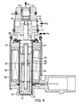
- a pressure-sensing section and a solenoid are arranged below the body 11. More specifically, on the lower end of the body 11, there is disposed an assembly formed by accommodating a plunger 22, a core 23, and a spring 24, as component elements of the solenoid, in a bottomed sleeve 21 forming a vacuum container. The opening of the bottomed sleeve 21 is sealed by a metal diaphragm 25. Outside of the bottomed sleeve 21, there are arranged a coil 26, a ring 27, a case 28, and a handle 29, all made of magnetic substances, for constituting a yoke for establishing a magnetic circuit.
- the core 23 is rigidly press-fitted in position, and the plunger 22 is axially movably disposed on the side of the core 23 facing toward the valve section.
- the plunger 22 is rigidly press-fitted on one end of a shaft 30 which extends axially movable through the centre of the core 23.
- the other end of the shaft 30 is supported by a bearing 31 which is slidably disposed in the core 23.
- a stop ring 32 for a spring-receiving member 33 is fitted on an intermediate portion of the shaft 30.
- a spring 24 is interposed between the spring-receiving member 33 and the bearing 31. The plunger 22 is urged by the spring 24 via the shaft 30 in a direction away from the core 23.
- the load of the spring 24 can be changed by externally adjusting the axial position of the bearing 31. More specifically, for the final adjustment after assembly of the control valve the bottom of the bottomed sleeve 21 is pushed from outside to be deformed inward, whereby the axial position of the bearing 31 abutting at the bottom is changed to adjust the load of the spring 24. Thus, the set point of the control valve is adjusted.
- the bottomed sleeve 21 is sealed by welding the diaphragm 25 to a flange portion formed on the open end of the bottomed sleeve 21.
- the diaphragm 25 first is placed on the flange portion and then is circumferentially welded to the flange portion along the entire perimeter by an annular patch 34 by laser welding, resistance welding, or the like, under vacuum atmosphere, such that the gastight assembly is formed with the interior maintained under vacuum.
- This assembly is fixed to the body 11 via a reinforcing ring 35 by positioning the flange portion of the bottomed sleeve 21 in a recess formed in the lower end of the body 11 and by caulking the peripheral wall of the recess. Then, the case 28 accommodating the coil 26 is fixed to the body 11 by caulking an upper end 36 of the case 28.
- an O-ring 37 is interposed between the patch 34 and the body 11 so as to seal between a chamber receiving the suction pressure Ps and the atmosphere, such that the centre of the solid part of the 0-ring 37 is positioned at a location radially inward of a weld line 38.
- stress generated by displacements of the diaphragm 25 is hindered from reaching the weld line 38 which may be fragile due to a material change caused by the welding process.
- the bottomed sleeve 21 is formed by deep-drawing from stainless steel material, e.g. of the specification SUS304.
- the bottomed sleeve 21 has to be formed of a non-magnetic material to prevent that the bottomed sleeve 21 attracts the plunger 22 during energization of the solenoid, because this would understandably increase the sliding resistance of the plunger 22.
- steel of the specification SUS304 has the property that it acquires magnetism due to a partial change in its metallic crystal structure when subjected to strong cold working. In such a case, the bottomed sleeve 21 is made non-magnetic again by an annealing step.
- the bottomed sleeve 21 also includes a portion which is desirably magnetic in view of the magnetic circuit.
- the portion is located in the area of the handle 29 which establishes a magnetic connection between the core 23 and the case 28.
- a part of the bottom-side portion of the bottomed sleeve 21 which is formed by deep drawing first with a straight extension, is further drawn as shown in detail in Fig. 3. More specifically, this part of the bottom-side portion of the bottomed sleeve 21 is subjected to strong cold working while its diameter is reduced such that it becomes magnetic to increase the magnetic permeability.
- This drawn part of the bottom-side portion of the bottomed sleeve 21 has its diameter reduced to form a press-fitting portion 39 used for rigidly press-fitting the core 23 in the bottomed sleeve 21.
- this press-fitting portion 39 the amount of press-fitting of the core 23 or its insertion depth, respectively, is adjusted to adjust the magnitude or width of a magnetic gap as defined between the core 23 and the plunger 22.
- the diaphragm 25 should also be made of a stainless steel, e.g. of a steel material for springs, e.g. of the specification SUS304CSP, in view of welding.
- the materials of the bottomed sleeve 21 and the diaphragm 25 are not limited to the mentioned stainless steel materials. It is also possible to use copper for the bottomed sleeve 21, and beryllium copper for the diaphragm 25.
- the ring 27, the case 28, and the handle 29 are formed of magnetic materials to serve as the yoke of the magnetic circuit of the solenoid. Magnetic lines of force generated by the coil 26 pass through the magnetic circuit formed by the case 28, the ring 27, the plunger 22, the core 23, and the handle 29.
- Fig. 1 the solenoid is de-energized and the suction pressure Ps is high, i.e. the air conditioner is not operating.
- the high suction pressure Ps displaces the diaphragm 25 downward against the load of the spring 24 to bring the plunger 22 into contact with the core 23.
- the valve element 16 held in contact with the diaphragm 25 via the shaft 17 is seated on the valve seat 15 by the spring 18.
- the valve section is in the fully-closed state.
- variable displacement compressor When the automotive air conditioner is started now (the compressor is driven by the engine) the variable displacement compressor is operated with maximum displacement.
- the compressor operating with maximum displacement lowers the suction pressure Ps sufficiently low to move the diaphragm 25, sensing the suction pressure Ps, upward.
- the plunger 22 moves away from the core 23 when still abutting at the diaphragm 25. If control current supplied to the solenoid coil 26 is set to a value of a cooling capacity corresponding to a temperature set for the air conditioning, the plunger 22 stops in a position where the suction pressure Ps, the loads of the springs 18 and 24, and the attractive force of the solenoid are balanced.
- the valve element 16 held in contact with the diaphragm 25 via the shaft 17 is pushed upward by the diaphragm 25 and leaves the valve seat 15 until it is set to a predetermined valve lift. Refrigerant at discharge pressure Pd is introduced into the crankcase at a flow rate according to the valve lift.
- the compressor operates with a displacement corresponding to the value of the control current.
- the diaphragm 25 senses the suction pressure Ps as an absolute pressure for controlling the valve lift.
- the suction pressure Ps When the refrigeration load increases, the suction pressure Ps will become higher, and the diaphragm 25 is displaced downward, so that the valve element 16 decreases the valve lift, causing the compressor to operate in a direction of increasing the displacement.
- the suction pressure Ps When the refrigeration load decreases, the suction pressure Ps will become lower and the diaphragm 25 is displaced upward to increase the valve lift, causing the compressor to operate in a direction of decreasing the displacement.
- the control valve controls the displacement of the compressor such that the suction pressure Ps becomes equal to a value set by the solenoid.
- present diaphragm 25 comprises three component parts.
- a base part 40 of the largest diameter with a central hole is welded to the flange portion of the bottomed sleeve 21.
- a funnel-shaped intermediate connecting part 41 is disposed on the base part 40.
- a disk 42 is disposed on the intermediate connecting part 41 to cover the upper opening of the port 41.
- the base part 40, the intermediate connecting part 41, and the disk 42 are formed e.g. of beryllium copper. Inner peripheral portions of the base part 40 and the intermediate connecting part 41 are welded to each other along the entire perimeters e.g.
- the bottomed sleeve 21 is formed of the same copper or copper beryllium material as the diaphragm 25.
- the base part 40 of the diaphragm 25 is welded to the flange portion of the bottomed sleeve 21 along the entire perimeter thereof under vacuum atmosphere e.g. by laser-welding.
- This diaphragm 25 can perform with a larger displacement stroke than the diaphragm of the first embodiment, in order to expand the control range of the valve section.
Landscapes
- Engineering & Computer Science (AREA)
- General Engineering & Computer Science (AREA)
- Mechanical Engineering (AREA)
- Compressors, Vaccum Pumps And Other Relevant Systems (AREA)
- Control Of Positive-Displacement Pumps (AREA)
- Magnetically Actuated Valves (AREA)
Applications Claiming Priority (2)
| Application Number | Priority Date | Filing Date | Title |
|---|---|---|---|
| JP2004097964A JP4257248B2 (ja) | 2004-03-30 | 2004-03-30 | 可変容量圧縮機用制御弁 |
| JP2004097964 | 2004-03-30 |
Publications (2)
| Publication Number | Publication Date |
|---|---|
| EP1582743A2 true EP1582743A2 (de) | 2005-10-05 |
| EP1582743A3 EP1582743A3 (de) | 2006-12-20 |
Family
ID=34879943
Family Applications (1)
| Application Number | Title | Priority Date | Filing Date |
|---|---|---|---|
| EP05005894A Withdrawn EP1582743A3 (de) | 2004-03-30 | 2005-03-17 | Regelventil für einen Verdichter variabler Verdrängung |
Country Status (5)
| Country | Link |
|---|---|
| US (1) | US20050220631A1 (de) |
| EP (1) | EP1582743A3 (de) |
| JP (1) | JP4257248B2 (de) |
| KR (1) | KR20060044873A (de) |
| CN (1) | CN100378324C (de) |
Families Citing this family (9)
| Publication number | Priority date | Publication date | Assignee | Title |
|---|---|---|---|---|
| JP2006112271A (ja) * | 2004-10-13 | 2006-04-27 | Tgk Co Ltd | 可変容量圧縮機用制御弁 |
| JP4626808B2 (ja) * | 2005-04-26 | 2011-02-09 | 株式会社豊田自動織機 | 可変容量型クラッチレス圧縮機用の容量制御弁 |
| KR101028874B1 (ko) * | 2009-03-25 | 2011-04-12 | 주식회사 두원전자 | 용량가변형 압축기의 용량제어밸브 및 조립방법 |
| KR100947642B1 (ko) | 2009-09-22 | 2010-03-15 | 주식회사 인지플러스 | 가변 용량 압축기의 컨트롤 밸브 |
| JP2011252401A (ja) * | 2010-05-31 | 2011-12-15 | Shinhan Electro-Mechanics Co Ltd | 可変容量圧縮機の容量制御弁、およびこの容量制御弁の組み立て方法 |
| JP6149239B2 (ja) * | 2013-06-28 | 2017-06-21 | 株式会社テージーケー | 可変容量圧縮機用制御弁 |
| JP6600603B2 (ja) * | 2016-06-28 | 2019-10-30 | 株式会社不二工機 | 可変容量型圧縮機用制御弁及びその組立方法 |
| KR102692484B1 (ko) * | 2019-05-20 | 2024-08-07 | 현대자동차주식회사 | 차량의 공기조화 시스템, 공기조화 시스템용 전자제어밸브 및 공기조화 시스템의 제어방법 |
| CN112576762A (zh) * | 2019-09-27 | 2021-03-30 | 杭州三花研究院有限公司 | 电动阀 |
Family Cites Families (15)
| Publication number | Priority date | Publication date | Assignee | Title |
|---|---|---|---|---|
| US3831499A (en) * | 1972-08-16 | 1974-08-27 | Compressive Ind Inc | Gas pump employing electron beam welded bellows |
| JP2945748B2 (ja) * | 1990-11-16 | 1999-09-06 | サンデン株式会社 | 容量可変型揺動式圧縮機 |
| JP3088536B2 (ja) * | 1991-12-26 | 2000-09-18 | サンデン株式会社 | 可変容量型揺動式圧縮機 |
| US5577534A (en) * | 1995-06-02 | 1996-11-26 | Applied Power Inc. | Load sensing proportional pressure control valve |
| US6116269A (en) * | 1998-07-07 | 2000-09-12 | Fasco Controls Corporation | Solenoid pressure transducer |
| US6029703A (en) * | 1998-12-18 | 2000-02-29 | Borg-Warner Automotive, Inc. | Pressure solenoid control valve with flux shunt |
| JP3886290B2 (ja) * | 1999-04-27 | 2007-02-28 | 株式会社テージーケー | 容量可変圧縮機の容量制御装置 |
| US6688853B1 (en) * | 2001-01-08 | 2004-02-10 | Honeywell International Inc. | Control valve for regulating flow between two chambers relative to another chamber |
| JP4333042B2 (ja) * | 2001-02-20 | 2009-09-16 | 株式会社豊田自動織機 | 容量可変型圧縮機の制御弁 |
| JP2002260918A (ja) * | 2001-02-28 | 2002-09-13 | Toyota Industries Corp | 電磁アクチュエータ及び同電磁アクチュエータの製造方法並びに同電磁アクチュエータを用いた容量可変型圧縮機の制御弁 |
| JP4246975B2 (ja) * | 2002-02-04 | 2009-04-02 | イーグル工業株式会社 | 容量制御弁 |
| JP3911443B2 (ja) * | 2002-05-27 | 2007-05-09 | 太平洋工業株式会社 | 制御弁 |
| JP4002797B2 (ja) * | 2002-07-08 | 2007-11-07 | 太平洋工業株式会社 | 圧縮機の制御弁 |
| JP2004278511A (ja) * | 2002-10-23 | 2004-10-07 | Tgk Co Ltd | 可変容量圧縮機用制御弁 |
| JP4303637B2 (ja) * | 2004-03-12 | 2009-07-29 | 株式会社テージーケー | 可変容量圧縮機用制御弁 |
-
2004
- 2004-03-30 JP JP2004097964A patent/JP4257248B2/ja not_active Expired - Fee Related
-
2005
- 2005-03-17 EP EP05005894A patent/EP1582743A3/de not_active Withdrawn
- 2005-03-21 CN CNB2005100557779A patent/CN100378324C/zh not_active Expired - Fee Related
- 2005-03-28 US US11/090,213 patent/US20050220631A1/en not_active Abandoned
- 2005-03-29 KR KR1020050025711A patent/KR20060044873A/ko not_active Withdrawn
Also Published As
| Publication number | Publication date |
|---|---|
| EP1582743A3 (de) | 2006-12-20 |
| US20050220631A1 (en) | 2005-10-06 |
| CN100378324C (zh) | 2008-04-02 |
| CN1676927A (zh) | 2005-10-05 |
| KR20060044873A (ko) | 2006-05-16 |
| JP2005282470A (ja) | 2005-10-13 |
| JP4257248B2 (ja) | 2009-04-22 |
Similar Documents
| Publication | Publication Date | Title |
|---|---|---|
| EP1574711A2 (de) | Kontrollventil für einen verstellbaren Taumelscheibenkompressor | |
| JP7171616B2 (ja) | 容量制御弁及び容量制御弁の制御方法 | |
| US7381031B2 (en) | Control valve for variable displacement compressor | |
| EP1247981B1 (de) | Kontrollventil für Kompressoren mit variabler Fördermenge | |
| EP1650435A1 (de) | Regelventil für einen Verdichter variabler Verdrängung | |
| US6102668A (en) | Electromagnetic control valve | |
| EP1413752A1 (de) | Regelventil für Verdichter mit veränderlicher Verdrängung | |
| JP2011043102A (ja) | 可変容量圧縮機用制御弁 | |
| JPWO2019142931A1 (ja) | 容量制御弁 | |
| US7387501B2 (en) | Control valve for variable displacement compressor | |
| US20050220631A1 (en) | Control valve for variable displacement compressor | |
| KR20060050534A (ko) | 가변 용량 압축기용 제어 밸브 | |
| US6974311B2 (en) | Control valve | |
| US20060083625A1 (en) | Control valve for variable displacement compressor | |
| JP2006029304A (ja) | 可変容量圧縮機用制御弁 | |
| JP2001193640A (ja) | 容量可変型圧縮機用制御弁 | |
| JP2002213638A (ja) | 電磁制御弁 | |
| JP2005214117A (ja) | 可変容量圧縮機用制御弁 | |
| EP2963294B1 (de) | Regelventil für einen verdichter mit variabler verdrängung | |
| JP2007278138A (ja) | 可変容量圧縮機用制御弁及びその特性調整方法 | |
| JP2001349460A (ja) | 電磁制御弁 |
Legal Events
| Date | Code | Title | Description |
|---|---|---|---|
| PUAI | Public reference made under article 153(3) epc to a published international application that has entered the european phase |
Free format text: ORIGINAL CODE: 0009012 |
|
| AK | Designated contracting states |
Kind code of ref document: A2 Designated state(s): AT BE BG CH CY CZ DE DK EE ES FI FR GB GR HU IE IS IT LI LT LU MC NL PL PT RO SE SI SK TR |
|
| AX | Request for extension of the european patent |
Extension state: AL BA HR LV MK YU |
|
| PUAL | Search report despatched |
Free format text: ORIGINAL CODE: 0009013 |
|
| AK | Designated contracting states |
Kind code of ref document: A3 Designated state(s): AT BE BG CH CY CZ DE DK EE ES FI FR GB GR HU IE IS IT LI LT LU MC NL PL PT RO SE SI SK TR |
|
| AX | Request for extension of the european patent |
Extension state: AL BA HR LV MK YU |
|
| AKX | Designation fees paid | ||
| STAA | Information on the status of an ep patent application or granted ep patent |
Free format text: STATUS: THE APPLICATION IS DEEMED TO BE WITHDRAWN |
|
| 18D | Application deemed to be withdrawn |
Effective date: 20070621 |
|
| REG | Reference to a national code |
Ref country code: DE Ref legal event code: 8566 |