EP1582760A1 - Support de patin pour pinces de frein - Google Patents
Support de patin pour pinces de frein Download PDFInfo
- Publication number
- EP1582760A1 EP1582760A1 EP05006178A EP05006178A EP1582760A1 EP 1582760 A1 EP1582760 A1 EP 1582760A1 EP 05006178 A EP05006178 A EP 05006178A EP 05006178 A EP05006178 A EP 05006178A EP 1582760 A1 EP1582760 A1 EP 1582760A1
- Authority
- EP
- European Patent Office
- Prior art keywords
- pad holder
- bracket
- pad
- brake
- holder device
- Prior art date
- Legal status (The legal status is an assumption and is not a legal conclusion. Google has not performed a legal analysis and makes no representation as to the accuracy of the status listed.)
- Granted
Links
Images


Classifications
-
- F—MECHANICAL ENGINEERING; LIGHTING; HEATING; WEAPONS; BLASTING
- F16—ENGINEERING ELEMENTS AND UNITS; GENERAL MEASURES FOR PRODUCING AND MAINTAINING EFFECTIVE FUNCTIONING OF MACHINES OR INSTALLATIONS; THERMAL INSULATION IN GENERAL
- F16D—COUPLINGS FOR TRANSMITTING ROTATION; CLUTCHES; BRAKES
- F16D55/00—Brakes with substantially-radial braking surfaces pressed together in axial direction, e.g. disc brakes
- F16D55/02—Brakes with substantially-radial braking surfaces pressed together in axial direction, e.g. disc brakes with axially-movable discs or pads pressed against axially-located rotating members
- F16D55/22—Brakes with substantially-radial braking surfaces pressed together in axial direction, e.g. disc brakes with axially-movable discs or pads pressed against axially-located rotating members by clamping an axially-located rotating disc between movable braking members, e.g. movable brake discs or brake pads
- F16D55/224—Brakes with substantially-radial braking surfaces pressed together in axial direction, e.g. disc brakes with axially-movable discs or pads pressed against axially-located rotating members by clamping an axially-located rotating disc between movable braking members, e.g. movable brake discs or brake pads with a common actuating member for the braking members
- F16D55/2245—Brakes with substantially-radial braking surfaces pressed together in axial direction, e.g. disc brakes with axially-movable discs or pads pressed against axially-located rotating members by clamping an axially-located rotating disc between movable braking members, e.g. movable brake discs or brake pads with a common actuating member for the braking members in which the common actuating member acts on two levers carrying the braking members, e.g. tong-type brakes
Definitions
- the present invention relates to a pad holder device for brake calipers, especially for rail vehicles, with a right pad holder and a left Pad holder, between which a brake disc is mounted and the one Brackets are connected to each other.
- Disc brakes usually have a brake pad holder, which has a brake caliper is movable to press the brake pads against a brake disc.
- brake cylinder, brake caliper, brake caliper and brake pad holder be combined with brake pad to compact brake caliper units.
- brake pads or parallel holding devices used are usually hanging on brake pads or parallel holding devices used, with which a rotation of the pad holder is prevented but a change in distance is allowed.
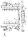
- Figure 1 is a parallel link of a Pad holder 1 shown, are provided on the brake pads 2, the inside are movable on a brake disc, not shown.
- the pad holder 1 comprises two guide rods 3, which have a cranked end, in a slotted guide 4 of a bracket 5 is added. This ensures that the Pad holder according to the slide guide 4 move towards each other. Instead of one Sliding guide 4 it is also known slideways for a linear movement to provide the pad holder.
- the bracket of the pad holder device is at least on one side with the pad holder in the manner of a parallel link on a tab with two Rotary axes connected.
- the mechanical guidance of the pad holder is essential less sensitive to dirt and freezing or jamming.
- the comparatively large bearing surfaces on the axes of rotation also ensure low wear and are also insensitive to vibration.
- the angle of the pad holders can be adjusted in a simple manner, in particular to avoid an oblique wear.
- the pad holder device thus formed is also simple and easy to move due to low friction moments.
- the bracket is hinged on both sides with a tab and this hinged connected to a pad holder.
- the pad holders are guided in the manner of a parallel link and can over the tab each pivoted and pressed at a predetermined angle to the brake disc become.
- the axes of rotation are through each formed a pivot pin.
- the bracket and the tabs against a be secured axial displacement.
- the tabs can be easily in the form of a flat iron with openings for the Rotary axes or through a bent sheet metal manufacture.
- the bracket is in the direction the axis of rotation formed elastically. Because with a certain wear of the coating or the brake disc can cause axial side movements and entanglement come to the pad holder, which then with a certain offset on the Brake disc are pressed. This offset can be due to an elasticity of the strap be compensated.
- the pad holders are preferred arranged substantially parallel to each other, but can also be in a given Angles are set to each other to prevent skew.
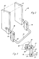
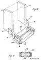
- a pad holder 10 includes a right pad holder 11 and a left pad Pad holder 12, which in the manner of a parallel link in each case via a tab 14th or 15 are hingedly connected to a bracket 13.
- the bracket 13 is c-shaped formed and ends 25 in a cylindrical opening of the tabs 14 and 15 respectively inserted.
- the tabs 14 and 15 are rotatably mounted about these ends 25.
- Spaced from the bracket 13 are pivot pins 18 in openings on the tabs 14 and 15 and the pad holders 11 and 12 inserted so that the tabs 14 and 15 are rotatably connected to the pad holders 11 and 12, respectively.
- the pad holder 12 is opposed to axial displacement the tab 15 secured.
- the tab 15 in the pivot pin 18 in the area the tab 15 has a groove 20 and in the region of the pad holder 12, a second groove 20th recessed, in each of which a locking pin 19 is inserted, wherein the locking pin 19 each partially on the pad holder 12 and the flap 15 and partially is received in the pivot pin 18.
- a brake caliper not shown or other mechanical actuating means are used to the pad holders 11 and 12 against each other to press and thus brake pads on one Let the brake disc act. Due to the articulated mounting of the pad holder 11 and 12 eliminates the need for a sliding guide in scenes or sliding bushings.
- FIG. 4 shows a modified embodiment of a pad holder device, in turn, a right pad holder 11 and a left pad holder 12th has, which are connected via a bracket 13 'together.
- the bracket 13 ' is L-shaped and with the right pad holder 11 only via a pivot pin 23 connected.
- the pivot pin 23 is connected to the pad holder 11.
- On the opposite Side is the bracket 13 'via a cranked pivot pin 15' with the left pad holder 12 connected.
- the cranked pivot pin 15 ' is with a End portion respectively rotatably connected to the pad holder 12 and the bracket 13 ', whereby two offset axes of rotation 16 and 17 are formed.
- the pad holder device 4 only three axes of rotation 16, 17 and 22 are thus formed and only on the left side of the bracket 13 'in the manner of a parallel link connected to the pad holder 12.
- FIG. 5 shows a third exemplary embodiment of a pad holding device, in which the pad holders 11 and 12 each have a cranked pivot pin 15 ' are connected to a flat iron formed as a bracket 13 " Connection of the cranked pivot pin 15 'with the pad holders 11 and 12 and the bracket 13 "may be formed according to Figure 3.
- the pad holders 11 and 12 each have two axes of rotation 17 and 16 and 22nd and 24 connected to the bracket 13 "in the manner of a parallel link.
- the hinge pins can play with it for a rotatable mounting of the pad holder 11 and 12 and the bracket 13 provide. This becomes a parallel guide tolerance achieved, which alternatively also by a conical bore or a conical Bolt can be obtained.
- the hinge pins can be cost-effective from a spring wire with a diameter be formed between 10 and 14 mm.
- the axial securing is by a Groove and a transverse pin reached, but it can also other mechanical Means are used for axial securing. It is also possible to use the hinged frame by a tension spring between the tabs 14 and 15 or by rubber rings in the joints to harness.
- the angle of the pad holders 11 and 12 to each other via suitable mechanical Medium be set.
- a unique Schrägverschl regimetendenz a Brake pads in a particular application can be caused by tilting the pad holder 11 and 12 are provided an optimized wear wear.
- FIG. 6 shows a further function of a pad holder device according to the invention vividly illustrated.
- the pad holders 11 and 12 of an inventive Pad holder means are mounted on levers 31 and 32, which are about axes of rotation 33rd and 34 are rotatable.
- trajectories 35 and 36 for the pad holder 12 and 11 given when pressed on the brake disc 30 and again be moved away from her.
- Due to non-parallel brake lever 31 and 32 through Increasing wear on the brake disc or brake pads occurs in Achsriosuiteioloen to an entanglement of the pad holders 11 and 12, so this offset by the amount H to each other on the brake disc 30 is pressed become. This displacement of the pad holder 11 and 12 must in the inventive Pad holder device are taken into account.
- the bracket of a pad holder device formed elastically to compensate for such displacement can.
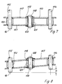
- One such bracket 113 is shown in FIG.
- the bracket has two plates 117, which are connected together centrally via a pin 118, which is a spacer sleeve 121 passes through and with a head 120, a spring 119 from the outside on the plates 117 presses.
- Laterally pivot pins 114 and 115 are provided, which are the two Pass through plates 117 and centered through a spacer sleeve 122 are performed.
- the bracket 113 compensate for this movement, as shown in Figure 8.
- the plates 117 are inclined and by the springs 119, the bracket 113 can be angled arrange against a certain bias so that the distance H bridges can be.
- the pivot pins 114 and 115 can thus be arranged offset from one another be without the hinge connection is otherwise impaired.
- Of the Bracket 113 can still be rotated about the pivot pins 114 and 115.
- Of the Bracket 113 is thus able to absorb the torsional moments of the pads and nevertheless allow a parallelogram shift.
- the bracket 113 can in a pad holder device according to the exemplary embodiments of FIGS to 5 are used.
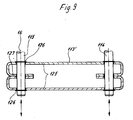
- FIG. 9 shows a further embodiment of an elastic strap 113 '.
- the bracket 113 ' comprises two curved plates 125, which in an edge region respectively C-shaped bent and have a leg 127 in the middle. In this Edge region of the bracket 113 is provided with a continuous opening, through a pivot pin 114 or 115 is performed. The pivot pin 115 or 114 is secured against axial displacement by circlips 126. Also this bracket 113 'can relative to a displacement of the pivot pins 114 and 115 still be rotated around each other, since the bent plates 125 a have corresponding elasticity.
- the Bracket 213 includes two U-shaped bent plates 216, in the end portions thereof each block 214 is fixed. In block 216, the axis of rotation 16 of the pivot pin 15 'recorded. The block 216 is via rivets 215 each with connected to the U-shaped plate 216.
- the bracket 213 thus formed has in turn a sufficient degree of elasticity and can easily in different Lengths are provided, instead of the providence of two Sheet metal 216 only a sheet metal can be mounted with longer legs.
- the invention is not limited to the illustrated embodiments. It For example, other mechanical means may be used to post a stirrup Type of parallel link with a pad holder 11 and 12 to connect.
Landscapes
- Engineering & Computer Science (AREA)
- General Engineering & Computer Science (AREA)
- Mechanical Engineering (AREA)
- Braking Arrangements (AREA)
Applications Claiming Priority (2)
| Application Number | Priority Date | Filing Date | Title |
|---|---|---|---|
| DE102004014188 | 2004-03-23 | ||
| DE102004014188A DE102004014188A1 (de) | 2004-03-23 | 2004-03-23 | Belaghaltereinrichtung für Bremszangen |
Publications (2)
| Publication Number | Publication Date |
|---|---|
| EP1582760A1 true EP1582760A1 (fr) | 2005-10-05 |
| EP1582760B1 EP1582760B1 (fr) | 2007-04-25 |
Family
ID=34877622
Family Applications (1)
| Application Number | Title | Priority Date | Filing Date |
|---|---|---|---|
| EP05006178A Expired - Lifetime EP1582760B1 (fr) | 2004-03-23 | 2005-03-22 | Support de patin pour pinces de frein |
Country Status (3)
| Country | Link |
|---|---|
| EP (1) | EP1582760B1 (fr) |
| AT (1) | ATE360766T1 (fr) |
| DE (2) | DE102004014188A1 (fr) |
Families Citing this family (1)
| Publication number | Priority date | Publication date | Assignee | Title |
|---|---|---|---|---|
| DE102017101028A1 (de) * | 2017-01-19 | 2018-07-19 | Knorr-Bremse Systeme für Schienenfahrzeuge GmbH | Bremszangeneinheit |
Citations (6)
| Publication number | Priority date | Publication date | Assignee | Title |
|---|---|---|---|---|
| DE1800595A1 (de) * | 1968-10-02 | 1970-05-27 | Krauss Maffei Ag | Scheibenbremsvorrichtung,insbesondere fuer Schienenfahrzeuge |
| DE2003341A1 (de) * | 1969-01-27 | 1971-04-01 | Ct De Rech S De Pont A Mousson | Scheibenbremse |
| DE2233180A1 (de) * | 1972-07-06 | 1974-01-24 | Mak Maschinenbau Gmbh | Scheibenbremse fuer seitenverschiebliche radsaetze von schienenfahrzeugen |
| DE2941128A1 (de) * | 1978-10-10 | 1980-04-24 | Lucas Industries Ltd | Scheibenbremse fuer schienenfahrzeuge |
| US4454932A (en) * | 1980-10-16 | 1984-06-19 | Sab Industri Ab | Suspension means for a rail vehicle disc brake unit |
| US5462139A (en) * | 1994-05-04 | 1995-10-31 | Gsi Engineering, Inc. | Cast bolt-on mounting bracket for supporting a disc brake on a railcar truck |
Family Cites Families (7)
| Publication number | Priority date | Publication date | Assignee | Title |
|---|---|---|---|---|
| US2590062A (en) * | 1946-07-05 | 1952-03-18 | American Steel Foundries | Brake head mounting |
| DE1675225B1 (de) * | 1968-01-31 | 1970-12-03 | Bremskerl Reibbelag Werke Emme | Zangen-Teilbelagscheibenbremse |
| DE2152316A1 (de) * | 1971-10-20 | 1973-04-26 | Knorr Bremse Gmbh | Verschluss zum festspannen eines in einen bremsbelagtraeger einschiebbaren bremsbelages |
| BE795613A (fr) * | 1972-03-18 | 1973-06-18 | Bergische Stahlindustrie | Porte-garniture de frein a levier de frein |
| DE19508034A1 (de) * | 1995-03-07 | 1996-09-12 | Knorr Bremse Systeme | Scheibenbremse für Fahrzeuge, insbesondere Schienenfahrzeuge |
| AT892U1 (de) * | 1995-09-07 | 1996-07-25 | Jenbacher Energiesysteme Ag | Scheibenbremse, insbesondere für schienenfahrzeuge |
| FR2811388B1 (fr) * | 2000-07-06 | 2002-09-13 | Arbel Fauvet Rail Sa | Dispositif de freinage sur les deux faces opposees d'une piece de revolution |
-
2004
- 2004-03-23 DE DE102004014188A patent/DE102004014188A1/de not_active Withdrawn
-
2005
- 2005-03-22 AT AT05006178T patent/ATE360766T1/de active
- 2005-03-22 DE DE502005000618T patent/DE502005000618D1/de not_active Expired - Lifetime
- 2005-03-22 EP EP05006178A patent/EP1582760B1/fr not_active Expired - Lifetime
Patent Citations (6)
| Publication number | Priority date | Publication date | Assignee | Title |
|---|---|---|---|---|
| DE1800595A1 (de) * | 1968-10-02 | 1970-05-27 | Krauss Maffei Ag | Scheibenbremsvorrichtung,insbesondere fuer Schienenfahrzeuge |
| DE2003341A1 (de) * | 1969-01-27 | 1971-04-01 | Ct De Rech S De Pont A Mousson | Scheibenbremse |
| DE2233180A1 (de) * | 1972-07-06 | 1974-01-24 | Mak Maschinenbau Gmbh | Scheibenbremse fuer seitenverschiebliche radsaetze von schienenfahrzeugen |
| DE2941128A1 (de) * | 1978-10-10 | 1980-04-24 | Lucas Industries Ltd | Scheibenbremse fuer schienenfahrzeuge |
| US4454932A (en) * | 1980-10-16 | 1984-06-19 | Sab Industri Ab | Suspension means for a rail vehicle disc brake unit |
| US5462139A (en) * | 1994-05-04 | 1995-10-31 | Gsi Engineering, Inc. | Cast bolt-on mounting bracket for supporting a disc brake on a railcar truck |
Also Published As
| Publication number | Publication date |
|---|---|
| ATE360766T1 (de) | 2007-05-15 |
| DE502005000618D1 (de) | 2007-06-06 |
| EP1582760B1 (fr) | 2007-04-25 |
| DE102004014188A1 (de) | 2005-10-13 |
Similar Documents
| Publication | Publication Date | Title |
|---|---|---|
| DE102009038317B4 (de) | Verstellbare Lenksäule für ein Kraftfahrzeug | |
| DE102012002734A1 (de) | Belaghaltesystem einer Scheibenbremse eines Kraftfahrzeugs | |
| EP0698749A2 (fr) | Actionneur de frein à disque | |
| DE19936280B4 (de) | Türscharniersystem | |
| EP1809921B1 (fr) | Plaquette d'un frein a disque | |
| WO2010086088A1 (fr) | Assemblage d'une garniture de frein avec un porte- garniture | |
| DE102010019470B4 (de) | Scheibenbremse für ein Nutzfahrzeug sowie Bremsbelag für eine Scheibenbremse | |
| DE69700942T2 (de) | Scheibenbremsvorrichtung | |
| EP3953601A1 (fr) | Dispositif de rappel de garnitures de freins et frein à disque | |
| DE4304616A1 (de) | Scheibenbremse für die Räder eines Kraftfahrzeuges | |
| DE2931071C2 (de) | Kombinierte Niederhalte-Spreizfeder | |
| EP2823193B1 (fr) | Unité de freinage pour un véhicule et véhicule pourvu d'une telle unité de freinage | |
| DE69132360T2 (de) | Bremsbackenhalterung für scheibenbremsenaggregat | |
| DE29821113U1 (de) | Bremsbelag | |
| EP1582760B1 (fr) | Support de patin pour pinces de frein | |
| DE4407293C1 (de) | Bremszange für Scheibenbremsen von Schienenfahrzeugen | |
| DE3123640A1 (de) | "aufhaengevorrichtung fuer bewegliche teile von insbesondere an schienenfahrzeugen angeordneten scheibenbremsen" | |
| DE3232759A1 (de) | Teilbelag-scheibenbremse | |
| EP0747609B1 (fr) | Frein à disque à garniture partielle | |
| EP1279853B1 (fr) | Support de patin de frein | |
| DE102014006954A1 (de) | Führungseinrichtung für eine Schwimmsattel-Scheibenbremse | |
| DE19651633C1 (de) | Druckplattenbaugruppe für eine Kraftfahrzeug-Reibungskupplung mit automatischem Spielausgleich | |
| DE2910118C3 (de) | Mechanische Betätigungsvorrichtung für eine Teilbelag-Scheibenbremse | |
| DE3023333A1 (de) | Bremsbackenhalterung fuer scheibenbremsen | |
| DE3833734C2 (de) | Schwimmsattel-Teilbelag-Scheibenbremse, insbesondere für Kraftfahrzeuge |
Legal Events
| Date | Code | Title | Description |
|---|---|---|---|
| PUAI | Public reference made under article 153(3) epc to a published international application that has entered the european phase |
Free format text: ORIGINAL CODE: 0009012 |
|
| AK | Designated contracting states |
Kind code of ref document: A1 Designated state(s): AT BE BG CH CY CZ DE DK EE ES FI FR GB GR HU IE IS IT LI LT LU MC NL PL PT RO SE SI SK TR |
|
| AX | Request for extension of the european patent |
Extension state: AL BA HR LV MK YU |
|
| 17P | Request for examination filed |
Effective date: 20060405 |
|
| AKX | Designation fees paid |
Designated state(s): AT BE BG CH CY CZ DE DK EE ES FI FR GB GR HU IE IS IT LI LT LU MC NL PL PT RO SE SI SK TR |
|
| GRAP | Despatch of communication of intention to grant a patent |
Free format text: ORIGINAL CODE: EPIDOSNIGR1 |
|
| GRAS | Grant fee paid |
Free format text: ORIGINAL CODE: EPIDOSNIGR3 |
|
| GRAA | (expected) grant |
Free format text: ORIGINAL CODE: 0009210 |
|
| AK | Designated contracting states |
Kind code of ref document: B1 Designated state(s): AT BE BG CH CY CZ DE DK EE ES FI FR GB GR HU IE IS IT LI LT LU MC NL PL PT RO SE SI SK TR |
|
| PG25 | Lapsed in a contracting state [announced via postgrant information from national office to epo] |
Ref country code: FI Free format text: LAPSE BECAUSE OF FAILURE TO SUBMIT A TRANSLATION OF THE DESCRIPTION OR TO PAY THE FEE WITHIN THE PRESCRIBED TIME-LIMIT Effective date: 20070425 |
|
| REG | Reference to a national code |
Ref country code: GB Ref legal event code: FG4D Free format text: NOT ENGLISH |
|
| REG | Reference to a national code |
Ref country code: IE Ref legal event code: FG4D Free format text: LANGUAGE OF EP DOCUMENT: GERMAN |
|
| REG | Reference to a national code |
Ref country code: CH Ref legal event code: EP Ref country code: CH Ref legal event code: NV Representative=s name: ISLER & PEDRAZZINI AG |
|
| REF | Corresponds to: |
Ref document number: 502005000618 Country of ref document: DE Date of ref document: 20070606 Kind code of ref document: P |
|
| REG | Reference to a national code |
Ref country code: HU Ref legal event code: AG4A Ref document number: E001589 Country of ref document: HU |
|
| PG25 | Lapsed in a contracting state [announced via postgrant information from national office to epo] |
Ref country code: ES Free format text: LAPSE BECAUSE OF FAILURE TO SUBMIT A TRANSLATION OF THE DESCRIPTION OR TO PAY THE FEE WITHIN THE PRESCRIBED TIME-LIMIT Effective date: 20070805 |
|
| REG | Reference to a national code |
Ref country code: SE Ref legal event code: TRGR |
|
| ET | Fr: translation filed | ||
| PG25 | Lapsed in a contracting state [announced via postgrant information from national office to epo] |
Ref country code: IS Free format text: LAPSE BECAUSE OF FAILURE TO SUBMIT A TRANSLATION OF THE DESCRIPTION OR TO PAY THE FEE WITHIN THE PRESCRIBED TIME-LIMIT Effective date: 20070825 |
|
| PG25 | Lapsed in a contracting state [announced via postgrant information from national office to epo] |
Ref country code: PT Free format text: LAPSE BECAUSE OF FAILURE TO SUBMIT A TRANSLATION OF THE DESCRIPTION OR TO PAY THE FEE WITHIN THE PRESCRIBED TIME-LIMIT Effective date: 20070925 |
|
| REG | Reference to a national code |
Ref country code: CH Ref legal event code: PCAR Free format text: ISLER & PEDRAZZINI AG;POSTFACH 1772;8027 ZUERICH (CH) |
|
| NLV1 | Nl: lapsed or annulled due to failure to fulfill the requirements of art. 29p and 29m of the patents act | ||
| GBV | Gb: ep patent (uk) treated as always having been void in accordance with gb section 77(7)/1977 [no translation filed] |
Effective date: 20070425 |
|
| PG25 | Lapsed in a contracting state [announced via postgrant information from national office to epo] |
Ref country code: PL Free format text: LAPSE BECAUSE OF FAILURE TO SUBMIT A TRANSLATION OF THE DESCRIPTION OR TO PAY THE FEE WITHIN THE PRESCRIBED TIME-LIMIT Effective date: 20070425 |
|
| REG | Reference to a national code |
Ref country code: IE Ref legal event code: FD4D |
|
| PLAZ | Examination of admissibility of opposition: despatch of communication + time limit |
Free format text: ORIGINAL CODE: EPIDOSNOPE2 |
|
| PLBI | Opposition filed |
Free format text: ORIGINAL CODE: 0009260 |
|
| PLAQ | Examination of admissibility of opposition: information related to despatch of communication + time limit deleted |
Free format text: ORIGINAL CODE: EPIDOSDOPE2 |
|
| PG25 | Lapsed in a contracting state [announced via postgrant information from national office to epo] |
Ref country code: DK Free format text: LAPSE BECAUSE OF FAILURE TO SUBMIT A TRANSLATION OF THE DESCRIPTION OR TO PAY THE FEE WITHIN THE PRESCRIBED TIME-LIMIT Effective date: 20070425 Ref country code: NL Free format text: LAPSE BECAUSE OF FAILURE TO SUBMIT A TRANSLATION OF THE DESCRIPTION OR TO PAY THE FEE WITHIN THE PRESCRIBED TIME-LIMIT Effective date: 20070425 Ref country code: IE Free format text: LAPSE BECAUSE OF FAILURE TO SUBMIT A TRANSLATION OF THE DESCRIPTION OR TO PAY THE FEE WITHIN THE PRESCRIBED TIME-LIMIT Effective date: 20070425 Ref country code: SI Free format text: LAPSE BECAUSE OF FAILURE TO SUBMIT A TRANSLATION OF THE DESCRIPTION OR TO PAY THE FEE WITHIN THE PRESCRIBED TIME-LIMIT Effective date: 20070425 Ref country code: BG Free format text: LAPSE BECAUSE OF FAILURE TO SUBMIT A TRANSLATION OF THE DESCRIPTION OR TO PAY THE FEE WITHIN THE PRESCRIBED TIME-LIMIT Effective date: 20070725 |
|
| 26 | Opposition filed |
Opponent name: FAIVELEY TRANSPORT REMSCHEID GMBH Effective date: 20080121 |
|
| PLAX | Notice of opposition and request to file observation + time limit sent |
Free format text: ORIGINAL CODE: EPIDOSNOBS2 |
|
| PG25 | Lapsed in a contracting state [announced via postgrant information from national office to epo] |
Ref country code: SK Free format text: LAPSE BECAUSE OF FAILURE TO SUBMIT A TRANSLATION OF THE DESCRIPTION OR TO PAY THE FEE WITHIN THE PRESCRIBED TIME-LIMIT Effective date: 20070425 Ref country code: LT Free format text: LAPSE BECAUSE OF FAILURE TO SUBMIT A TRANSLATION OF THE DESCRIPTION OR TO PAY THE FEE WITHIN THE PRESCRIBED TIME-LIMIT Effective date: 20070425 |
|
| PG25 | Lapsed in a contracting state [announced via postgrant information from national office to epo] |
Ref country code: GB Free format text: LAPSE BECAUSE OF FAILURE TO SUBMIT A TRANSLATION OF THE DESCRIPTION OR TO PAY THE FEE WITHIN THE PRESCRIBED TIME-LIMIT Effective date: 20070425 Ref country code: GR Free format text: LAPSE BECAUSE OF FAILURE TO SUBMIT A TRANSLATION OF THE DESCRIPTION OR TO PAY THE FEE WITHIN THE PRESCRIBED TIME-LIMIT Effective date: 20070726 |
|
| PG25 | Lapsed in a contracting state [announced via postgrant information from national office to epo] |
Ref country code: RO Free format text: LAPSE BECAUSE OF FAILURE TO SUBMIT A TRANSLATION OF THE DESCRIPTION OR TO PAY THE FEE WITHIN THE PRESCRIBED TIME-LIMIT Effective date: 20070425 |
|
| PLBB | Reply of patent proprietor to notice(s) of opposition received |
Free format text: ORIGINAL CODE: EPIDOSNOBS3 |
|
| BERE | Be: lapsed |
Owner name: KNORR-BREMSE SYSTEME FUR SCHIENENFAHRZEUGE G.M.B. Effective date: 20080331 |
|
| PG25 | Lapsed in a contracting state [announced via postgrant information from national office to epo] |
Ref country code: MC Free format text: LAPSE BECAUSE OF NON-PAYMENT OF DUE FEES Effective date: 20080331 |
|
| PG25 | Lapsed in a contracting state [announced via postgrant information from national office to epo] |
Ref country code: EE Free format text: LAPSE BECAUSE OF FAILURE TO SUBMIT A TRANSLATION OF THE DESCRIPTION OR TO PAY THE FEE WITHIN THE PRESCRIBED TIME-LIMIT Effective date: 20070425 |
|
| PG25 | Lapsed in a contracting state [announced via postgrant information from national office to epo] |
Ref country code: BE Free format text: LAPSE BECAUSE OF NON-PAYMENT OF DUE FEES Effective date: 20080331 |
|
| PG25 | Lapsed in a contracting state [announced via postgrant information from national office to epo] |
Ref country code: CY Free format text: LAPSE BECAUSE OF FAILURE TO SUBMIT A TRANSLATION OF THE DESCRIPTION OR TO PAY THE FEE WITHIN THE PRESCRIBED TIME-LIMIT Effective date: 20070425 |
|
| PG25 | Lapsed in a contracting state [announced via postgrant information from national office to epo] |
Ref country code: LU Free format text: LAPSE BECAUSE OF NON-PAYMENT OF DUE FEES Effective date: 20080322 |
|
| PG25 | Lapsed in a contracting state [announced via postgrant information from national office to epo] |
Ref country code: TR Free format text: LAPSE BECAUSE OF FAILURE TO SUBMIT A TRANSLATION OF THE DESCRIPTION OR TO PAY THE FEE WITHIN THE PRESCRIBED TIME-LIMIT Effective date: 20070425 |
|
| REG | Reference to a national code |
Ref country code: FR Ref legal event code: PLFP Year of fee payment: 12 |
|
| PLAB | Opposition data, opponent's data or that of the opponent's representative modified |
Free format text: ORIGINAL CODE: 0009299OPPO |
|
| R26 | Opposition filed (corrected) |
Opponent name: FAIVELEY TRANSPORT WITTEN GMBH Effective date: 20080121 |
|
| PLCK | Communication despatched that opposition was rejected |
Free format text: ORIGINAL CODE: EPIDOSNREJ1 |
|
| STAA | Information on the status of an ep patent application or granted ep patent |
Free format text: STATUS: THE PATENT HAS BEEN GRANTED |
|
| REG | Reference to a national code |
Ref country code: DE Ref legal event code: R100 Ref document number: 502005000618 Country of ref document: DE |
|
| REG | Reference to a national code |
Ref country code: FR Ref legal event code: PLFP Year of fee payment: 13 |
|
| PLBN | Opposition rejected |
Free format text: ORIGINAL CODE: 0009273 |
|
| STAA | Information on the status of an ep patent application or granted ep patent |
Free format text: STATUS: OPPOSITION REJECTED |
|
| 27O | Opposition rejected |
Effective date: 20170202 |
|
| REG | Reference to a national code |
Ref country code: FR Ref legal event code: PLFP Year of fee payment: 14 |
|
| PGFP | Annual fee paid to national office [announced via postgrant information from national office to epo] |
Ref country code: CH Payment date: 20190325 Year of fee payment: 15 Ref country code: FR Payment date: 20190326 Year of fee payment: 15 Ref country code: IT Payment date: 20190321 Year of fee payment: 15 Ref country code: CZ Payment date: 20190312 Year of fee payment: 15 Ref country code: DE Payment date: 20190325 Year of fee payment: 15 |
|
| PGFP | Annual fee paid to national office [announced via postgrant information from national office to epo] |
Ref country code: AT Payment date: 20190319 Year of fee payment: 15 Ref country code: SE Payment date: 20190325 Year of fee payment: 15 Ref country code: HU Payment date: 20190311 Year of fee payment: 15 |
|
| REG | Reference to a national code |
Ref country code: DE Ref legal event code: R119 Ref document number: 502005000618 Country of ref document: DE |
|
| PG25 | Lapsed in a contracting state [announced via postgrant information from national office to epo] |
Ref country code: CZ Free format text: LAPSE BECAUSE OF NON-PAYMENT OF DUE FEES Effective date: 20200322 |
|
| REG | Reference to a national code |
Ref country code: CH Ref legal event code: PL |
|
| REG | Reference to a national code |
Ref country code: AT Ref legal event code: MM01 Ref document number: 360766 Country of ref document: AT Kind code of ref document: T Effective date: 20200322 |
|
| PG25 | Lapsed in a contracting state [announced via postgrant information from national office to epo] |
Ref country code: FR Free format text: LAPSE BECAUSE OF NON-PAYMENT OF DUE FEES Effective date: 20200331 Ref country code: HU Free format text: LAPSE BECAUSE OF NON-PAYMENT OF DUE FEES Effective date: 20200323 Ref country code: DE Free format text: LAPSE BECAUSE OF NON-PAYMENT OF DUE FEES Effective date: 20201001 Ref country code: LI Free format text: LAPSE BECAUSE OF NON-PAYMENT OF DUE FEES Effective date: 20200331 Ref country code: CH Free format text: LAPSE BECAUSE OF NON-PAYMENT OF DUE FEES Effective date: 20200331 Ref country code: SE Free format text: LAPSE BECAUSE OF NON-PAYMENT OF DUE FEES Effective date: 20200323 Ref country code: AT Free format text: LAPSE BECAUSE OF NON-PAYMENT OF DUE FEES Effective date: 20200322 |
|
| PG25 | Lapsed in a contracting state [announced via postgrant information from national office to epo] |
Ref country code: IT Free format text: LAPSE BECAUSE OF NON-PAYMENT OF DUE FEES Effective date: 20200322 |