EP1583119B1 - Verriegelingssystem für einen Linearantrieb - Google Patents
Verriegelingssystem für einen Linearantrieb Download PDFInfo
- Publication number
- EP1583119B1 EP1583119B1 EP20050102351 EP05102351A EP1583119B1 EP 1583119 B1 EP1583119 B1 EP 1583119B1 EP 20050102351 EP20050102351 EP 20050102351 EP 05102351 A EP05102351 A EP 05102351A EP 1583119 B1 EP1583119 B1 EP 1583119B1
- Authority
- EP
- European Patent Office
- Prior art keywords
- rod
- locking system
- movement
- translation
- balls
- Prior art date
- Legal status (The legal status is an assumption and is not a legal conclusion. Google has not performed a legal analysis and makes no representation as to the accuracy of the status listed.)
- Expired - Lifetime
Links
- 230000000694 effects Effects 0.000 claims description 4
- 230000003100 immobilizing effect Effects 0.000 description 3
- 230000003993 interaction Effects 0.000 description 3
- 125000006850 spacer group Chemical group 0.000 description 3
- 230000006835 compression Effects 0.000 description 2
- 238000007906 compression Methods 0.000 description 2
- 230000000903 blocking effect Effects 0.000 description 1
- 238000005096 rolling process Methods 0.000 description 1
Images


Classifications
-
- H—ELECTRICITY
- H01—ELECTRIC ELEMENTS
- H01H—ELECTRIC SWITCHES; RELAYS; SELECTORS; EMERGENCY PROTECTIVE DEVICES
- H01H3/00—Mechanisms for operating contacts
- H01H3/22—Power arrangements internal to the switch for operating the driving mechanism
- H01H3/30—Power arrangements internal to the switch for operating the driving mechanism using spring motor
- H01H3/3031—Means for locking the spring in a charged state
-
- H—ELECTRICITY
- H01—ELECTRIC ELEMENTS
- H01H—ELECTRIC SWITCHES; RELAYS; SELECTORS; EMERGENCY PROTECTIVE DEVICES
- H01H3/00—Mechanisms for operating contacts
- H01H3/22—Power arrangements internal to the switch for operating the driving mechanism
- H01H3/30—Power arrangements internal to the switch for operating the driving mechanism using spring motor
- H01H3/3052—Linear spring motors
-
- H—ELECTRICITY
- H01—ELECTRIC ELEMENTS
- H01H—ELECTRIC SWITCHES; RELAYS; SELECTORS; EMERGENCY PROTECTIVE DEVICES
- H01H3/00—Mechanisms for operating contacts
- H01H3/22—Power arrangements internal to the switch for operating the driving mechanism
- H01H3/30—Power arrangements internal to the switch for operating the driving mechanism using spring motor
- H01H3/3031—Means for locking the spring in a charged state
- H01H2003/3036—Means for locking the spring in a charged state using of balls or rollers in the locking device
Definitions
- the present invention relates to a locking system for immobilizing or releasing the translation movement of a rod of a linear control, the rod being movable in an axial direction between a first position and a second position spaced a certain distance according to the axial direction of the first position.
- the invention more particularly relates to a locking system for a linear mechanical spring control used to move the moving contact crew of a high or medium voltage circuit breaker.
- the two positions of the rod of the linear control correspond to the two positions of the movable contact equipment of the circuit breaker.
- the first position of the rod corresponds to the position of the moving contact crew when the circuit breaker is open and the second position of the rod corresponds to the position of the moving contact crew when the circuit breaker is closed.
- the translation movement of the rod in the axial direction is maintained by springs and in particular helical springs which serve to store the kinetic energy to perform successive switching of the circuit breaker.
- Patent document is known US2003 / 0034331 , a linear control of the type indicated above with a locking system to immobilize or release the translation movement of the rod.
- This locking system is constituted by a pawl controlled by an electric coil.
- a snap locking system is not suitable for spring loaded controls with springs exerting significant forces on the rod.
- this type of locking system is not adapted to lock the position of the rod in both directions of movement of the rod in the axial direction.
- the object of the invention is to provide a locking system for immobilizing or releasing the translational movement of a rod of a linear control for high or medium voltage circuit breaker for example, which is reliable and fast and which supports axial forces the rod during switching operations of the circuit-breaker.
- the subject of the invention is a locking system for immobilizing or releasing the translational movement of a rod of a linear control, the rod being movable in an axial direction between a first position and a second position spaced apart by a certain distance in the axial direction of the first position, characterized in that it comprises two circumferential grooves formed on the rod and spaced from each other in the axial direction of said certain distance and a plurality of balls distributed over the periphery of the rod to cooperate with said circumferential grooves, said balls being mounted in an annular cage surrounding the rod, said annular cage comprising a first annular portion fixed in the axial direction, surrounding the rod and traversed by the balls and a second movable portion relative to the fixed annular portion, surrounding the first annular portion with the balls and ag enco rotational or translationally driven relative to the first annular portion under the effect of an axial force exerted on the rod to release the translational movement of the rod.
- the cage is arranged so that a rotational movement of the mobile part around the rod in a first angular direction causes the release of the translation movement of the rod. in one direction and a rotational movement of the moving part around the rod in a reverse direction causes immobilization of the translation movement of the rod.
- the cage is arranged so that a translational movement in the axial direction of the movable part in a first direction causes the release of the translation movement of the rod. and that a translational movement of the movable part in a reverse direction causes immobilization of the translation movement of the rod.
- the mobile part comprises grooves in which the balls are introduced when the moving part occupies an angular position which causes the release of the translational movement of the rod and wherein the movable portion has between two consecutive grooves an inner surface which forms a ramp on which the balls move.
- the mobile part comprises a circumferential groove in which the balls are introduced when the movable part occupies a position in the axial direction A which causes the release of the movement of translation of the rod and wherein a flank of the circumferential groove is interrupted to extend into a frustoconical bore which forms a ramp on which the balls move.
- the circumferential grooves have inclined flanks with respect to the axis of the rod.
- the mobile part is immobilized and mobilized by means of an electromagnet.
- the locking system comprises a return spring which opposes the rotational movement or translation of the movable part.
- an axial force exerted on the rod of the linear control creates a torque by the interaction of the balls on the inclined sides of the grooves and on the ramps between the grooves of the cage which tends to drive the mobile part of the cage in a rotary movement around the rod so that it is sufficient to release the rotary movement of the movable part of the cage to release the translational movement of the rod.
- the release of the translation movement of the rod can be performed in both directions of the axial direction and this quickly with little energy.
- the figure 1 shows very schematically a linear mechanical control springs fitted to a high-voltage circuit breaker and provided with a locking system according to the invention.
- the figure 2 shows in an enlarged way the linear mechanical control with springs of the figure 1 with the locking system according to a first embodiment of the invention.
- the figure 3 is a partial schematic sectional view along AA on the figure 4 of the annular cage of the locking system according to a first embodiment of the invention.
- the figure 4 is a radial sectional view of the annular cage of the locking system according to a first embodiment of the invention.
- the figure 5 is an enlarged view in radial section of a portion of the cage of the locking system according to a first embodiment of the invention.
- the figure 6 schematically illustrates the locking system with an electromagnet for blocking the rotary movement of the annular cage according to a first embodiment of the invention.
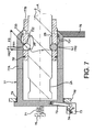
- the figure 7 is a partial schematic sectional view along the axial direction A of the locking system according to a second embodiment of the invention.
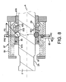
- the figure 8 illustrates a schematic partial sectional view along the axial direction A of the locking system according to a third embodiment of the invention.
- FIG. 1 very schematically, an example of application of the locking system according to the invention for a linear mechanical control springs fitted to a high-voltage circuit breaker 1.
- the circuit breaker 1 is shown here in the open position.
- the rod 2 of the linear mechanical control 3 is integral in motion of the movable contact 4 of the circuit breaker 1 which is separated here from the fixed contact of the circuit breaker.
- the locking system 5 blocks the translational movement of the rod 2 in the axial direction A.
- the figure 2 is an enlargement of the linear spring control 3 shown on the figure 1 according to a first embodiment of the invention.
- the rod 2 is provided with two circumferential grooves 2A, 2B spaced apart from one another in the axial direction A by a distance corresponding to the distance traveled by the rod 2 when it is displaced between a first position corresponding to the closing position of the circuit breaker and a second position corresponding to the opening position of the circuit breaker.
- the locking system 5 is shown according to the first embodiment. However, it will be seen later that a locking system according to a second and a third embodiment of the invention can be applied to the linear control 3.
- the locking system 5 comprises a plurality of balls 6 distributed over the circular periphery of the rod 2 to cooperate with one of the grooves 2A or 2B of the rod.
- the balls 6 are mounted in an annular cage 7 fixed via a disk 8 to the tubular housing 9 of the control 3.
- two bearing discs 10 and 11 are fixedly mounted in the axial direction A, being spaced apart from each other in the axial direction A, between the two springs 3A and 3B. These two disks 10, 11 are engaged in the tubular housing 9 of the control 3. Furthermore, two other support discs 12, 13 are arranged on either side of the pair of disks 10 and 11 in the direction axial A, these discs 12, 13 being integral and movable in the axial direction A with the rod 2.
- the two springs 3A, 3B are helical springs which are arranged coaxially with respect to each other around the rod 2
- the trip spring 3A which is disposed here between the locking system 5 and the spring 3B, is maintained between the discs 10 and 12 while the engagement spring 3B is held between the discs 11 and 13.
- the interengagement spring 3B maintained compressed between the disks 11 and 13 exerts on the rod 2 an axial force which tends to move the rod 2 in the axial direction upwards on the figure 2 so that a loosening of the locking system 5 (release of the balls 6 of the groove 2B) will cause the switching of the circuit breaker 1 in the closed position parallel to the compression of the spring 3A between the discs 10 and 12.
- the groove 2A is in front of the locking system 5 which can be operated as described below to lock the translational movement of the rod.
- the figure 3 illustrates a partial schematic sectional view along AA on the figure 4 of the annular cage 7 of a first embodiment of the locking system 5 according to the invention.
- the annular cage 7 comprises a first ring-shaped annular portion 7A which is rotatable about a second annular ring-shaped fixed portion 7B, the latter surrounding the rod 2 and is integral with the control box 9 via the disc 8 (not shown in this figure).
- the rotatable annular portion 7A is disposed between a circumferential outer rib 7B 'of the fixed annular portion 7B and a set of clamping rings 7B "which abut the annular portion 7A against the rib 7B'.
- the annular portion 7B comprises a set of radial holes 7C 'in which are housed respectively the balls 6.
- the balls 6 are engaged both in the holes 7C 'and in the groove 2B to immobilize the movement of the rod 2 in the axial direction A.
- the circumferential groove 2B (like the groove 2A) has flanks 2B 'which are not perpendicular with respect to the axis of the rod 2 but which are inclined by an angle ⁇ (of the order of 60 °) by relative to the axis of the rod 2. More particularly, in section the groove forms a U whose branches flare towards the opening of the U so as to form each a sort of ramp for the balls 6.
- the arrow FS is shown the force exerted by the engagement spring 3B on the rod 2.
- the arrow FR1 represents a radial reaction force exerted on each ball 6 by the inclined flank 2B 'of the groove 2B. It is understood that the direction of the force FR1 is perpendicular to the axial direction A.
- FIG 4 a schematic radial sectional view of the annular cage 7 of the locking system 5 according to the first embodiment of the invention is shown, in which the fixed annular portion 7B and the annular mobile ring portion 7A are seen.
- the movable annular portion 7A comprises splines 30 distributed on the inner periphery whose number is identical to the number of balls 6 and in each of which a ball is retracted to clear the circumferential groove 2B (or the groove 2A).
- Each groove extends perpendicular to the axis of the rod 2.
- Each groove 30 extends perpendicularly to the axis of the rod 2.
- the depth of the grooves 30 is slightly greater than the depth of the groove 2B (or throat 2A).
- each groove has a U-shaped cross-section, the branches of the "U” flaring towards the opening of the "U". More particularly, each groove has two flanks 31 which are inclined relative to a radial direction of an angle of 30 °, for example.
- the junction zone between two consecutive grooves on the inner surface of the movable annular part 7A also defines a kind of ramp 32 which rises on the inside of the part 7A of the cage to join the edge of a inclined side 31 of a groove 30 (the left flank on the figure 5 ).
- the ramp 32 is arranged so that the axial reaction force FR1, transmitted via each of the balls 6 to the corresponding ramp 32, generates a tangential component FR2. The latter tends to impose a rotational movement on the mobile part 7A of the annular cage 7.
- the direction of the force FR2 is the line perpendicular to the direction of FR1.
- the force FR2 is applied to the point of contact between the ball 6 and the corresponding ramp 32.
- said ramp is an inclined plane of angle ⁇ (of a few degrees) with respect to the line perpendicular to the direction of FR1.
- ⁇ of a few degrees
- the balls 6 are held in the holes of the part 7B on one side by the groove 2B (or 2A) and on the other by the ramp 32.
- the ramp 32 could not not have a flat surface.
- the combination of all the FR2 forces produced by the balls 6 on the ramps 32 is a pair MR2 which acts to rotate the movable portion 7A of the annular cage 7 in the direction indicated by the arrow MR2 (trigonometric direction).
- MR2 trigonometric direction
- the rotation of the movable portion 7A of the annular cage 7 in the direction of MR2 causes the balls 6 to coincide with the splines 30, which allows the balls 6 to be released from the groove 2B and thus release the movement in translation of the rod 2.
- an electromagnet 40 and a return spring 41 are respectively used to block the rotational movement of the portion 7A of the annular cage and to return to a locking position this portion 7A of the annular cage .
- the electromagnet 40 is fixed to a frame 42 disposed inside the housing 9 and comprises for example a "U" shaped magnet 43, a rotating part 44 arranged in the air gap of the magnet, a finger 45 and a return spring 46.
- the mobile part 7A of the annular cage 7 has a radial handle on its outer periphery whose end is in abutment against the workpiece 44.
- the torque MR2 exerted on the annular cage is indicated on the figure 6 and it is seen that the return spring 41 exerts a force on the handle of the movable part 7A which opposes the MR2 pair.
- the piece 44 is locked in position, pressing the support of the electromagnet on one side and pulled by the return spring 46 on the other side.
- the part 44 In response to an electrical pulse applied to the magnet 43, the part 44 is rotated in the air gap of the magnet 43, which consequently releases the rotary movement of the annular cage 7 in the trigonometrical direction indicated by the arrow MR2.
- the rotation of the annular cage in the direction of MR2 causes a rise of the balls 6 in the grooves 30 and thus the release of the translational movement of the rod 2. This results in a circuit breaker switching in a closed position. In this position of the circuit breaker, the annular cage 7 surrounds the annular groove 2A.
- the locking system 5 operates in the same way for switching the circuit breaker from a closed position to an open position.
- an axial force exerted on the rod of the linear control creates a torque by the interaction of the balls on the inclined sides of the grooves of the rod and on the ramp in the extension of a flank of the groove of the movable part which tends to drive the moving part of the cage in a translation movement in the axial direction so that it is sufficient to release the translational movement of the movable part of the cage to release the translational movement of the rod.
- the release of the translation movement of the rod can be performed in both directions of the axial direction and this quickly with little energy.
- the figure 7 illustrates a schematic partial sectional view along the axial direction A of the locking system according to a second embodiment of the invention.
- the locking system according to the second embodiment of the invention is applied to a mechanical spring drive for a high and medium voltage circuit breaker as described in the first embodiment and illustrated above by the figures 1 and 2 .
- the rod 2 of the control is shown with the grooves 2A and 2B.
- the locking system 5 here comprises an annular cage 77 surrounding the rod 2 and in which the balls 6 are arranged.
- the annular cage 77 comprises a ring-shaped fixed annular portion 77B having radial holes distributed over its circular periphery in which are the annular portion 77B is attached to the housing 9 (not shown on the figure 7 )
- the annular cage 77 also comprises a cylindrical sleeve shaped annular portion 77A fitted on the end of the rod 2 and surrounding the annular ring-shaped portion 77B.
- the part in sleeve form 77A is movable in the axial direction A.
- the sleeve-shaped movable portion 77A includes an inner circumferential groove 730 that surrounds the fixed ring 77B and wherein the plurality of balls 6 retract when the movable bushing 77A occupies a certain position along the axis A corresponding to the release of the translation movement of the rod 2.
- the depth of the groove 730 is slightly greater than the depth of the groove 2B (or the groove 2A).
- This groove 730 has flanks 731 inclined at an angle of 30 °, for example, with respect to a radial direction.
- One of the flanks 731 is interrupted to extend into a frustoconical bore which tapers toward the axis A towards the bottom of the movable bushing 77A to form an annular ramp 732.
- said ramp 732 is a plane inclined a few degrees with respect to the axial direction A and a function similar to the plane 32 on the figure 5 .
- the plurality of balls 6 is engaged, on one side, in the groove 2B and maintained on the other by the ramp 732.
- the rod 2 of the control is thus maintained in the stationary position.
- the arrow FS is shown the force exerted by the engagement spring 3B on the rod 2.
- the arrow FR1 represents the reaction force transmitted through the plurality of balls 6 to the movable sleeve 77A. It is understood that the direction of the force FR1 is the radial direction at the point of contact between the corresponding ball 6 and the ramp 732.
- This force FR1 is thus applied to the ramp 732 so that it generates an axial force FR2 'acting to cause the translational movement of the movable sleeve 77A in the opposite direction of the force FS of the engagement spring 3B.
- This translational movement of the movable bushing 77A is blocked by an electromagnet 73, similar to that of the first embodiment and fixed to the housing 9 (not shown in FIG. figure 7 ).
- the electromagnet 73 controls, by means of a rotating part 74, the rotation of a rod-shaped rod 75 mounted on a pivot and connected by an oblong hole to the movable bushing 77A, so that Rotation of the rotating part 74 causes, via the rod 75, the release of the translational movement of the movable sleeve 77A driven under the effect of the force FR2 '.
- the balls 6 then move in the holes of the fixed ring 77B and retract in the groove 730 of the movable sleeve 77A.
- the rod 2 is released and undergoes a translation movement driven by the force FS. This results in a circuit breaker switching in the closed position.
- the groove 730 of the movable sleeve 77A faces the circumferential groove 2A.
- a return spring 71 disposed coaxially with the rod 2 between an abutment 76, integral with the housing 9, and the outer bottom of the bushing 77A, acts to return the latter to the position of immobilization of the rod, that is to say in the direction of the FS force.
- the bottom of the mobile socket 77A is widened so as to abut on a disc 76 ', integral with the housing 9, thus limiting its stroke in the direction of the force FS.
- the disc 76 ' surrounds and guides the movable sleeve 77A through a spacer 79 with a low coefficient of friction.
- a second spacer 79 'with a low coefficient of friction secured to the fixed ring 77B guides and facilitates the sliding of the movable sleeve 77A.
- the balls 6 move in the holes of the fixed ring 77B and retract into the groove 2A of the rod 2, pushed by the ramps 731 and 732 of the movable sleeve 77A.
- the electromagnet acts to hold still the rod 2 of the control in this closed position of the circuit breaker.
- the locking system according to the second embodiment operates in a similar manner for switching the circuit breaker from a closed position to an open position.
- an axial force exerted on the rod of the linear control creates a torque by the interaction of the balls on the inclined flanks of the grooves of the rod and on the ramp in the extension of a flank of the groove of the movable part which tends to drive the mobile part of the cage in a translation movement in the axial direction so that it is sufficient to release the translational movement of the moving part of the cage to release the translational movement of the rod.
- the release of the translation movement of the rod can be made in both directions of the axial direction and this quickly with little energy.
- the figure 8 illustrates a schematic partial sectional view along the axial direction A of the locking system according to a third embodiment of the invention.
- the locking system according to the third embodiment of the invention is applied to a mechanical spring drive for a high and medium voltage circuit breaker as described in the first embodiment and illustrated above by the figures 1 and 2 .
- the rod 2 of the control is shown with the grooves 2A and 2B.
- the locking system 5 here comprises an annular cage 87 surrounding the rod 2 and in which the balls 6 are arranged.
- the annular cage 87 comprises a ring-shaped first annular portion 87B having radial holes distributed over its circular periphery in which the balls 6 are arranged.
- the annular portion 87B is fixed to the casing 9 (not shown in FIG. figure 8 ) by means not shown on the figure 8 .
- the annular cage 87 also comprises a second ring-shaped cylindrical movable portion 87A surrounding the fixed annular portion 87B.
- the cylindrical movable portion 87A is movable in translation in the axial direction A.
- a third fixed portion 84 in the form of an open bottom sleeve surrounds the movable portion 87A.
- the bushing 84 fitted by the end of the rod 2 has its bottom open to allow the rod 2 to pass during its movement. translation and is integral with the fixed annular portion 87B.
- the movable ring 87A is provided with an inner circumferential groove 830 which surrounds the fixed ring 87B and in which the plurality of balls 6 retract when the movable ring 87A occupies a certain position along the axis A corresponding to the release the translation movement of the rod 2.
- the depth of the groove 830 is slightly greater than the depth of the groove 2B (or the groove 2A).
- This groove 830 has flanks 831 inclined at an angle of 30 °, for example, with respect to a radial direction.
- One of the flanks 831 is interrupted to extend into a frustoconical bore which tapers towards the axis A going towards the bottom of the bushing 84 to form an annular ramp 832.
- said ramp 832 is a inclined plane of a few degrees with respect to the axial direction A.
- An annular spacer 83 with a low coefficient of friction fixed to the fixed ring 87B promotes the sliding of the movable ring 87A.
- the plurality of balls 6 is engaged, on one side, in the groove 2B and maintained on the other by the ramp 832.
- the control rod 2 is thus maintained in the stationary position.
- the arrow FS is shown the force exerted by the engagement spring 3B on the rod 2.
- the arrow FR1 represents the reaction force transmitted through the plurality of balls 6 to the movable ring 87A.
- the direction of the FR1 force is the radial direction at the point of contact between the corresponding ball 6 and the ramp 832.
- This force FR1 is therefore applied to the ramp 832 so that it generates an axial force FR2 'acting to drive the translational movement of the movable sleeve 87A in the opposite direction of the force FS of the engagement spring 3B.
- This translational movement of the movable bushing 87A is blocked by an electromagnet (not shown on the figure 8 ) fixed to the housing 9.
- the open-bottomed bushing 84 comprises an opening arranged to allow an "L" -shaped rod 85 connected to the movable ring 87A to move.
- the connecting rod 85 is connected outside the cage 87A to the electromagnet (not shown on the figure 8 ) by means of a rotating part (not shown on the figure 8 ), so that a rotation of the latter causes, via the connecting rod 85, the release of the translational movement of the movable ring 87A driven under the effect of the force FR2 '.
- the balls 6 then move in the holes of the fixed ring 87B and retract in the groove 830 of the movable ring 87A.
- the rod 2 is released and undergoes a translational movement driven by the force FS. This results in a circuit breaker switching in the closed position.
- the groove 830 of the movable ring 87A faces the circumferential groove 2A.
- the balls 6 move in the holes of the fixed ring 87B and retract into the groove 2A of the rod 2, pushed by the ramps 831 and 832 of the movable ring 87A.
- the electromagnet acts to hold still the rod 2 of the control in this closed position of the circuit breaker.
- the locking system according to the third embodiment operates in a similar manner for switching the circuit breaker from a closed position to an open position.
- the locking system according to the invention can be applied to a linear mechanical spring control for high or medium voltage disconnector or to a linear mechanical control with springs for high or medium voltage earthing switches.
- the linear electrical equipment 14 for driving and controlling the movement of the control rod 2 may be, for example, a servomotor connected to a rack. It is possible to replace the springs of the control completely and to control and control the movement of the rod by this servomotor only.
- the angle of inclination of the flanks of the grooves 2A, 2B and 32, 732, 832 planes may be chosen so as to obtain a rolling of the balls in the annular cage rather than sliding.
Landscapes
- Driving Mechanisms And Operating Circuits Of Arc-Extinguishing High-Tension Switches (AREA)
- Bearings For Parts Moving Linearly (AREA)
- Transmission Devices (AREA)
Claims (11)
- Verriegelungssystem zum Blockieren bzw. Freigeben der Verschiebebewegung einer Stange (2) eines Linearantriebs, wobei die Stange in einer axialen Richtung (A) zwischen einer ersten Position und einer zweiten Position verstellbar ist, die in einem bestimmten Abstand in axialer Richtung von der ersten Position entfernt liegt, dadurch gekennzeichnet, dass es zwei Umfangsnuten (2A, 2B) aufweist, die an der Stange ausgebildet sind und in dem einen bestimmten Abstand in axialer Richtung voneinander entfernt liegen, sowie eine Mehrzahl von Kugeln (6), die über den Umfang der Stange verteilt sind, um mit den Umfangsnuten zusammenzuwirken, wobei die Kugeln in einem die Stange umgebenden ringförmigen Käfig (7, 77, 87) gelagert sind, wobei der ringförmige Käfig einen ersten Ringabschnitt (7B, 77B, 87B) aufweist, der in axialer Richtung fest ist, die Stange umgibt und von den Kugeln durchsetzt wird, und einen zweiten Abschnitt (7A, 77A, 87A), der bezüglich des festen Ringabschnitts (7B, 77B, 87B) beweglich ist, den ersten Ringabschnitt mit den Kugeln umgibt und so angeordnet ist, dass er unter der Wirkung einer auf die Stange ausgeübten axialen Kraft drehend oder translatorisch bezüglich des ersten Ringabschnitts mitgenommen wird, um die Verschiebebewegung der Stange freizugeben.
- Verriegelungssystem nach Anspruch 1, wobei der Käfig (7) so angeordnet ist, dass eine Drehbewegung des beweglichen Abschnitts (7A) in einer ersten Winkelrichtung um die Stange herum die Freigabe der Verschiebebewegung der Stange in einer Richtung bewirkt und dass eine Drehbewegung des beweglichen Abschnitts (7A) in einer umgekehrten Richtung um die Stange herum das Blockieren der Verschiebebewegung der Stange bewirkt.
- Verriegelungssystem nach Anspruch 1, wobei der Käfig (77, 87) so angeordnet ist, dass eine Verschiebebewegung des beweglichen Abschnitts (77A, 87A) in einer ersten Richtung in Axialrichtung die Freigabe der Verschiebebewegung der Stange bewirkt und eine Verschiebebewegung des beweglichen Abschnitts (77A, 87A) in umgekehrter Richtung das Blockieren der Verschiebebewegung der Stange bewirkt.
- Verriegelungssystem nach Anspruch 2, wobei der bewegliche Abschnitt (7B) Riffelungen (30) aufweist, in welche sich die Kugeln (6) dann einzügen, wenn der bewegliche Abschnitt eine Winkelstellung einnimmt, welche die Freigabe der Verschiebebewegung der Stange bewirkt, und wobei der bewegliche Abschnitt zwischen zwei aufeinanderfolgenden Riffelungen eine Innenfläche aufweist, die eine Rampe (32) bildet, auf welcher sich die Kugeln bewegen.
- Verriegelungssystem nach Anspruch 2, wobei der bewegliche Abschnitt (77A, 87A) eine Umfangsnut (730, 830) aufweist, in welche sich die Kugeln (6) dann einfügen, wenn der bewegliche Abschnitt eine Stellung in axialer Richtung A einnimmt, welche die Freigabe der Verschiebebewegung der Stange bewirkt, und wobei eine Flanke der Umfangsnut (730, 830) unterbrochen wird, um sich in eine kegelstumpfförmige Bohrung fortzusetzen, welche eine Rampe (732, 832) bildet, auf welche sich die Kugeln bewegen.
- Verriegelungssystem nach einem der Ansprüche 1 bis 5, wobei die Umfangsnuten (2A, 2B) der Stange Flanken aufweisen, die bezüglich der Achse der Stange geneigt verlaufen.
- Verriegelungssystem nach den Ansprüchen 1 bis 6, wobei der bewegliche Abschnitt (7A, 77A, 87A) mittels eines Elektromagneten (40, 70) blockiert wird.
- Verriegelungssystem nach den Ansprüchen 1 bis 7, enthaltend eine Rückstellfeder (41, 71, 81), welche eine Kraft in einer Richtung entgegengesetzt zur Dreh- bzw. Verschiebebewegung des beweglichen Abschnitts (7A, 77A, 87A) ausübt.
- Mechanischer Linearantrieb für Hoch- bzw. Mittelspannungsausschalter mit einem Verriegelungssystem nach einem der Ansprüche 1 bis 8.
- Mechanischer Linearantrieb für Hoch- bzw. Mittelspannungstrennsehalter mit einem Verriegelungssystem nach einem der Ansprüche 1 bis 8.
- Mechanischer Linearantrieb für Hoch- bzw. Mittelspannungs-Erdungstrennschalter mit einem Verriegelungssystem nach einem der Ansprüche 1 bis 8.
Applications Claiming Priority (2)
| Application Number | Priority Date | Filing Date | Title |
|---|---|---|---|
| FR0450611 | 2004-03-29 | ||
| FR0450611A FR2868198B1 (fr) | 2004-03-29 | 2004-03-29 | Systeme de verrouillage pour une commande lineaire |
Publications (3)
| Publication Number | Publication Date |
|---|---|
| EP1583119A2 EP1583119A2 (de) | 2005-10-05 |
| EP1583119A3 EP1583119A3 (de) | 2008-03-05 |
| EP1583119B1 true EP1583119B1 (de) | 2009-07-15 |
Family
ID=34878493
Family Applications (1)
| Application Number | Title | Priority Date | Filing Date |
|---|---|---|---|
| EP20050102351 Expired - Lifetime EP1583119B1 (de) | 2004-03-29 | 2005-03-23 | Verriegelingssystem für einen Linearantrieb |
Country Status (3)
| Country | Link |
|---|---|
| EP (1) | EP1583119B1 (de) |
| DE (1) | DE602005015372D1 (de) |
| FR (1) | FR2868198B1 (de) |
Families Citing this family (8)
| Publication number | Priority date | Publication date | Assignee | Title |
|---|---|---|---|---|
| ATE463039T1 (de) * | 2005-07-13 | 2010-04-15 | Siemens Ag | Antriebsmechanismus und schaltverfahren für ein schaltgerät |
| FR2971080B1 (fr) | 2011-02-02 | 2013-03-01 | Alstom Grid Sas | Appareillage d'ampoule a vide comprenant un moyen de verrouillage |
| FR2971079B1 (fr) * | 2011-02-02 | 2013-03-01 | Alstom Grid Sas | Appareillage electrique comprenant une partie mobile a dynamique amelioree |
| EP2654056A1 (de) * | 2012-04-17 | 2013-10-23 | ABB Technology AG | Notfallöffnungsvorrichtung |
| WO2019145017A1 (en) * | 2018-01-23 | 2019-08-01 | Renesas Electronics Corporation | Over-temperature protection circuit |
| EP3671794B1 (de) * | 2018-12-20 | 2023-02-08 | ABB Schweiz AG | Mittelspannungsschaltpol |
| DE102021206036A1 (de) * | 2021-06-14 | 2022-12-15 | MAGENTA GmbH Mechatronische und Kinematische Systeme | Auslöseeinrichtung und Anordnung mit einer Auslöseeinrichtung |
| CN113898689A (zh) * | 2021-11-11 | 2022-01-07 | 鞍山电磁阀有限责任公司 | 驱动齿条锁紧装置 |
Family Cites Families (4)
| Publication number | Priority date | Publication date | Assignee | Title |
|---|---|---|---|---|
| US3008479A (en) * | 1959-02-10 | 1961-11-14 | Altair Inc | Valves |
| NL163050C (nl) * | 1976-06-23 | 1980-07-15 | Hazemeijer Bv | Veeraandrijfmechanisme voor een elektrische schakelaar. |
| FR2714522B1 (fr) * | 1993-12-27 | 1996-02-02 | Gec Alsthom T & D Sa | Dispositif de commande linéaire pour disjoncteur. |
| WO2001037297A1 (en) * | 1999-11-13 | 2001-05-25 | S & C Electric Company | Circuit interrupter and operating mechanism therefor |
-
2004
- 2004-03-29 FR FR0450611A patent/FR2868198B1/fr not_active Expired - Fee Related
-
2005
- 2005-03-23 DE DE200560015372 patent/DE602005015372D1/de not_active Expired - Lifetime
- 2005-03-23 EP EP20050102351 patent/EP1583119B1/de not_active Expired - Lifetime
Also Published As
| Publication number | Publication date |
|---|---|
| EP1583119A2 (de) | 2005-10-05 |
| FR2868198A1 (fr) | 2005-09-30 |
| EP1583119A3 (de) | 2008-03-05 |
| FR2868198B1 (fr) | 2006-05-19 |
| DE602005015372D1 (de) | 2009-08-27 |
Similar Documents
| Publication | Publication Date | Title |
|---|---|---|
| EP1583119B1 (de) | Verriegelingssystem für einen Linearantrieb | |
| FR2865492A1 (fr) | Ensemble de verrouillage, notamment d'un element mobile de fermeture, et combinaison l'utilisant | |
| EP1648008B1 (de) | Schaltgerät mit Frontbedienung oder Seitenbedienung | |
| EP0768469A1 (de) | Schnellspannbefestigungsvorrichtung auf einem Gewindeschaft zum Drehantrieb | |
| CH405728A (fr) | Tambour rotatif commandé par une manivelle repliable | |
| EP2545573B1 (de) | Hybrid-leistungsschalter unter verwendung eines schalters mit rückstellung an einem abschluss | |
| EP1709655B1 (de) | Bistabile betätigungsvorrichtung einer bewegbaren, nicht durchgehenden, welle und damit versehener schalter für batterie | |
| EP2398029B1 (de) | Schalter mit monostabiler Bedienung und bistabilem Kontakt | |
| FR2793945A1 (fr) | Sectionneur haute tension a contact mobile deplace a grande vitesse | |
| EP2168867A1 (de) | Teleskopischer Stellantrieb mit Haupt- und Hilstriebstange | |
| FR2757585A1 (fr) | Limiteur mecanique de force pour verin electrique lineaire a vis | |
| FR2655187A1 (fr) | Mobile d'actionnement a cle pour interrupteur de securite. | |
| WO2000030136A1 (fr) | Detecteur de position avec mecanisme d'orientation | |
| EP0895260A1 (de) | Schnelle Steuervorrichtung für eine Hochspannungs Schaltvorrichtung, insbesondere Erdungsschalter | |
| EP2068332B1 (de) | Verriegelungsgerät für einen Steuerungsmechanismus eines elektrischen Getätes, und Steuerungsmechanismus mit solchem Verriegelungsgerät | |
| FR2759869A1 (fr) | Dispositif de protection cephalique, notamment casque integral de moto | |
| EP1746301A1 (de) | Sattel einer elektromechanischen Scheibenbremse | |
| FR3144387A1 (fr) | Contacteur de puissance normalement fermé | |
| EP4253786B1 (de) | Elektromagnetische bremsvorrichtung, konfiguriert zum blockieren einer rotierenden welle, und mobilitätssystem, das die vorrichtung und die drehwelle besteht | |
| FR2916542A1 (fr) | Mecanisme de commande a levier basculant et a configurations multiples,et application | |
| EP1213730B1 (de) | Verbesserungen für elektrische Schaltvorrichtungen | |
| FR3148864A1 (fr) | Mécanisme de commande d'un dispositif de coupure du courant | |
| EP0663499A1 (de) | Schlüssel für ein Zylinderschloss und ein Zylinderschloss für einen solchen Schlüssel | |
| FR2992248A1 (fr) | Systeme de machine-outil portative | |
| FR2853762A1 (fr) | Dispositif de manoeuvre bistable d'un arbre mobile en translation |
Legal Events
| Date | Code | Title | Description |
|---|---|---|---|
| PUAI | Public reference made under article 153(3) epc to a published international application that has entered the european phase |
Free format text: ORIGINAL CODE: 0009012 |
|
| AK | Designated contracting states |
Kind code of ref document: A2 Designated state(s): AT BE BG CH CY CZ DE DK EE ES FI FR GB GR HU IE IS IT LI LT LU MC NL PL PT RO SE SI SK TR |
|
| AX | Request for extension of the european patent |
Extension state: AL BA HR LV MK YU |
|
| PUAL | Search report despatched |
Free format text: ORIGINAL CODE: 0009013 |
|
| AK | Designated contracting states |
Kind code of ref document: A3 Designated state(s): AT BE BG CH CY CZ DE DK EE ES FI FR GB GR HU IE IS IT LI LT LU MC NL PL PT RO SE SI SK TR |
|
| AX | Request for extension of the european patent |
Extension state: AL BA HR LV MK YU |
|
| 17P | Request for examination filed |
Effective date: 20080821 |
|
| AKX | Designation fees paid |
Designated state(s): AT BE BG CH CY CZ DE DK EE ES FI FR GB GR HU IE IS IT LI LT LU MC NL PL PT RO SE SI SK TR |
|
| GRAP | Despatch of communication of intention to grant a patent |
Free format text: ORIGINAL CODE: EPIDOSNIGR1 |
|
| GRAS | Grant fee paid |
Free format text: ORIGINAL CODE: EPIDOSNIGR3 |
|
| GRAA | (expected) grant |
Free format text: ORIGINAL CODE: 0009210 |
|
| AK | Designated contracting states |
Kind code of ref document: B1 Designated state(s): AT BE BG CH CY CZ DE DK EE ES FI FR GB GR HU IE IS IT LI LT LU MC NL PL PT RO SE SI SK TR |
|
| REG | Reference to a national code |
Ref country code: CH Ref legal event code: EP Ref country code: GB Ref legal event code: FG4D Free format text: NOT ENGLISH |
|
| REG | Reference to a national code |
Ref country code: IE Ref legal event code: FG4D |
|
| REF | Corresponds to: |
Ref document number: 602005015372 Country of ref document: DE Date of ref document: 20090827 Kind code of ref document: P |
|
| NLV1 | Nl: lapsed or annulled due to failure to fulfill the requirements of art. 29p and 29m of the patents act | ||
| PG25 | Lapsed in a contracting state [announced via postgrant information from national office to epo] |
Ref country code: LT Free format text: LAPSE BECAUSE OF FAILURE TO SUBMIT A TRANSLATION OF THE DESCRIPTION OR TO PAY THE FEE WITHIN THE PRESCRIBED TIME-LIMIT Effective date: 20090715 Ref country code: IS Free format text: LAPSE BECAUSE OF FAILURE TO SUBMIT A TRANSLATION OF THE DESCRIPTION OR TO PAY THE FEE WITHIN THE PRESCRIBED TIME-LIMIT Effective date: 20091115 Ref country code: AT Free format text: LAPSE BECAUSE OF FAILURE TO SUBMIT A TRANSLATION OF THE DESCRIPTION OR TO PAY THE FEE WITHIN THE PRESCRIBED TIME-LIMIT Effective date: 20090715 Ref country code: ES Free format text: LAPSE BECAUSE OF FAILURE TO SUBMIT A TRANSLATION OF THE DESCRIPTION OR TO PAY THE FEE WITHIN THE PRESCRIBED TIME-LIMIT Effective date: 20091026 Ref country code: FI Free format text: LAPSE BECAUSE OF FAILURE TO SUBMIT A TRANSLATION OF THE DESCRIPTION OR TO PAY THE FEE WITHIN THE PRESCRIBED TIME-LIMIT Effective date: 20090715 Ref country code: SE Free format text: LAPSE BECAUSE OF FAILURE TO SUBMIT A TRANSLATION OF THE DESCRIPTION OR TO PAY THE FEE WITHIN THE PRESCRIBED TIME-LIMIT Effective date: 20090715 |
|
| REG | Reference to a national code |
Ref country code: IE Ref legal event code: FD4D |
|
| PG25 | Lapsed in a contracting state [announced via postgrant information from national office to epo] |
Ref country code: SI Free format text: LAPSE BECAUSE OF FAILURE TO SUBMIT A TRANSLATION OF THE DESCRIPTION OR TO PAY THE FEE WITHIN THE PRESCRIBED TIME-LIMIT Effective date: 20090715 Ref country code: PL Free format text: LAPSE BECAUSE OF FAILURE TO SUBMIT A TRANSLATION OF THE DESCRIPTION OR TO PAY THE FEE WITHIN THE PRESCRIBED TIME-LIMIT Effective date: 20090715 Ref country code: NL Free format text: LAPSE BECAUSE OF FAILURE TO SUBMIT A TRANSLATION OF THE DESCRIPTION OR TO PAY THE FEE WITHIN THE PRESCRIBED TIME-LIMIT Effective date: 20090715 |
|
| PG25 | Lapsed in a contracting state [announced via postgrant information from national office to epo] |
Ref country code: PT Free format text: LAPSE BECAUSE OF FAILURE TO SUBMIT A TRANSLATION OF THE DESCRIPTION OR TO PAY THE FEE WITHIN THE PRESCRIBED TIME-LIMIT Effective date: 20091115 Ref country code: BG Free format text: LAPSE BECAUSE OF FAILURE TO SUBMIT A TRANSLATION OF THE DESCRIPTION OR TO PAY THE FEE WITHIN THE PRESCRIBED TIME-LIMIT Effective date: 20091015 |
|
| PG25 | Lapsed in a contracting state [announced via postgrant information from national office to epo] |
Ref country code: RO Free format text: LAPSE BECAUSE OF FAILURE TO SUBMIT A TRANSLATION OF THE DESCRIPTION OR TO PAY THE FEE WITHIN THE PRESCRIBED TIME-LIMIT Effective date: 20090715 Ref country code: DK Free format text: LAPSE BECAUSE OF FAILURE TO SUBMIT A TRANSLATION OF THE DESCRIPTION OR TO PAY THE FEE WITHIN THE PRESCRIBED TIME-LIMIT Effective date: 20090715 Ref country code: CZ Free format text: LAPSE BECAUSE OF FAILURE TO SUBMIT A TRANSLATION OF THE DESCRIPTION OR TO PAY THE FEE WITHIN THE PRESCRIBED TIME-LIMIT Effective date: 20090715 Ref country code: IE Free format text: LAPSE BECAUSE OF FAILURE TO SUBMIT A TRANSLATION OF THE DESCRIPTION OR TO PAY THE FEE WITHIN THE PRESCRIBED TIME-LIMIT Effective date: 20090715 Ref country code: EE Free format text: LAPSE BECAUSE OF FAILURE TO SUBMIT A TRANSLATION OF THE DESCRIPTION OR TO PAY THE FEE WITHIN THE PRESCRIBED TIME-LIMIT Effective date: 20090715 |
|
| PLBE | No opposition filed within time limit |
Free format text: ORIGINAL CODE: 0009261 |
|
| STAA | Information on the status of an ep patent application or granted ep patent |
Free format text: STATUS: NO OPPOSITION FILED WITHIN TIME LIMIT |
|
| PG25 | Lapsed in a contracting state [announced via postgrant information from national office to epo] |
Ref country code: SK Free format text: LAPSE BECAUSE OF FAILURE TO SUBMIT A TRANSLATION OF THE DESCRIPTION OR TO PAY THE FEE WITHIN THE PRESCRIBED TIME-LIMIT Effective date: 20090715 |
|
| 26N | No opposition filed |
Effective date: 20100416 |
|
| BERE | Be: lapsed |
Owner name: AREVA T&D A.G. Effective date: 20100331 |
|
| PG25 | Lapsed in a contracting state [announced via postgrant information from national office to epo] |
Ref country code: GR Free format text: LAPSE BECAUSE OF FAILURE TO SUBMIT A TRANSLATION OF THE DESCRIPTION OR TO PAY THE FEE WITHIN THE PRESCRIBED TIME-LIMIT Effective date: 20091016 Ref country code: MC Free format text: LAPSE BECAUSE OF NON-PAYMENT OF DUE FEES Effective date: 20100331 |
|
| GBPC | Gb: european patent ceased through non-payment of renewal fee |
Effective date: 20100323 |
|
| PG25 | Lapsed in a contracting state [announced via postgrant information from national office to epo] |
Ref country code: BE Free format text: LAPSE BECAUSE OF NON-PAYMENT OF DUE FEES Effective date: 20100331 |
|
| PG25 | Lapsed in a contracting state [announced via postgrant information from national office to epo] |
Ref country code: GB Free format text: LAPSE BECAUSE OF NON-PAYMENT OF DUE FEES Effective date: 20100323 Ref country code: IT Free format text: LAPSE BECAUSE OF FAILURE TO SUBMIT A TRANSLATION OF THE DESCRIPTION OR TO PAY THE FEE WITHIN THE PRESCRIBED TIME-LIMIT Effective date: 20090715 |
|
| PG25 | Lapsed in a contracting state [announced via postgrant information from national office to epo] |
Ref country code: CY Free format text: LAPSE BECAUSE OF FAILURE TO SUBMIT A TRANSLATION OF THE DESCRIPTION OR TO PAY THE FEE WITHIN THE PRESCRIBED TIME-LIMIT Effective date: 20090715 |
|
| PG25 | Lapsed in a contracting state [announced via postgrant information from national office to epo] |
Ref country code: HU Free format text: LAPSE BECAUSE OF FAILURE TO SUBMIT A TRANSLATION OF THE DESCRIPTION OR TO PAY THE FEE WITHIN THE PRESCRIBED TIME-LIMIT Effective date: 20100116 Ref country code: LU Free format text: LAPSE BECAUSE OF NON-PAYMENT OF DUE FEES Effective date: 20100323 |
|
| PG25 | Lapsed in a contracting state [announced via postgrant information from national office to epo] |
Ref country code: TR Free format text: LAPSE BECAUSE OF FAILURE TO SUBMIT A TRANSLATION OF THE DESCRIPTION OR TO PAY THE FEE WITHIN THE PRESCRIBED TIME-LIMIT Effective date: 20090715 |
|
| REG | Reference to a national code |
Ref country code: FR Ref legal event code: CD Owner name: ALSTOM GRID AG, FR Effective date: 20121204 |
|
| REG | Reference to a national code |
Ref country code: DE Ref legal event code: R081 Ref document number: 602005015372 Country of ref document: DE Owner name: ALSTOM TECHNOLOGY LTD., CH Free format text: FORMER OWNER: AREVA T&D AG, OBERENTFELDEN, CH Effective date: 20121220 Ref country code: DE Ref legal event code: R082 Ref document number: 602005015372 Country of ref document: DE Representative=s name: ZEITLER VOLPERT KANDLBINDER, DE Effective date: 20121220 Ref country code: DE Ref legal event code: R081 Ref document number: 602005015372 Country of ref document: DE Owner name: ALSTOM GRID AG, CH Free format text: FORMER OWNER: AREVA T&D AG, OBERENTFELDEN, CH Effective date: 20121220 Ref country code: DE Ref legal event code: R082 Ref document number: 602005015372 Country of ref document: DE Representative=s name: ZEITLER VOLPERT KANDLBINDER PATENTANWAELTE PAR, DE Effective date: 20121220 Ref country code: DE Ref legal event code: R082 Ref document number: 602005015372 Country of ref document: DE Representative=s name: ZEITLER VOLPERT KANDLBINDER PATENT- UND RECHTS, DE Effective date: 20121220 |
|
| REG | Reference to a national code |
Ref country code: DE Ref legal event code: R082 Ref document number: 602005015372 Country of ref document: DE Representative=s name: ZEITLER VOLPERT KANDLBINDER, DE |
|
| REG | Reference to a national code |
Ref country code: CH Ref legal event code: PUE Owner name: ALSTOM TECHNOLOGY LTD, CH Free format text: FORMER OWNER: AREVA T&D AG, CH |
|
| REG | Reference to a national code |
Ref country code: DE Ref legal event code: R082 Ref document number: 602005015372 Country of ref document: DE Representative=s name: ZEITLER VOLPERT KANDLBINDER, DE Effective date: 20130807 Ref country code: DE Ref legal event code: R081 Ref document number: 602005015372 Country of ref document: DE Owner name: ALSTOM TECHNOLOGY LTD., CH Free format text: FORMER OWNER: ALSTOM GRID AG, 5036 OBERENTFELDEN, CH Effective date: 20130807 Ref country code: DE Ref legal event code: R082 Ref document number: 602005015372 Country of ref document: DE Representative=s name: ZEITLER VOLPERT KANDLBINDER PATENTANWAELTE PAR, DE Effective date: 20130807 Ref country code: DE Ref legal event code: R082 Ref document number: 602005015372 Country of ref document: DE Representative=s name: ZEITLER VOLPERT KANDLBINDER PATENT- UND RECHTS, DE Effective date: 20130807 |
|
| REG | Reference to a national code |
Ref country code: FR Ref legal event code: TP Owner name: ALSTOM TECHNOLOGY LTD, CH Effective date: 20130916 |
|
| REG | Reference to a national code |
Ref country code: FR Ref legal event code: PLFP Year of fee payment: 12 |
|
| REG | Reference to a national code |
Ref country code: FR Ref legal event code: PLFP Year of fee payment: 13 |
|
| PGFP | Annual fee paid to national office [announced via postgrant information from national office to epo] |
Ref country code: FR Payment date: 20170327 Year of fee payment: 13 Ref country code: CH Payment date: 20170327 Year of fee payment: 13 |
|
| PGFP | Annual fee paid to national office [announced via postgrant information from national office to epo] |
Ref country code: DE Payment date: 20170329 Year of fee payment: 13 |
|
| REG | Reference to a national code |
Ref country code: DE Ref legal event code: R119 Ref document number: 602005015372 Country of ref document: DE |
|
| REG | Reference to a national code |
Ref country code: CH Ref legal event code: PL |
|
| PG25 | Lapsed in a contracting state [announced via postgrant information from national office to epo] |
Ref country code: DE Free format text: LAPSE BECAUSE OF NON-PAYMENT OF DUE FEES Effective date: 20181002 |
|
| PG25 | Lapsed in a contracting state [announced via postgrant information from national office to epo] |
Ref country code: LI Free format text: LAPSE BECAUSE OF NON-PAYMENT OF DUE FEES Effective date: 20180331 Ref country code: CH Free format text: LAPSE BECAUSE OF NON-PAYMENT OF DUE FEES Effective date: 20180331 |
|
| PG25 | Lapsed in a contracting state [announced via postgrant information from national office to epo] |
Ref country code: FR Free format text: LAPSE BECAUSE OF NON-PAYMENT OF DUE FEES Effective date: 20180331 |