EP1583177B1 - Dispositif de connexion électrique - Google Patents
Dispositif de connexion électrique Download PDFInfo
- Publication number
- EP1583177B1 EP1583177B1 EP04007942A EP04007942A EP1583177B1 EP 1583177 B1 EP1583177 B1 EP 1583177B1 EP 04007942 A EP04007942 A EP 04007942A EP 04007942 A EP04007942 A EP 04007942A EP 1583177 B1 EP1583177 B1 EP 1583177B1
- Authority
- EP
- European Patent Office
- Prior art keywords
- lead
- pressing device
- accordance
- holder
- electrical
- Prior art date
- Legal status (The legal status is an assumption and is not a legal conclusion. Google has not performed a legal analysis and makes no representation as to the accuracy of the status listed.)
- Expired - Lifetime
Links
- 238000003825 pressing Methods 0.000 claims abstract description 91
- 239000004020 conductor Substances 0.000 claims abstract description 39
- 238000000034 method Methods 0.000 claims description 8
- 229920001971 elastomer Polymers 0.000 claims description 4
- 239000000806 elastomer Substances 0.000 claims description 4
- 238000005516 engineering process Methods 0.000 claims description 4
- 238000002360 preparation method Methods 0.000 claims description 4
- 239000000969 carrier Substances 0.000 abstract description 17
- 238000004519 manufacturing process Methods 0.000 abstract description 6
- 230000006835 compression Effects 0.000 description 4
- 238000007906 compression Methods 0.000 description 4
- 238000009826 distribution Methods 0.000 description 2
- 239000004033 plastic Substances 0.000 description 2
- 239000004809 Teflon Substances 0.000 description 1
- 229920006362 Teflon® Polymers 0.000 description 1
- 238000010276 construction Methods 0.000 description 1
- 230000001419 dependent effect Effects 0.000 description 1
- 238000009429 electrical wiring Methods 0.000 description 1
- 238000001746 injection moulding Methods 0.000 description 1
- 150000003071 polychlorinated biphenyls Chemical class 0.000 description 1
- 239000000243 solution Substances 0.000 description 1
- 239000007858 starting material Substances 0.000 description 1
Images


Classifications
-
- H—ELECTRICITY
- H01—ELECTRIC ELEMENTS
- H01R—ELECTRICALLY-CONDUCTIVE CONNECTIONS; STRUCTURAL ASSOCIATIONS OF A PLURALITY OF MUTUALLY-INSULATED ELECTRICAL CONNECTING ELEMENTS; COUPLING DEVICES; CURRENT COLLECTORS
- H01R12/00—Structural associations of a plurality of mutually-insulated electrical connecting elements, specially adapted for printed circuits, e.g. printed circuit boards [PCB], flat or ribbon cables, or like generally planar structures, e.g. terminal strips, terminal blocks; Coupling devices specially adapted for printed circuits, flat or ribbon cables, or like generally planar structures; Terminals specially adapted for contact with, or insertion into, printed circuits, flat or ribbon cables, or like generally planar structures
- H01R12/50—Fixed connections
- H01R12/59—Fixed connections for flexible printed circuits, flat or ribbon cables or like structures
- H01R12/61—Fixed connections for flexible printed circuits, flat or ribbon cables or like structures connecting to flexible printed circuits, flat or ribbon cables or like structures
Definitions
- the invention relates to an electrical connection device according to the preamble of claim 1.
- the object of the invention is to produce as inexpensively as possible and easy to handle electrical connection device to create.
- the invention thus means a departure from the usual connectors.
- the connecting device according to the invention therefore comes without Connectors as well as without so-called header systems, as in particular to be used in conjunction with MID systems on the will be discussed in more detail below.
- particular leader because of their construction and their geometry are suitable to be pressed against each other be that an electrical contact between their abutting and pressed electrical lines can be.
- the connection device according to the invention is thus based not on a plug-in, crimp or crimp, but on a press, Press or clamp connection, i. the conductor carriers or their electrical Cables are not plugged or put together, but pressed against each other or pressed against each other.
- the electrical wiring with provided with special contact elements e.g. squashed or otherwise mechanically deformed to to achieve the desired contact.
- connection device has been particularly suitable for the contacting of flexible circuit carriers, in particular so FPCs, with lead carriers proven to which the pressing device can be easily installed in mechanical terms, wherein for this purpose, such line carriers are provided according to the invention a base body, on which the electrical lines in MID technology are appropriate.
- management carriers are so-called “Molded interconnect devices" trained.
- the pressing device provided with a pressure limiting function. This can damage avoid the conductor carrier or the electrical cables, by the pressing device is designed so that the on the line carrier Applicable pressing force or the corresponding pressing pressure can not exceed a predetermined maximum value.
- a pressure limiting function can be realized, for example be that the pressing device on at least one side yielding is trained.
- the press pad is preferably elastically deformable and may e.g. formed by an elastomer become.
- the electrical Pressutton ist between the electrical lines The conductor carrier according to the invention can thus be applied to a particularly simple, reliable and safe for the cable carriers or electrical cables and gentle manner.
- the pressing device can be used as a separate component or a separate module formed and in particular at least one of the line carrier solvable be attachable.
- the pressing device is attached to the one line carrier Condition movably mounted relative to the cable carrier and between an open position for receiving the other conductor carrier and a closed position movable, in which the conductor carrier pressed against each other and the electrical wires to each other pressed.
- the pressing device at least one pivotable on at least one of the line carrier mounted levers comprises.
- the pressing device may be self-locking, so that the Press contact with their production is automatically secured.
- the pressing device is manually operable.
- a conductor carrier has a receiving area adapted to the other conductor carrier, by means of which the conductor carrier for the preparation of the press-contacting with their electrical lines aligned relative to each other are.
- the invention also relates to an electrical compression connector having the features of claim 14.
- Press connector are preferably configured as it initially in connection has been described with the electrical connection device.
- the invention relates to a pressing device for a connection device or a compression connector, as described above, wherein the pressing device according to claim 17 movable on one of the line carrier attachable and provided with a pressure limiting function.
- this pressing device is in particular a pressing device, as described above, preferably one pivotally attachable press lever.
- the invention also relates to a method for producing an electrical Connection between at least two with electrical lines in particular in the form of conductor tracks provided conductor carriers with the features of claim 19.
- the pressing device used in this method and the lead carriers are preferably those as they are have been described above.
- the management carrier can be of a compliant and in particular provided with at least one deformable press pad Side of the pressing device are acted upon.
- FIGS. 1a and 1b show the invention using the example of two conductor carriers 11, 13, one of which as an MID (Molded Interconnect Device) 11 and the other as a flexible circuit carrier in the form of an FPC ("Fexible Printed circuit ”) 13 is formed and each with in the form of conductor tracks present electrical lines 15 and 17 are provided.
- MID Molded Interconnect Device
- FPC Flexible Printed circuit
- SMT "Surface Mounting Technolgy”
- PCB Printed Circuit Board "
- the conductor carrier 11, 13 and the electrical lines 15, 17 are such designed such that by flat pressing against each other of the line carrier 11, 13 electrical contacts between the MID lines 15th and the FPC lines 17 can be made.
- the pressing device 19 comprises in the illustrated embodiment a lever 23, which is part of the MID cable carrier 11 forms.
- the pressing device 19 also has two under pressure elastically deformable Pressing jaws or press pad 21, which preferably in the form of a Elastomers or other deformable or resilient pressing element are provided.
- the lower in Fig. 1a pressing member 21 is on the Base body 25 of the MID conductor carrier 11 mounted and relative to Main body 25 stationary.
- the upper pressing element 21 in FIG. 1a is on the pivotally mounted on the base body 25 pressing lever 23 mounted and thus relative to the base body 25 movable.
- the MID conductor carrier 11 also has a receiving region 27, in FIG the FPC conductor carrier 13 for producing the press-contacting is introduced. As particularly shown in Fig. 1b, the receiving area 27 adapted to the FPC conductor carrier 13 so that the one another to be contacted electrical lines 15, 17 with incorporated FPC conductor carrier 13 are aligned correctly relative to each other.
- the elastically deformable press pad 21 limit the on the line carrier 11, 13 and the electrical lines 15, 17 applied Pressure, so that damage can be safely avoided.
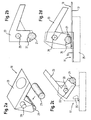
- FIGS. 2a-2d show an example of a compression device according to the invention 19, which comprises a manually operable pressing lever 23, the by means of two journals 29 pivotable on a cable carrier 11 can be stored. While a lever arm as the operating section is formed, this is the contact carriers to be contacted co-acting free ends of the other lever arm yielding formed by an example here as a cylindrical at the free end Pressing element illustrated pressing pad 21 is attached.
- the Pressing element 21 is for this purpose in a corresponding recess 31 of the pressing lever 23 used (Fig. 2b).
- Fig. 2c and 2d is formed for mounting the pressing lever 23
- Line carrier 11 indicated by dashed lines.
- the management carrier 11 is provided with fork-like bearing receptacles 33, in which the Press lever 23 can be inserted with its bearing pin 29. Further is the cable carrier 11 with an end stop 35 for the in provided the groove-like support bearings supporting lever 23.
- Fig. 2d shows in particular that in the defined by the end stop 35 End position of the pressing lever 23 a the centers of the Pivot axis defining bearing pin 29 on the one hand and the cylindrical Pressing element 21 on the other hand connecting straight line obliquely to the plane defined by the conductor supports 11, 13, in such a way that that the pressing member 21 seen in the pivoting direction in front of a vertical projection of the pivot axis is located.
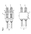
- FIG. 3 shows an example of a press-contacting of a plurality of FPC conductor carriers 13 on a single MID conductor carrier 11. This is for each FPC 13 provides a press lever 23 pivotally mounted on the MID 11, as described above.
- the inventive Pressing device thus comprises a plurality of independently usable Presstitle réelles Symposiumen.
- FIG. 4 shows an example of an application of the invention, in which the combination of one MID conductor carrier 11 and several - here two - pressing levers 23 as a distributor / connector unit between a Harness 39 and two FPC bus bars 13 are used.
- a cliplock box Unit can e.g. a roof / door, left / right or front / rear distribution will be realized.
- the invention is not limited to the MID and FPC cable carriers described above 11, 13 limited. It can, for example, also called EFC cable carriers are used. Basically you can arbitrarily configured conductor carrier in accordance with the invention by means of a pressing device are pressed against each other to an electric To make press-contact between their electrical wires. The only prerequisite for this is that the management carrier or their Electric lines are basically suitable, by pressing together to form an electrical connection.
- the electrical Lines or conductor tracks can be finished by tinning, e.g. a tinning of 2-4 microns.
- the pressing member 21 is formed so that it is in a Range from -40 ° C to + 95 ° C, especially in terms of its elastic Characteristics temperature resistant.
- the pressing element 21, with its Dimensions and its shape changeability the length of the contact zone between the electrical leads to be contacted at least significantly influenced, may e.g. from a permanently elastic Teflon roller be formed.
- the starting material may be in the form of a cable product be present elastomer, are cut off from the pressing elements 21 with the desired length.
- the pressing lever 23 may be made entirely of plastic and in particular in the form of a producible by injection molding plastic part be provided.
Landscapes
- Coupling Device And Connection With Printed Circuit (AREA)
- Multi-Conductor Connections (AREA)
- Connections By Means Of Piercing Elements, Nuts, Or Screws (AREA)
- Connections Arranged To Contact A Plurality Of Conductors (AREA)
Claims (22)
- Dispositif de connexion électrique ayant au moins deux supports de lignes (11, 13) qui sont pourvus de lignes électriques (15, 17), en particulier sous la forme de pistes conductrices, et un dispositif de serrage (19) au moyen duquel on peut établir un contact électrique par serrage en pressant les supports de lignes (11, 13) l'un contre l'autre, par lequel les lignes électriques (15, 17) sont appliquées l'une contre l'autre et serrées l'une sur l'autre,
caractérisé en ce que
le premier support de lignes (13) est prévu sous la forme d'un support de commutation flexible, en particulier sous la forme d'un FPC, et l'autre support de lignes (11) présente un corps de base (25), sur lequel sont agencées des lignes électriques en technique MID, en appliquant sur le support de lignes MID (11) le dispositif de serrage (19) au moyen duquel le support de lignes FPC (13) peut être pressé pour établir le contact de serrage contre le support de lignes MID. - Dispositif de connexion selon la revendication 1,
caractérisé en ce que
le dispositif de serrage (19) est pourvu d'une fonction de limitation de la pression. - Dispositif de connexion selon la revendication 1 ou 2,
caractérisé en ce que
le dispositif de serrage (19) se présente flexible au moins sur un côté. - Dispositif de connexion selon l'une quelconque des revendications précédentes,
caractérisé en ce que
sur au moins un côté du dispositif de serrage (19), qui coopère directement avec un (13) des supports de lignes, il est prévu un coussin de serrage (21) déformable en pressant les supports de lignes (11, 13) l'un contre l'autre. - Dispositif de connexion selon la revendication 4,
caractérisé en ce que
le coussin de serrage (21) est déformable élastiquement. - Dispositif de connexion selon la revendication 4 ou 5,
caractérisé en ce que
le coussin de serrage (21) comprend au moins un élément de serrage constitué d'un élastomère. - Dispositif de connexion selon l'une quelconque des revendications précédentes,
caractérisé en ce que
le dispositif de serrage (19) se présente sous la forme d'une pièce séparée ou d'un ensemble de pièces séparé qui peut être monté en particulier de manière amovible sur au moins un (11) des supports de lignes. - Dispositif de connexion selon l'une quelconque des revendications précédentes,
caractérisé en ce que
le dispositif de serrage (19) est monté, à l'état appliqué sur le premier support de lignes (11), de manière à pouvoir se déplacer par rapport au support de lignes (11) et peut être déplacé entre une position ouverte pour recevoir l'autre support de lignes (13) et une position fermée, dans laquelle les supports de lignes (11, 13) sont pressés l'un contre l'autre et les lignes électriques (15, 17) sont serrées l'une sur l'autre. - Dispositif de connexion selon l'une quelconque des revendications précédentes,
caractérisé en ce que
le dispositif de serrage (19) comprend au moins un levier de serrage (23) monté à pivotement sur au moins l'un des supports de lignes (11). - Dispositif de connexion selon l'une quelconque des revendications précédentes,
caractérisé en ce que
le dispositif de serrage (19) est conformé autobloquant. - Dispositif de connexion selon l'une quelconque des revendications précédentes,
caractérisé en ce que
le dispositif de serrage (19) est actionnable manuellement. - Dispositif de connexion selon l'une quelconque des revendications précédentes,
caractérisé en ce que
le premier support de lignes (11) présente une zone réceptrice (27) ajustée à l'autre support de lignes (13) et au moyen de laquelle les supports de lignes (11, 13) peuvent être alignés pour préparer le contact par serrage avec leurs lignes électriques (15, 17) l'un par rapport à l'autre. - Dispositif de connexion selon la revendication 12,
caractérisé en ce que
le dispositif de serrage (19) peut être monté sur le support de lignes (11) présentant la zone réceptrice (27). - Connecteur électrique serré avec un support de lignes (11), qui est pourvu de lignes électriques (15), en particulier sous la forme de pistes conductrices, et un dispositif de serrage (19) qui peut être monté en particulier de manière amovible sur le support de lignes (11), dispositif de compression au moyen duquel on peut, en pressant l'un contre l'autre le support de lignes (11) et un autre support de lignes (13) pourvu de lignes électriques (17), établir un contact électrique par serrage, par lequel les lignes électriques (15, 17) sont appliquées l'une contre l'autre et serrées l'une sur l'autre,
caractérisé en ce que
l'autre support de lignes (13) se présente sous la forme d'un support de commutation flexible, en particulier sous la forme d'un FPC, et le support de lignes (11), sur lequel on peut appliquer le dispositif de serrage (19), présente un corps de base (25) sur lequel sont appliquées des lignes électriques en technique MID. - Connecteur électrique serré selon la revendication 14,
caractérisé en ce que
le dispositif de serrage (19) est conformé selon l'une quelconque des revendications 2 à 11. - Connecteur électrique serré selon la revendication 14 ou 15,
caractérisé en ce que
le support de lignes, sur lequel le dispositif de serrage peut être appliqué, est conformé selon la revendication 12. - Dispositif de serrage pour un dispositif de connexion ou un connecteur serré selon l'une quelconque des revendications précédentes pour établir un contact électrique par serrage, dans lequel le dispositif de serrage (19) peut être appliqué de manière mobile sur un des supports de lignes et est pourvu d'une fonction de limitation de la pression.
- Dispositif de serrage selon la revendication 17,
caractérisé en ce que
le dispositif est conformé selon l'une quelconque des revendications 3 à 11. - Procédé pour établir une connexion électrique entre au moins deux supports de lignes (11, 13) pourvus de lignes électriques (15, 17), en particulier la sous forme de pistes conductrices, dans lequel est établi, au moyen d'un dispositif de serrage (19), en pressant les supports de lignes (11, 13) l'un contre l'autre, un contact électrique par serrage, par lequel les lignes électriques (15, 17) des supports de lignes (11, 13) sont appliquées l'une contre l'autre et sont serrées l'une sur l'autre,
caractérisé en ce que
le premier support de lignes (13) est prévu sous la forme d'un support de commutation flexible, en particulier sous la forme d'un FPC, et en ce que l'autre support de lignes (11) présente un corps de base (25) sur lequel sont appliquées des lignes électriques en technique MID, en appliquant sur le support de lignes MID (11) le dispositif de serrage (19) au moyen duquel le support de lignes FPC (13) peut être pressé contre le support de lignes MID (11) pour établir le contact par serrage. - Procédé selon la revendication 19,
caractérisé en ce que
au moins un (13) des supports de lignes est directement sollicité par le dispositif de serrage (19). - Procédé selon la revendication 20,
caractérisé en ce que
le support de lignes (13) est sollicité par un côté du dispositif de serrage (19) conformé de manière flexible, en particulier pourvu d'au moins un coussin de serrage déformable (21). - Procédé selon l'une quelconque des revendications 19 à 21,
caractérisé en ce que
pour préparer le contact par serrage, les supports de lignes (11, 13) sont alignés l'un sur l'autre avec leurs lignes électriques (15, 17), au moyen d'une zone réceptrice (27) formée sur le premier support de lignes (11) et ajustée à l'autre support de lignes (13).
Priority Applications (3)
| Application Number | Priority Date | Filing Date | Title |
|---|---|---|---|
| DE502004000156T DE502004000156D1 (de) | 2004-04-01 | 2004-04-01 | Elektrische Anschlussvorrichtung |
| AT04007942T ATE311673T1 (de) | 2004-04-01 | 2004-04-01 | Elektrische anschlussvorrichtung |
| EP04007942A EP1583177B1 (fr) | 2004-04-01 | 2004-04-01 | Dispositif de connexion électrique |
Applications Claiming Priority (1)
| Application Number | Priority Date | Filing Date | Title |
|---|---|---|---|
| EP04007942A EP1583177B1 (fr) | 2004-04-01 | 2004-04-01 | Dispositif de connexion électrique |
Publications (2)
| Publication Number | Publication Date |
|---|---|
| EP1583177A1 EP1583177A1 (fr) | 2005-10-05 |
| EP1583177B1 true EP1583177B1 (fr) | 2005-11-30 |
Family
ID=34878234
Family Applications (1)
| Application Number | Title | Priority Date | Filing Date |
|---|---|---|---|
| EP04007942A Expired - Lifetime EP1583177B1 (fr) | 2004-04-01 | 2004-04-01 | Dispositif de connexion électrique |
Country Status (3)
| Country | Link |
|---|---|
| EP (1) | EP1583177B1 (fr) |
| AT (1) | ATE311673T1 (fr) |
| DE (1) | DE502004000156D1 (fr) |
Family Cites Families (3)
| Publication number | Priority date | Publication date | Assignee | Title |
|---|---|---|---|---|
| US4610495A (en) * | 1985-03-07 | 1986-09-09 | Rogers Corporation | Solderless connector apparatus and method of making the same |
| US4975068A (en) * | 1989-12-04 | 1990-12-04 | International Business Machines | Flexible cable connector |
| DE10121307C1 (de) * | 2001-05-02 | 2002-12-05 | Framatome Connectors Int | Verbindungssystem für Flex-Flachbandkabel mit Exzenter |
-
2004
- 2004-04-01 EP EP04007942A patent/EP1583177B1/fr not_active Expired - Lifetime
- 2004-04-01 DE DE502004000156T patent/DE502004000156D1/de not_active Expired - Lifetime
- 2004-04-01 AT AT04007942T patent/ATE311673T1/de not_active IP Right Cessation
Also Published As
| Publication number | Publication date |
|---|---|
| ATE311673T1 (de) | 2005-12-15 |
| DE502004000156D1 (de) | 2006-01-05 |
| EP1583177A1 (fr) | 2005-10-05 |
Similar Documents
| Publication | Publication Date | Title |
|---|---|---|
| EP1559175B1 (fr) | Ensemble connecteur dispose entre un cable plat flexible et un composant | |
| EP1966855B1 (fr) | Connexion enfichable d'etablissement de contact | |
| EP3025396B1 (fr) | Terminal permettant la mise en contact électrique d'un conducteur électrique | |
| DE60218961T2 (de) | Einpress-Sammelschiene für Leistungsversorgung | |
| DE102006013796B4 (de) | Verfahren zum Abschirmen und Kontaktieren eines Flachleitungskörpers und Kabelbaum mit einem solchen Flachleitungskörper | |
| DE19527751A1 (de) | Verbinder für ein Kabel | |
| EP1559171A2 (fr) | Connecteur destine au raccordement de deux conducteurs plats et systeme connecteur associe | |
| DE202022002389U1 (de) | Direktsteckfederkraftmodul | |
| DE102016124172A1 (de) | Steckverbinder zur kraftlosen Kontaktierung auf einer Leiterkarte | |
| DE4412968C2 (de) | Elektrischer Verbindungskasten | |
| EP2545614B1 (fr) | Connecteur | |
| WO2009135733A1 (fr) | Mise en contact de réglettes de contacts à couteaux par le biais de cartes de circuit imprimé intermédiaires | |
| DE19832011A1 (de) | Flachbandleitung mit einem zum lösbaren Verbinden vorgesehenen Anschlußbereich | |
| DE202008014542U1 (de) | Steckverbinder für Schaltungsplatinen | |
| EP3076188B1 (fr) | Contacteur de test, procede et utilisation | |
| DE69401046T2 (de) | Elektrischer Kleinmotor mit Anschlusseinrichtung | |
| DE102004049575B4 (de) | Elektrisches Anschlusselement und Verfahren zum Anschließen eines Leiterkabels | |
| DE602004008094T2 (de) | Elektrischer verbinder für einen flexiblen flachleiter und schalteinrichtung | |
| EP1269579B1 (fr) | Connecteur a fiches pour conducteurs a bande plate | |
| EP1583177B1 (fr) | Dispositif de connexion électrique | |
| DE19948037B4 (de) | Elektrisches Steckverbindungselement und -system | |
| DE102008054950B4 (de) | Kontaktierungsvorrichtung | |
| DE102015121832B4 (de) | Steckverbinder zur elektrischen Direktkontaktierung und Steckverbindung | |
| DE102008051286B4 (de) | Kontaktiereinrichtung für Leiterplatten | |
| EP3700018B1 (fr) | Dispositif de contact direct pour cartes de circuit imprimé permettant de produire un contact électrique, ainsi que carte de circuit imprimé et appareil électrique |
Legal Events
| Date | Code | Title | Description |
|---|---|---|---|
| GRAP | Despatch of communication of intention to grant a patent |
Free format text: ORIGINAL CODE: EPIDOSNIGR1 |
|
| PUAI | Public reference made under article 153(3) epc to a published international application that has entered the european phase |
Free format text: ORIGINAL CODE: 0009012 |
|
| GRAS | Grant fee paid |
Free format text: ORIGINAL CODE: EPIDOSNIGR3 |
|
| 17P | Request for examination filed |
Effective date: 20041022 |
|
| AK | Designated contracting states |
Kind code of ref document: A1 Designated state(s): AT BE BG CH CY CZ DE DK EE ES FI FR GB GR HU IE IT LI LU MC NL PL PT RO SE SI SK TR |
|
| AX | Request for extension of the european patent |
Extension state: AL HR LT LV MK |
|
| GRAA | (expected) grant |
Free format text: ORIGINAL CODE: 0009210 |
|
| AK | Designated contracting states |
Kind code of ref document: B1 Designated state(s): AT BE BG CH CY CZ DE DK EE ES FI FR GB GR HU IE IT LI LU MC NL PL PT RO SE SI SK TR |
|
| PG25 | Lapsed in a contracting state [announced via postgrant information from national office to epo] |
Ref country code: SI Free format text: LAPSE BECAUSE OF FAILURE TO SUBMIT A TRANSLATION OF THE DESCRIPTION OR TO PAY THE FEE WITHIN THE PRESCRIBED TIME-LIMIT Effective date: 20051130 Ref country code: PL Free format text: LAPSE BECAUSE OF FAILURE TO SUBMIT A TRANSLATION OF THE DESCRIPTION OR TO PAY THE FEE WITHIN THE PRESCRIBED TIME-LIMIT Effective date: 20051130 Ref country code: RO Free format text: LAPSE BECAUSE OF FAILURE TO SUBMIT A TRANSLATION OF THE DESCRIPTION OR TO PAY THE FEE WITHIN THE PRESCRIBED TIME-LIMIT Effective date: 20051130 Ref country code: CZ Free format text: LAPSE BECAUSE OF FAILURE TO SUBMIT A TRANSLATION OF THE DESCRIPTION OR TO PAY THE FEE WITHIN THE PRESCRIBED TIME-LIMIT Effective date: 20051130 Ref country code: NL Free format text: LAPSE BECAUSE OF FAILURE TO SUBMIT A TRANSLATION OF THE DESCRIPTION OR TO PAY THE FEE WITHIN THE PRESCRIBED TIME-LIMIT Effective date: 20051130 Ref country code: SK Free format text: LAPSE BECAUSE OF FAILURE TO SUBMIT A TRANSLATION OF THE DESCRIPTION OR TO PAY THE FEE WITHIN THE PRESCRIBED TIME-LIMIT Effective date: 20051130 Ref country code: IE Free format text: LAPSE BECAUSE OF FAILURE TO SUBMIT A TRANSLATION OF THE DESCRIPTION OR TO PAY THE FEE WITHIN THE PRESCRIBED TIME-LIMIT Effective date: 20051130 Ref country code: GB Free format text: LAPSE BECAUSE OF FAILURE TO SUBMIT A TRANSLATION OF THE DESCRIPTION OR TO PAY THE FEE WITHIN THE PRESCRIBED TIME-LIMIT Effective date: 20051130 Ref country code: FI Free format text: LAPSE BECAUSE OF FAILURE TO SUBMIT A TRANSLATION OF THE DESCRIPTION OR TO PAY THE FEE WITHIN THE PRESCRIBED TIME-LIMIT Effective date: 20051130 |
|
| REG | Reference to a national code |
Ref country code: CH Ref legal event code: EP Ref country code: GB Ref legal event code: FG4D Free format text: NOT ENGLISH |
|
| REG | Reference to a national code |
Ref country code: IE Ref legal event code: FG4D Free format text: LANGUAGE OF EP DOCUMENT: GERMAN |
|
| REF | Corresponds to: |
Ref document number: 502004000156 Country of ref document: DE Date of ref document: 20060105 Kind code of ref document: P |
|
| PG25 | Lapsed in a contracting state [announced via postgrant information from national office to epo] |
Ref country code: BG Free format text: LAPSE BECAUSE OF FAILURE TO SUBMIT A TRANSLATION OF THE DESCRIPTION OR TO PAY THE FEE WITHIN THE PRESCRIBED TIME-LIMIT Effective date: 20060228 Ref country code: SE Free format text: LAPSE BECAUSE OF FAILURE TO SUBMIT A TRANSLATION OF THE DESCRIPTION OR TO PAY THE FEE WITHIN THE PRESCRIBED TIME-LIMIT Effective date: 20060228 Ref country code: GR Free format text: LAPSE BECAUSE OF FAILURE TO SUBMIT A TRANSLATION OF THE DESCRIPTION OR TO PAY THE FEE WITHIN THE PRESCRIBED TIME-LIMIT Effective date: 20060228 Ref country code: DK Free format text: LAPSE BECAUSE OF FAILURE TO SUBMIT A TRANSLATION OF THE DESCRIPTION OR TO PAY THE FEE WITHIN THE PRESCRIBED TIME-LIMIT Effective date: 20060228 |
|
| PG25 | Lapsed in a contracting state [announced via postgrant information from national office to epo] |
Ref country code: ES Free format text: LAPSE BECAUSE OF FAILURE TO SUBMIT A TRANSLATION OF THE DESCRIPTION OR TO PAY THE FEE WITHIN THE PRESCRIBED TIME-LIMIT Effective date: 20060313 |
|
| PG25 | Lapsed in a contracting state [announced via postgrant information from national office to epo] |
Ref country code: AT Free format text: LAPSE BECAUSE OF NON-PAYMENT OF DUE FEES Effective date: 20060401 |
|
| PG25 | Lapsed in a contracting state [announced via postgrant information from national office to epo] |
Ref country code: MC Free format text: LAPSE BECAUSE OF NON-PAYMENT OF DUE FEES Effective date: 20060430 Ref country code: BE Free format text: LAPSE BECAUSE OF NON-PAYMENT OF DUE FEES Effective date: 20060430 |
|
| PG25 | Lapsed in a contracting state [announced via postgrant information from national office to epo] |
Ref country code: PT Free format text: LAPSE BECAUSE OF FAILURE TO SUBMIT A TRANSLATION OF THE DESCRIPTION OR TO PAY THE FEE WITHIN THE PRESCRIBED TIME-LIMIT Effective date: 20060502 |
|
| NLV1 | Nl: lapsed or annulled due to failure to fulfill the requirements of art. 29p and 29m of the patents act | ||
| PG25 | Lapsed in a contracting state [announced via postgrant information from national office to epo] |
Ref country code: HU Free format text: LAPSE BECAUSE OF FAILURE TO SUBMIT A TRANSLATION OF THE DESCRIPTION OR TO PAY THE FEE WITHIN THE PRESCRIBED TIME-LIMIT Effective date: 20060601 |
|
| AKX | Designation fees paid |
Designated state(s): AT BE BG CH CY CZ DE DK EE ES FI FR GB GR HU IE IT LI LU MC NL PL PT RO SE SI SK TR |
|
| GBV | Gb: ep patent (uk) treated as always having been void in accordance with gb section 77(7)/1977 [no translation filed] |
Effective date: 20051130 |
|
| REG | Reference to a national code |
Ref country code: IE Ref legal event code: FD4D |
|
| ET | Fr: translation filed | ||
| PLBE | No opposition filed within time limit |
Free format text: ORIGINAL CODE: 0009261 |
|
| STAA | Information on the status of an ep patent application or granted ep patent |
Free format text: STATUS: NO OPPOSITION FILED WITHIN TIME LIMIT |
|
| 26N | No opposition filed |
Effective date: 20060831 |
|
| BERE | Be: lapsed |
Owner name: DELPHI TECHNOLOGIES, INC. Effective date: 20060430 |
|
| PG25 | Lapsed in a contracting state [announced via postgrant information from national office to epo] |
Ref country code: EE Free format text: LAPSE BECAUSE OF FAILURE TO SUBMIT A TRANSLATION OF THE DESCRIPTION OR TO PAY THE FEE WITHIN THE PRESCRIBED TIME-LIMIT Effective date: 20051130 |
|
| PG25 | Lapsed in a contracting state [announced via postgrant information from national office to epo] |
Ref country code: LU Free format text: LAPSE BECAUSE OF NON-PAYMENT OF DUE FEES Effective date: 20060401 Ref country code: TR Free format text: LAPSE BECAUSE OF FAILURE TO SUBMIT A TRANSLATION OF THE DESCRIPTION OR TO PAY THE FEE WITHIN THE PRESCRIBED TIME-LIMIT Effective date: 20051130 |
|
| PG25 | Lapsed in a contracting state [announced via postgrant information from national office to epo] |
Ref country code: CY Free format text: LAPSE BECAUSE OF FAILURE TO SUBMIT A TRANSLATION OF THE DESCRIPTION OR TO PAY THE FEE WITHIN THE PRESCRIBED TIME-LIMIT Effective date: 20051130 |
|
| REG | Reference to a national code |
Ref country code: CH Ref legal event code: PL |
|
| PG25 | Lapsed in a contracting state [announced via postgrant information from national office to epo] |
Ref country code: LI Free format text: LAPSE BECAUSE OF NON-PAYMENT OF DUE FEES Effective date: 20080430 Ref country code: CH Free format text: LAPSE BECAUSE OF NON-PAYMENT OF DUE FEES Effective date: 20080430 |
|
| PGFP | Annual fee paid to national office [announced via postgrant information from national office to epo] |
Ref country code: FR Payment date: 20100521 Year of fee payment: 7 |
|
| PGFP | Annual fee paid to national office [announced via postgrant information from national office to epo] |
Ref country code: DE Payment date: 20100430 Year of fee payment: 7 Ref country code: IT Payment date: 20100416 Year of fee payment: 7 |
|
| REG | Reference to a national code |
Ref country code: FR Ref legal event code: ST Effective date: 20111230 |
|
| PG25 | Lapsed in a contracting state [announced via postgrant information from national office to epo] |
Ref country code: DE Free format text: LAPSE BECAUSE OF NON-PAYMENT OF DUE FEES Effective date: 20111101 Ref country code: FR Free format text: LAPSE BECAUSE OF NON-PAYMENT OF DUE FEES Effective date: 20110502 |
|
| PG25 | Lapsed in a contracting state [announced via postgrant information from national office to epo] |
Ref country code: IT Free format text: LAPSE BECAUSE OF NON-PAYMENT OF DUE FEES Effective date: 20110401 |
|
| REG | Reference to a national code |
Ref country code: DE Ref legal event code: R119 Ref document number: 502004000156 Country of ref document: DE Effective date: 20111101 |
|
| P01 | Opt-out of the competence of the unified patent court (upc) registered |
Effective date: 20230425 |