EP1583902B1 - Soupape et procedes associes permettant de reduire la pression fluidique et de produire de l electricite - Google Patents
Soupape et procedes associes permettant de reduire la pression fluidique et de produire de l electricite Download PDFInfo
- Publication number
- EP1583902B1 EP1583902B1 EP03814881.3A EP03814881A EP1583902B1 EP 1583902 B1 EP1583902 B1 EP 1583902B1 EP 03814881 A EP03814881 A EP 03814881A EP 1583902 B1 EP1583902 B1 EP 1583902B1
- Authority
- EP
- European Patent Office
- Prior art keywords
- flow
- fluid
- valve
- pressure
- turbine
- Prior art date
- Legal status (The legal status is an assumption and is not a legal conclusion. Google has not performed a legal analysis and makes no representation as to the accuracy of the status listed.)
- Expired - Lifetime
Links
- 239000012530 fluid Substances 0.000 title claims description 195
- 239000007788 liquid Substances 0.000 claims description 14
- 230000007423 decrease Effects 0.000 claims description 9
- XLYOFNOQVPJJNP-UHFFFAOYSA-N water Substances O XLYOFNOQVPJJNP-UHFFFAOYSA-N 0.000 description 9
- 230000005540 biological transmission Effects 0.000 description 6
- 230000009467 reduction Effects 0.000 description 6
- 230000001105 regulatory effect Effects 0.000 description 6
- 208000032370 Secondary transmission Diseases 0.000 description 4
- 230000005611 electricity Effects 0.000 description 3
- 238000010248 power generation Methods 0.000 description 3
- 230000003247 decreasing effect Effects 0.000 description 2
- 238000002347 injection Methods 0.000 description 2
- 239000007924 injection Substances 0.000 description 2
- 238000007599 discharging Methods 0.000 description 1
- 230000005484 gravity Effects 0.000 description 1
- 230000001902 propagating effect Effects 0.000 description 1
- 230000035945 sensitivity Effects 0.000 description 1
- 239000008400 supply water Substances 0.000 description 1
Images

Classifications
-
- E—FIXED CONSTRUCTIONS
- E03—WATER SUPPLY; SEWERAGE
- E03B—INSTALLATIONS OR METHODS FOR OBTAINING, COLLECTING, OR DISTRIBUTING WATER
- E03B7/00—Water main or service pipe systems
- E03B7/07—Arrangement of devices, e.g. filters, flow controls, measuring devices, siphons or valves, in the pipe systems
- E03B7/075—Arrangement of devices for control of pressure or flow rate
-
- F—MECHANICAL ENGINEERING; LIGHTING; HEATING; WEAPONS; BLASTING
- F03—MACHINES OR ENGINES FOR LIQUIDS; WIND, SPRING, OR WEIGHT MOTORS; PRODUCING MECHANICAL POWER OR A REACTIVE PROPULSIVE THRUST, NOT OTHERWISE PROVIDED FOR
- F03B—MACHINES OR ENGINES FOR LIQUIDS
- F03B13/00—Adaptations of machines or engines for special use; Combinations of machines or engines with driving or driven apparatus; Power stations or aggregates
-
- F—MECHANICAL ENGINEERING; LIGHTING; HEATING; WEAPONS; BLASTING
- F05—INDEXING SCHEMES RELATING TO ENGINES OR PUMPS IN VARIOUS SUBCLASSES OF CLASSES F01-F04
- F05B—INDEXING SCHEME RELATING TO WIND, SPRING, WEIGHT, INERTIA OR LIKE MOTORS, TO MACHINES OR ENGINES FOR LIQUIDS COVERED BY SUBCLASSES F03B, F03D AND F03G
- F05B2220/00—Application
- F05B2220/60—Application making use of surplus or waste energy
- F05B2220/602—Application making use of surplus or waste energy with energy recovery turbines
-
- Y—GENERAL TAGGING OF NEW TECHNOLOGICAL DEVELOPMENTS; GENERAL TAGGING OF CROSS-SECTIONAL TECHNOLOGIES SPANNING OVER SEVERAL SECTIONS OF THE IPC; TECHNICAL SUBJECTS COVERED BY FORMER USPC CROSS-REFERENCE ART COLLECTIONS [XRACs] AND DIGESTS
- Y02—TECHNOLOGIES OR APPLICATIONS FOR MITIGATION OR ADAPTATION AGAINST CLIMATE CHANGE
- Y02B—CLIMATE CHANGE MITIGATION TECHNOLOGIES RELATED TO BUILDINGS, e.g. HOUSING, HOUSE APPLIANCES OR RELATED END-USER APPLICATIONS
- Y02B10/00—Integration of renewable energy sources in buildings
- Y02B10/50—Hydropower in dwellings
Definitions
- Fluid distribution networks are used in a variety of applications to distribute fluid from a central reservoir to one or more remote locations where the fluid is available for use.
- one or more main transmission lines convey the fluid from the reservoir to one or more branch transmission lines that, in turn, convey the fluid to a respective one or more remote locations.
- the fluid-distribution network is designed to distribute more fluid than all the remote locations can simultaneously consume.
- the fluid distribution network is designed to provide the maximum amount of fluid at a pressure significantly higher than the highest design pressure of all the remote locations. Consequently, fluid-distribution networks typically include pressure-reducing valves to reduce the pressure and flow rate of the fluid before the fluid reaches the remote locations.
- a typical water-distribution system used by a city to supply water for commercial and residential use includes one or more main water lines that convey water from a local reservoir or pump station to zones within the city.
- Each zone typically includes a secondary water line that conveys the water from the main lines to neighborhoods within the zone.
- each neighborhood typically includes a consumer distribution line that conveys the water from the secondary lines to the individual consumers within the neighborhood.
- the design pressure of the fluid received by the individual consumer is typically 2.7577 bars (40 pounds per square inch (psi)) while the design pressure of the fluid in the main water lines is typically 20.6843 bars (300 psi). Consequently, pressure reducing valves are typically placed at the junctions of the main and secondary water lines and at the junctions of the secondary water lines and the consumer distribution lines. Pressure reducing valves, however, may also be placed within the main, secondary or consumer distribution lines.
- FIG. 1 is a cut-away view of a conventional pressure reducing valve 10 incorporated in a typical fluid distribution network (omitted from FIG. 1 for clarity).
- the valve 10 includes an inlet portion 12 for receiving fluid having an inlet pressure, an outlet portion 14 for discharging fluid having a discharge pressure that is less than the inlet pressure, and a gate assembly 16 for regulating the amount of fluid allowed to flow from the inlet portion 12 to the outlet portion 14.
- the gate assembly 16 includes a piston 18 that can be moved relative to a piston seat 20 to increase or decrease the amount of fluid allowed to flow from the inlet portion 12 to the outlet portion 14. Even when the piston 18 is fully open, the amount of fluid allowed to flow into the outlet portion 14 is less than the amount of fluid that would normally flow through a transmission line without the valve 10.
- valve 10 reduces the pressure of the fluid flowing out of the outlet portion 14 by reducing the amount of fluid flowing through the valve 10.
- the inlet pressure causes the flow velocity of the fluid flowing between the piston 18 and the piston seat 20 to increase with respect to the velocity of the fluid into the inlet portion 12 .
- the flow velocity, and thus the flow energy of the fluid discharged from the outlet 14 is then reduced by turbulence that is generated within the flow as the fluid flows away from the valve 10, by changes in the direction of the flow as the fluid proceeds through the network, and by friction between the interior walls of the transmission lines and the fluid.
- U.S 4142367 teaches how to use the energy released from the flow for generating power by using a fluid motor including a rotatable shaft.
- a valve for reducing fluid pressure uses the energy released from the fluid to generate power.
- the valve includes a housing, a turbine disposed within the housing, a valve out, a fluid reservoir and a flow control device operable to generate a turbine inlet flow having a flow velocity from an inlet flow having a fluid pressure.
- the turbine receives the turbine inlet flow, which rotates the turbine to generate power.
- the fluid reservoir collects the turbine inlet flow after the flow is discharged from the turbine and generates a valve discharge flow having a fluid pressure that is less than the fluid pressure of the in let flow.
- the valve outlet discharges the valve discharge flow.
- the pressure removed from the inlet flow releases energy that is used to generate power.
- the power generated by the turbine can be independent of the pressure of the fluid discharged from the valve. Consequently, the valve can provide a desired reduction in fluid pressure and/or flow rate while the turbine generates power. To convert this power to electricity, one can drive an electrical generator with the turbine.
- FIG. 1 is a cut-away view of a conventional valve for reducing fluid pressure.
- FIG. 2 is a schematic view of a valve for reducing fluid pressure and generating power, according to an embodiment of the invention.
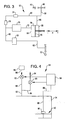
- FIG. 3 is a schematic view of a flow-control circuit incorporated in the valve of FIG. 2 according to an embodiment of the invention.
- FIG. 4 is a schematic view of a pressure control circuit incorporated in the valve of FIG. 2 according to an embodiment of the invention.
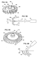
- FIG. 5A is a perspective view of a turbine that includes buckets and may be incorporated in the valve of FIG. 2 according to an embodiment of the invention.
- FIG. 5B is a view of a turbine inlet flow striking a bucket of the turbine of FIG. 5A to generate power according to an embodiment of the invention.
- FIG. 6A is a perspective view of a turbine that includes vanes and may be incorporated in the valve of FIG. 2 according to another embodiment of the invention.
- FIG. 6B is a view of a turbine inlet flow striking more than one vane of the turbine of FIG. 6A to generate power according to an embodiment of the invention.
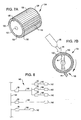
- FIG. 7A is a perspective view of another turbine that may be incorporated in the valve of FIG. 2 according to yet another embodiment of the invention.
- FIG. 7B is a view of a turbine inlet flow striking the turbine of FIG. 7A to generate power according to an embodiment of the invention.
- FIG. 8 is a schematic view of a fluid distribution network that incorporates the valve of FIG. 2 according to an embodiment of the invention.
- FIG. 2 is a schematic view of a valve 30, according to an embodiment of the invention, for reducing fluid pressure in a fluid distribution network (not shown) and generating power from the pressure removed.
- the valve 30 generates a valve discharge flow 32 having a pressure and/or flow rate that can be independent of the amount of power generated by the valve 30. That is, the amount of power generated by the valve 30 does not affect the amount of fluid pressure the valve 30 removes from the fluid in the fluid distribution network.
- the valve 30 generates a consistent valve discharge flow 32 whether the valve 30 generates power or not.
- the valve 30 includes a housing 34, a flow-control device 36 mounted to the housing 34, and a turbine 38 and a fluid reservoir 40 each disposed in the housing 34.
- the flow-control device 36 converts fluid pressure in the inlet flow 42 into flow velocity in a turbine inlet flow 44 by reducing the cross-sectional area of the inlet flow 42 through which fluid can flow relative to the cross-sectional area of the inlet pipe 46 that is coupled to the valve 30.
- the flow-control device 36 restricts the amount of fluid flowing through the valve 30 and generates a turbine inlet flow 44 having a higher ratio of flow velocity to fluid pressure than the inlet flow 42 has.
- the turbine 38 absorbs kinetic energy from the turbine inlet flow 44 and rotates a shaft 48 that can be coupled to any desired device, such as a conventional generator to generate electrical power.
- the fluid reservoir 40 collects the flow of fluid discharged from the turbine and uses the mass of the discharged fluid 50 in the reservoir to generate fluid pressure in the valve discharge flow 32.
- the valve 30 generates a valve discharge flow 32 having a fluid pressure less than the fluid pressure in the inlet flow 42 by restricting the amount of fluid allowed to flow through the valve 30.
- the valve 30 generates power by converting fluid pressure in the inlet flow 42 into flow velocity in the turbine inlet flow 44 and using the flow 44 to rotate the turbine 38.
- the valve 30 may also include a flow-control circuit 52 (discussed in greater detail in conjunction with FIG. 3 ) for regulating the fluid pressure and/or flow rate of the valve-discharge flow 32.
- the fluid-control circuit 52 senses the fluid pressure in the flow 32 and uses the fluid pressure in the inlet flow 42 to open and close the flow control device 36. When the fluid pressure in the flow 32 falls below a predetermined value, the fluid pressure in the inlet flow 42 partially or fully opens the flow control device 36. Conversely, when the fluid pressure in the flow 32 rises above a predetermined value, the fluid pressure in the inlet flow 42 partially or fully closes the flow control device 36.
- the flow control circuit 52 regulates the amount of fluid flowing through the valve 30 using negative feedback.
- the valve 30 may also include a pressure-control circuit 54 (discussed in greater detail in conjunction with FIG. 4 ) for regulating gas pressure inside the housing 34 of the valve 30.
- a pressure-control circuit 54 for regulating gas pressure inside the housing 34 of the valve 30.
- the pressure-control circuit 54 senses the liquid level in the reservoir 40. When the liquid level falls below a predetermined level, the pressure-control circuit 54 injects gas into the housing 34 to increase the gas pressure inside the housing 34. When the liquid level rises above a predetermined level, the pressure-control circuit 54 removes gas from the housing 34 to decrease the gas pressure inside the housing.
- the pressure-control circuit 54 can regulate the fluid pressure and/or flow rate of the valve discharge flow 32 by regulating the gas pressure in the housing 34.
- the flow-control device 36 may also include a nozzle to generate the turbine inlet flow 44, and an impulse turbine that includes a turbine runner (discussed in greater detail in conjunction with FIGS. 5A-7B ) to absorb the kinetic energy of the turbine inlet flow 44 and rotate the shaft 48.
- the valve 30 may include a deflector 56 pivotally attached to the housing 34 for regulating the amount of power generated by the valve 30. The amount of power generated by the turbine 38 depends on where the turbine inlet flow 44 strikes the turbine 38 and the angle at which the turbine inlet flow 44 strikes the turbine. When the deflector 56 is positioned out of the path of the turbine inlet flow 44, the flow 44 strikes the turbine unimpeded.
- the deflector 56 When the deflector is positioned in the path of the turbine inlet flow 44, the deflector 56 impedes the turbine inlet flow 44 before it strikes the turbine 38.
- the deflector may deflect some or all of the turbine inlet flow 44 away from the turbine 38 and/or change the angle at which some or all of the turbine inlet flow 44 strikes the turbine 38. Consequently, the turbine 38 generates more power when the deflector 56 is positioned out of the path of the turbine inlet flow 44 than when the deflector 56 is positioned in the path of the flow 44.
- the flow-control device 36 In operation, the flow-control device 36 generates a turbine inlet flow 44 having a relatively high flow velocity and relatively low fluid pressure from the inlet flow 42 which has, a relatively low flow velocity and relatively high fluid pressure.
- the turbine inlet flow 44 may have a flow velocity of 31.896 m/s (102 feet per second (ft/s)) and a fluid pressure of 6.8948 bars (100 psi)
- the inlet flow 42 may have a flow velocity of 0.3048 m/s (1 ft/s) and fluid pressure of 13.7895 bars (200 psi).
- the turbine inlet flow 44 strikes the turbine 38 and causes the turbine to rotate. By rotating, the turbine 38 converts the kinetic energy in the turbine inlet flow 44 to rotation of the shaft 48.
- the shaft 48 may be coupled to a device such as an electrical generator that converts the rotation of the shaft 48 into electrical power.
- the fluid pressure in the inlet flow 42 is converted into flow velocity in the turbine inlet flow 44, which is used to rotate the shaft 48 to generate power.
- the turbine inlet flow 44 strikes the turbine 38, the flow 44 proceeds by gravity or other means to the fluid reservoir 40 where the spent flow is collected.
- the fluid pressure and flow rate of the valve discharge flow 32 is generated by the fluid pressure of the fluid 50 in the reservoir 40 at the valve outlet 57.
- valve 30 generates a valve discharge flow 32 having a fluid pressure that is less than the fluid pressure in the inlet flow 42 by restricting the amount of fluid that flows into the fluid reservoir 40 from the inlet flow 42.
- the valve 30 may include at least two flow-control devices 36 each coupled to the same inlet pipe 46.
- the valve 30 may include at least two flow-control devices 36 each coupled to a different inlet pipe 46.
- the valve 30 may include at least two flow-control devices 36 each generating a turbine inlet flow 44 that strikes a single turbine 38.
- the valve 30 may include at least two turbines 38 disposed in the housing 34.
- the valve 30 may include at least two reservoirs.
- the valve 30 may be coupled to at least two outlet pipes for distributing a valve discharge flow to different branches of a fluid distribution network (not shown).
- the valve 30 may generate two different valve discharge flows 32 at the same time and supply a respective one of the outlet pipes with one of the valve discharge flows.
- FIG. 3 is a schematic view of the flow-control circuit 52 incorporated in the valve 30 of FIG. 2 according to an embodiment in the invention.
- the flow-control circuit 52 substantially maintains the desired fluid pressure and/or flow rate in the valve discharge flow 32 by regulating the amount of fluid contained in the turbine inlet flow 44 ( FIG. 2 ). Consequently, when the fluid pressure in the valve discharge flow 32 changes because flow conditions in other portions of the fluid distribution network (not shown) change, the flow-control circuit 52 increases or decreases the amount of fluid flowing in the turbine inlet flow 44 to maintain the desired flow characteristics in the valve discharge flow 32. For example, if the fluid pressure in the valve discharge flow 32 increases, the flow-control circuit 52 closes the flow-control device 36 ( FIG. 2 ) to reduce or stop the flow of fluid through the valve 30. Conversely, when the fluid pressure decreases in the discharge flow 32, the flow-control circuit 52 opens the flow control device 36 to increase the flow of fluid through the valve 30.
- the flow-control circuit 52 uses the fluid pressure in the inlet flow 42 ( FIG. 2 ) to open and close the flow-control device 36.
- the flow-control circuit 52 includes a line 58 coupled to the inlet pipe 46, the line 58 distributes a portion of the inlet flow 42 having an inlet pressure to the other components of the circuit 52, and branches into two lines 60 and 62 before distributing the flow 42 to the circuit's other components.
- the flow-control circuit 52 also includes a housing 64, a diaphragm 66 coupled to the flow-control device 36 and separating the housing 64 into two chambers 68 and 70.
- the line 60 is coupled to the chamber 68 and provides a portion of the inlet flow 42 to the chamber 68.
- Line 72 couples the line 62 to the chamber 70 to provide a portion of the inlet flow 42 to the chamber 68.
- the diaphragm moves in the +X direction to close the flow-control device 36 because the area of the diaphragm exposed to the chamber 70 is greater than the area exposed to the chamber 68.
- the diaphragm moves in the -X direction to open the flow-control device 36.
- the increase and decrease of the fluid pressure in the chamber 70 is determined by a portion of the inlet flow 42 flowing through the line 62 and into the valve discharge flow 32.
- the valve discharge flow 32 has a less-than-desired fluid pressure
- fluid flows through line 62 into the flow 32 causing the fluid pressure in the chamber 70 to decrease. Consequently, the fluid pressure in the chamber 68 causes the diaphragm to move in the -X direction.
- the valve discharge flow 32 has a fluid pressure exceeding a desired fluid pressure, fluid does not flow, or flows more slowly, through the line 62. Consequently, the fluid pressure in the chamber 70 increases and thus, the diaphragm moves in the +X direction.
- the flow-control circuit 52 may include a check valve 74 to prevent the flow of fluid in the line 62 toward the inlet pipe 46, a flow restrictor 76 to reduce the amount of fluid flowing through the lines 62 and 72, a flow-rate control valve 78 to mitigate sudden pressure changes in the circuit 52, and a pressure-reducing valve 80 to reduce the fluid pressure in the line 62 before the fluid enters the valve discharge flow 32. If the fluid pressure in the valve discharge flow 32 exceeds the fluid pressure in the inlet flow 42, the increase in fluid pressure or fluid flowing in the opposite direction in the portion of the network that includes the inlet pipe 46 could damage other components in the network. Therefore, the check valve 74 may help isolate each portion of the network coupled to the valve 30.
- the flow-rate control valve 78 minimizes fluid "hammers" - sudden increases in fluid pressure - that can be generated by opening and closing the flow control device 36 quickly. Fluid hammers propagating through the fluid distribution network can damage other components of the network, and thus, minimizing them may be desirable.
- the pressure-reducing valve 80 ensures that the fluid entering the valve discharge flow 32 through the line 62 does not significantly affect the fluid pressure and/or flow rate of the valve discharge flow 32. Furthermore, the valve 80 may be used to change the pressure in the valve discharge flow 32 as desired by adjusting the output pressure of the valve 80.
- the flow-control circuit 52 uses fluid from the inlet flow 42 to open and close the flow-control device 36
- the circuit 52 may use electricity, compressed gas such as air, or other types of fluid different than the fluid distributed by the distribution network. If the flow-control circuit 52 uses electricity, compressed gas, or other types of fluid, the circuit 52 may include components designed to function with the specific medium used.
- FIG. 4 is a schematic view of the pressure-control circuit 54 of FIG. 2 according to an embodiment of the invention.
- the pressure-control circuit 54 regulates the gas pressure inside the housing 34 ( FIG. 2 ) of the valve 30 by injecting gas into or releasing gas from the housing 34 as desired.
- the housing 34 pressurized, the liquid level in the reservoir 40 required to generate a desired fluid pressure in the valve discharge flow 32 can be reduced. Consequently, the size of the valve 30 can be reduced.
- the liquid in the reservoir 40 can be used to impede the turbine 38 in FIG. 2 to help reduce the power generated by the valve 30.
- the level of the liquid in the reservoir 40 may rise to partially or wholly submerge the turbine 38.
- the pressure-control circuit 54 includes a line 82 coupled to the housing 34.
- the line 82 branches into an exhaust line 84 and an injection line 86.
- the circuit 54 also includes a source of pressurize gas 88 coupled to the injection line 86 for supplying compressed gas to the housing 34, and two valves 90 and 92 each coupled to one of the respective lines 84 and 86.
- the pressure-control circuit 54 also includes a control module 94 that opens and closes the valves 90 and 92 as required to increase, decrease, or maintain the gas pressure in the housing 34.
- the pressure-control circuit 54 also includes a float 96 that senses the level of the liquid in the reservoir 40 and a line 98 that conveys the information from the float 96 to the control module 94.
- the control module 94 When the liquid level falls below a predetermined level, the control module 94 partially or fully closes the valve 90 if the valve 90 is open and partially or fully opens the valve 92 to inject gas into the housing 34.
- the fluid pressure in the valve discharge flow 32 ( FIGS. 2 and 3 ) can be increased to the desired pressure without modifying the flow-control device 36 ( FIG. 2 ) to allow more fluid into the housing 34.
- the control module 94 partially or fully closes the valve 92 if the valve 92 is open and partially or fully opens the valve 90 to remove gas from the housing 34.
- the fluid pressure in the valve discharge flow 32 can be decreased to the desired pressure without modifying the flow-control device 36 to reduce the amount of fluid into the housing 34.
- the pressure-control circuit 54 may include a manometer or another device for sensing the liquid level instead of the float 96. Or, some of the power generated by the turbine 38 may be used to generate compressed gas in the compressed gas source 88.
- FIGS. 5A-7B illustrate different impulse turbines 38 that the valve 30 ( FIG. 2 ) may incorporate as the turbine 38 ( FIG. 2 ) according to an embodiment of the invention, and illustrate the path of the turbine inlet flow 44 ( FIG. 2 ) as the flow strikes each impulse turbine.
- FIGS. 5A, 6A and 7A are perspective views of one of the respective impulse turbines
- FIGS. 5B, 6B and 7B are corresponding views of the turbine inlet flow 44 as the flow strikes the impulse turbine shown in one of the respective FIGS. 5A, 6A and 7A .
- the type of turbine 38 ( FIG. 2 ) incorporated in the valve 30 depends on the desired size of the valve 30 and the desired flow velocity of the turbine inlet flow 44 as described below.
- each turbine discussed in the following figures is an impulse turbine, the valve 30 may incorporate a reaction turbine or another type of turbine.
- the valve 30 includes a turbine 100 that absorbs the kinetic energy from the turbine inlet flow 44 ( FIGS. 2 and 3 ) and rotates the shaft 48 ( FIG. 2 ) to generate power.
- the turbine 100 includes a disk 102 having a circumference 104, and a plurality of buckets 106 located on the circumference for deflecting the turbine inlet flow 44.
- the turbine 100 also includes a center hole 108 to mount the turbine 100 to the shaft 48.
- the turbine 100 uses the force that the turbine inlet flow 44 imparts on the bucket 106 as the bucket changes the direction of the flow 44 to rotate the turbine 100 and thus the shaft 48.
- the flow-control device 36 generates a turbine inlet flow 44 having a high flow velocity and directs the flow 44 toward the turbine 100.
- the bucket 106 splits the flow 44 into portions 109 and 110 that are each deflected back toward the flow-control device 36. Consequently, each portion 109 and 110 pushes the bucket 106 away from the flow control device 36, causing the disk 102 to rotate.
- the bucket 106 does not have to counter the force generated by diverting the flow 44 in the +Z or -Z direction.
- the portions 109 and 110 are substantially symmetrical about the bucket axis 112
- the force generated by diverting the flow of the portion 109 in the +Z direction is countered by the force generated by diverting the flow of the portion 110 in the -Z direction.
- the turbine 100 works well for high-flow velocities, but because the buckets 106 divert the turbine inlet flow 44 back toward the flow-control device 36, the flow 44 is also diverted back toward an adjacent bucket 106. Thus, when the turbine 100 rotates fast, the turbine inlet flow 44 may impede the turbine's rotation. Therefore, the rotational speed of the turbine 100 is typically limited, and the disk 102 frequently has a large diameter. Consequently, the turbine 100 may be used in large valves designed for large reductions in pressure and designed for use with power generation equipment having a designed input shaft speed that is slow to moderate.
- the valve 30 in FIG. 2 includes a turbine 114 that absorbs the kinetic energy from the turbine inlet flow 44 ( FIGS. 2 and 3 ) and rotates the shaft 48 ( FIG. 2 ) to generate power.
- the turbine 114 includes a disk 116 having a circumference 118, and a plurality of vanes 120 extending radially from the circumference 118 for diverting the turbine inlet flow 44.
- the turbine 114 also includes a center hole 122 to mount the turbine 114 to the shaft 48.
- the vanes 120 typically have a smaller profile and may be located closer to each other around the circumference 118 than the buckets 106 ( FIGS. 5A and 5B ) around the circumference 104.
- the turbine 114 may include more vanes 120 than the turbine 100 ( FIG. 5A ) includes buckets 106. Consequently, the turbine 114 may absorb the kinetic energy of the turbine inlet flow 44 more efficiently.
- the turbine 114 is similar to the turbine 100 ( FIGS. 5A and 5B ) except that the flow-control device 36 directs the turbine inlet flow 44 toward the vanes 120 at an angle.
- the turbine inlet flow 44 generates a force on the turbine 114 in the -Z direction, which the turbine 114 counters. Decreasing the amount of force in the -Z direction countered by the turbine 114 increases the efficiency of the turbine 114.
- the vanes 120 may be designed to direct the turbine inlet flow 44 at an angle that causes the flow 44 to generate a force in the +Z direction when the flow 44 leaves the vanes 120.
- the force generated by the turbine inlet flow 44 leaving a vane 120 may balance the force generated by the flow 44 as the flow 44 strikes the turbine 114.
- the turbine 114 also works well for high-flow velocities, but because the vanes 120 do not divert the turbine inlet flow 44 back toward an adjacent vane 120, the diverted flow 44 does not impede the turbine's rotation.
- the turbine 114 may operate at faster rotational speeds than the turbine 100 of FIGS. 5A and 5B , and the disk 116 may have a smaller diameter than the diameter of the disk 102 of the turbine 100. Consequently, the turbine 114 may be used in small valves designed for large reductions in pressure and designed for use with power-generation equipment having a designed input shaft speed that is high.
- the valve 30 in FIG. 2 may include a turbine 124 that absorbs the kinetic energy from the turbine inlet flow 44 ( FIGS. 2 and 3 ) and rotates the shaft 48 ( FIG. 2 ) to generate power.
- the turbine 124 includes first and second disks 126 and 128 spaced apart from each other, and a plurality of vanes 130 extending between the disks 126 and 128 for diverting the turbine inlet flow 44.
- Each disk 126 and 128 also includes a center hole 132 (only one shown) to mount the turbine 124 to the shaft 48.
- the turbine 124 is similar to the turbines 100 ( FIGS. 5A and 5B ) and 114 ( FIGS. 6A and 6B ) except the turbine inlet flow 44 strikes the turbine 124 twice to rotate the shaft 48 before the flow 44 reaches the valve's reservoir 40 ( FIGS. 2 and 4 ).
- the turbine inlet flow 44 first strikes the vanes 130 of the upper portion 134 of the turbine 124 similar to the flow 44 striking the turbine 114. Then, the turbine inlet flow 44 passes between the disks 126 and 128 and strikes the vanes 130 of the lower portion 136. Because the turbine inlet flow 44 strikes the turbine in more than one location, the turbine may efficiently absorb much of the kinetic energy of a flow 44 having a low to moderate flow velocity.
- the turbine 124 works well for low to moderate flow velocities and may be used in small valves designed for small reductions in pressure and designed for use with power generation equipment having a designed input shaft speed that is slow to moderate.
- FIG. 8 is a schematic view of a fluid distribution network 140 that incorporates the valve 30 of FIG. 2 according to an embodiment of the invention.
- the network 140 distributes fluid having a fluid pressure to remote locations 142 from a central reservoir (not shown).
- the network 140 includes a main transmission line 144 for conveying fluid having a first fluid pressure, a secondary transmission line 146 for conveying fluid having a second fluid pressure that is less than the first fluid pressure, and a distribution line 148 for conveying fluid having a third fluid pressure that is less than the second fluid pressure.
- the network 140 also includes valves 30 for reducing fluid pressure in the network 140 and generating power from the pressure removed.
- valves 30 are each coupled to the main transmission line 144 and one of the respective secondary transmission lines 144 to reduce the first fluid pressure in the main line 144 to the second fluid pressure in the secondary lines 146.
- Other valves 30 are each coupled to a secondary transmission line 146 and one of the respective distribution lines 148 to reduce the second fluid pressure in the line 146 to the third fluid pressure in the distribution line 148.
- the network 140 provides fluid having a third fluid pressure to the remote locations 142 that are coupled to the distribution line 148, and provides fluid having a second fluid pressure to the remote locations 142 that are coupled to the secondary transmission lines 146.
Landscapes
- Engineering & Computer Science (AREA)
- Public Health (AREA)
- Health & Medical Sciences (AREA)
- Life Sciences & Earth Sciences (AREA)
- Fluid Mechanics (AREA)
- Hydrology & Water Resources (AREA)
- Physics & Mathematics (AREA)
- Water Supply & Treatment (AREA)
- Chemical & Material Sciences (AREA)
- Combustion & Propulsion (AREA)
- Mechanical Engineering (AREA)
- General Engineering & Computer Science (AREA)
- Other Liquid Machine Or Engine Such As Wave Power Use (AREA)
- Control Of Turbines (AREA)
Claims (11)
- Soupape (30) pour réduire une pression de fluide et produire de l'énergie, la soupape (30) comprenant :un boîtier (34) ;un dispositif de commande d'écoulement (36) monté sur le boîtier (34) et actionnable pour produire un écoulement d'entrée de turbine (44) ayant une vitesse d'écoulement à partir d'un écoulement d'entrée (42) ayant une pression de fluide ;une turbine (38) disposée dans le boîtier (34) et actionnable pour recevoir l'écoulement d'entrée de turbine (44) et produire une rotation pour produire de l'énergie ; caractérisé en ce que la soupape comprend en outre :un réservoir de fluide (40) actionnable pour recevoir l'écoulement d'entrée de turbine (44) après que l'écoulement est évacué de la turbine (38) et actionnable pour produire un écoulement d'évacuation de soupape (32) ayant une pression de fluide inférieure à la pression de fluide de l'écoulement d'entrée (42) ; etune sortie de soupape (57) actionnable pour évacuer l'écoulement d'évacuation de soupape (32).
- Soupape (30) selon la revendication 1, dans laquelle la pression de fluide du fluide évacué est indépendante de la quantité d'énergie produite par la turbine (38).
- Soupape (30) selon la revendication 1 ou 2, dans laquelle la pression de fluide de l'écoulement d'évacuation de soupape (32) est produit par le poids du fluide contenu dans le réservoir de fluide (40).
- Soupape (30) selon l'une quelconque des revendications 1 à 3, comprenant en outre un circuit de commande d'écoulement (52) pour détecter la pression de fluide du fluide évacué à partir de la soupape (30), en comparant la pression de fluide détectée à une pression de fluide désirée et en commandant le dispositif de commande d'écoulement (36) de façon à maintenir la pression de fluide du fluide évacué à une valeur désirée.
- Soupape (30) selon la revendication 4, dans laquelle le circuit de commande d'écoulement (52) utilise l'écoulement d'entrée (42) pour commander le dispositif de commande d'écoulement (36) pour maintenir la pression de fluide du fluide évacué à la valeur désirée.
- Soupape (30) selon la revendication 4 ou 5, dans laquelle le circuit de commande d'écoulement (52) utilise l'écoulement d'entrée (42) pour commander le dispositif de commande d'écoulement (36) pour modifier l'écoulement d'entrée de turbine (44) et comprend un logement (64) et un diaphragme (66) disposé dans le logement (64) qui sépare le logement (64) en deux chambres (68, 70), dans laquelle l'écoulement d'entrée (42) met sous pression chaque chambre, et une partie de l'écoulement d'entrée (42) circule à travers le circuit de commande (52) pour réduire la pression dans l'une des chambre pour ouvrir le dispositif de commande d'écoulement (36).
- Soupape (30) selon l'une quelconque des revendications 1 à 6, comprenant en outre un circuit de commande de pression (54) actionnable pour augmenter et diminuer la pression de gaz dans le boîtier (34) et dans laquelle la pression de fluide de l'écoulement d'évacuation de soupape (32) est produit par le poids du liquide contenu dans le réservoir de fluide (40) et la pression de gaz dans le boîtier (34).
- Soupape (30) selon la revendication 7, dans laquelle le circuit de commande de pression (54) actionnable pour augmenter et diminuer la pression de gaz dans le boîtier (34) inclut un flotteur (96) actionnable pour détecter le niveau de liquide contenu dans le réservoir de fluide (40) et un module de commande (94) actionnable pour ouvrir une soupape (92) pour injecter du gaz dans le boîtier (34) et pour fermer une soupape (92) pour arrêter l'injection du gaz dans le boîtier (34).
- Réseau de distribution de fluide (140) comprenant :un premier conduit (144) actionnable pour distribuer du fluide ayant une première pression ;un second conduit (146) actionnable pour distribuer du fluide ayant une seconde pression inférieure à la première pression ; etune soupape (30) actionnable pour réduire la pression et produire de l'énergie, et comprenant :caractérisé en ce que la soupape comprend en outre :un boîtier (34) ;un dispositif de commande d'écoulement (36) monté sur le boîtier (34) et actionnable pour produire un écoulement d'entrée de turbine (44) ayant une vitesse d'écoulement à partir du fluide dans le premier conduit (144) ;une turbine (38) disposée dans le boîtier (34) et actionnable pour recevoir l'écoulement d'entrée de turbine (44) et faire tourner pour produire de l'énergie ;un réservoir de fluide (40) actionnable pour recevoir l'écoulement d'entrée de turbine (44) après que l'écoulement est évacué de la turbine (38) et actionnable pour produire un écoulement d'évacuation de soupape (32) ayant une pression de fluide inférieure à la pression de fluide de l'écoulement d'entrée (42) ; etune sortie de soupape (57) actionnable pour évacuer l'écoulement d'évacuation de soupape (32).
- Procédé de réduction de pression dans un écoulement de fluide et de production d'énergie, ce procédé comprenant :produire, au moyen d'un dispositif de commande d'écoulement (36) un écoulement d'entrée de turbine (44) ayant une vitesse d'écoulement à partir d'un écoulement d'entrée (42) à une première pression ;projeter l'écoulement d'entrée de turbine (44) vers une turbine (38) disposée dans un boîtier (34) ;dériver l'écoulement d'entrée de turbine (44) au moyen de la turbine (38) pour faire tourner la turbine (38) ;recueillir dans un réservoir de fluide (40) l'écoulement d'entrée de turbine (44) après que l'écoulement est évacué de la turbine ; etproduire un écoulement d'évacuation de soupape (32) ayant une seconde pression désirée inférieure à la première pression.
- Procédé comprenant :convertir de l'énergie à partir d'un écoulement de fluide d'entrée (42) ayant une première pression en énergie mécanique ;produire un écoulement de fluide de sortie (32) ayant une seconde pression inférieure à la première pression ;maintenir la seconde pression à un niveau désiré en ajustant l'écoulement d'entrée de fluide (42) en réponse à l'écoulement de fluide de sortie (32) ; etrégler la pression d'un gaz dans un boîtier (34) qui reçoit l'écoulement de fluide d'entrée (42) et qui fournit l'écoulement de fluide de sortie (32).
Applications Claiming Priority (3)
| Application Number | Priority Date | Filing Date | Title |
|---|---|---|---|
| US334510 | 2002-12-30 | ||
| US10/334,510 US6824347B2 (en) | 2002-12-30 | 2002-12-30 | Valve and related methods for reducing fluid pressure and generating power |
| PCT/US2003/040609 WO2004061296A1 (fr) | 2002-12-30 | 2003-12-19 | Soupape et procedes associes permettant de reduire la pression fluidique et de produire de l'electricite |
Publications (2)
| Publication Number | Publication Date |
|---|---|
| EP1583902A1 EP1583902A1 (fr) | 2005-10-12 |
| EP1583902B1 true EP1583902B1 (fr) | 2013-05-08 |
Family
ID=32655080
Family Applications (1)
| Application Number | Title | Priority Date | Filing Date |
|---|---|---|---|
| EP03814881.3A Expired - Lifetime EP1583902B1 (fr) | 2002-12-30 | 2003-12-19 | Soupape et procedes associes permettant de reduire la pression fluidique et de produire de l electricite |
Country Status (5)
| Country | Link |
|---|---|
| US (1) | US6824347B2 (fr) |
| EP (1) | EP1583902B1 (fr) |
| AU (1) | AU2003297392A1 (fr) |
| CA (1) | CA2512148C (fr) |
| WO (1) | WO2004061296A1 (fr) |
Families Citing this family (40)
| Publication number | Priority date | Publication date | Assignee | Title |
|---|---|---|---|---|
| US6824347B2 (en) | 2002-12-30 | 2004-11-30 | Michael A. Maloney | Valve and related methods for reducing fluid pressure and generating power |
| US7608935B2 (en) * | 2003-10-22 | 2009-10-27 | Scherzer Paul L | Method and system for generating electricity utilizing naturally occurring gas |
| US7807302B2 (en) * | 2004-01-27 | 2010-10-05 | Utc Power Corporation | Preventing fuel starvation of a fuel cell stack |
| US20060045733A1 (en) * | 2004-08-30 | 2006-03-02 | Hydro-Industries Tynat Ltd. | Water turbine motor with outlet buffer reservoir |
| US20060108808A1 (en) * | 2004-11-22 | 2006-05-25 | Chen Mervyn A | System and method for generating electricity using well pressures |
| GB2430981A (en) * | 2005-10-05 | 2007-04-11 | Neil Mcvarnock | Power generator |
| NO325981B1 (no) * | 2006-07-03 | 2008-08-25 | Energreen As | Apparat og framgangsmate for regulering av energipotensialet i en fluidstreng som befinner seg i et ror |
| US7392817B2 (en) * | 2006-10-12 | 2008-07-01 | Castlebridge Enterprises, Inc. | Water conservation safety shut-off valve |
| US7605490B2 (en) * | 2007-12-10 | 2009-10-20 | Simon Srybnik | Transportable hydro-electric system |
| US7466035B1 (en) | 2008-02-26 | 2008-12-16 | Simon Srybnik | Transportable hydro-electric generating system with improved water pressure enhancement feature |
| US7564144B1 (en) | 2008-11-20 | 2009-07-21 | Simon Srybnik | Transportable hydro-electric generating system with improved water pressure enhancement feature activation systems |
| US7768146B2 (en) * | 2008-03-21 | 2010-08-03 | Alfiero Balzano | Flow generator for use in connection with a utility conduit |
| EP2119907A1 (fr) * | 2008-05-13 | 2009-11-18 | Nicolae Gabriel Corbu | Chaîne de centrales hydroélectriques fonctionnant en microcascade, turbines du générateur en cascade |
| CN102959231A (zh) * | 2010-06-16 | 2013-03-06 | 利维坦能源水电有限公司 | 带有气泡的管内水力涡轮机 |
| US20120086204A1 (en) | 2010-10-11 | 2012-04-12 | Cla-Val Co. | System and method for controlled hydroelectric power generation |
| JP6012109B2 (ja) * | 2011-06-15 | 2016-10-25 | リバイアサン エナジー ハイドロエレクトリック エルティーディー. | 気泡を伴う管内ハイドロタービン |
| ES2394937B1 (es) * | 2011-06-27 | 2013-10-10 | Vicente RUIZ GOMIS | Dispositivo de control para turbinas hidráulicas |
| KR101245450B1 (ko) * | 2012-05-14 | 2013-03-19 | 박종흠 | 급배수관용 발전형 감압장치 |
| EP2664786A1 (fr) * | 2012-05-16 | 2013-11-20 | Energreen AS | Soupape de régulation de fluide |
| EP2767716A1 (fr) | 2013-02-18 | 2014-08-20 | Energreen AS | Commande de pression redondante |
| ITMO20130051A1 (it) * | 2013-02-27 | 2014-08-28 | Lorenzo Ferioli | "valvola di regolazione con recupero energetico" |
| ITCS20130005A1 (it) * | 2013-04-15 | 2014-10-16 | Corrado Chiappetta | Serbatoio energetico per produrre energia elettrica |
| EP2826989A1 (fr) | 2013-07-15 | 2015-01-21 | Energreen AS | Soupape de régulation de fluide |
| EP2899402A1 (fr) | 2014-01-22 | 2015-07-29 | Energreen AS | Commande de rotors à lobes dans un système de générateur |
| IN2014CH03918A (fr) * | 2014-08-08 | 2015-08-28 | Balaiah Mallikarjuna CHALLA | |
| WO2016042552A1 (fr) * | 2014-09-15 | 2016-03-24 | Leviathan Energy Hydroelectric Llc. | Procédés et systèmes de turbines intégrées dans des réservoirs |
| MX388760B (es) * | 2014-12-21 | 2025-03-20 | Leviathan Energy Hydroelectric Llc | Turbinas en tubo en sistemas de transferencia de temperatura. |
| EP3553305B1 (fr) * | 2017-01-23 | 2024-11-27 | Daikin Industries, Ltd. | Système de production d'énergie hydroélectrique |
| US10753235B2 (en) * | 2018-03-16 | 2020-08-25 | Uop Llc | Use of recovered power in a process |
| FR3097311B1 (fr) * | 2019-06-12 | 2021-06-25 | Technip France | Installation de production pétrolière ou gazière, procédé correspondant et procédé de rétrofit pour obtenir une telle installation |
| US11946604B2 (en) | 2020-10-26 | 2024-04-02 | InPipe Energy, Inc. | Pipeline energy recovery system |
| US11015489B1 (en) | 2020-03-20 | 2021-05-25 | Borgwarner Inc. | Turbine waste heat recovery expander with passive method for system flow control |
| WO2021206758A1 (fr) | 2020-04-06 | 2021-10-14 | BGH Designs, LLC | Appareils, systèmes, et procédés destinés à la production d'énergie |
| US12104568B2 (en) | 2020-04-06 | 2024-10-01 | BGH Designs, LLC | Apparatuses, systems, and methods for providing power generation |
| CN111733925A (zh) * | 2020-07-06 | 2020-10-02 | 徐州译天环保科技有限公司 | 一种雨水收集系统 |
| US12523422B2 (en) | 2020-10-09 | 2026-01-13 | Cnx Resources Corporation | System and method for efficient natural gas pretreatment |
| US12560071B2 (en) | 2020-10-09 | 2026-02-24 | Cnx Resources Corporation | Apparatus and method for harnessing energy from a wellbore to perform multiple functions while reducing emissions |
| US12560070B2 (en) | 2020-10-09 | 2026-02-24 | Cnx Resources Corporation | Apparatus and method for three-phase separation at a well |
| US11542909B1 (en) | 2022-01-31 | 2023-01-03 | Flomatic Corporation | Automatic control valve with micro-hydro generator |
| US12234713B2 (en) | 2022-06-29 | 2025-02-25 | Cnx Resources Corporation | Systems and method for efficient transport of fluid separators |
Family Cites Families (19)
| Publication number | Priority date | Publication date | Assignee | Title |
|---|---|---|---|---|
| US2733044A (en) * | 1956-01-31 | Impulse turbine | ||
| US547667A (en) * | 1895-10-08 | Water-motor | ||
| US642067A (en) * | 1899-03-17 | 1900-01-30 | Michael H Bash | Water-motor. |
| US1352588A (en) * | 1919-10-24 | 1920-09-14 | Egedi Paul | Water-motor |
| US2663541A (en) * | 1950-09-11 | 1953-12-22 | Ind Devices Inc | Hydraulic motor |
| US4220009A (en) | 1977-01-20 | 1980-09-02 | Wenzel Joachim O M | Power station |
| US4142367A (en) * | 1977-10-17 | 1979-03-06 | Eleanor A. Guisti Dondero | Domestic water pressure-flow powered generator system |
| US4246753A (en) * | 1979-10-24 | 1981-01-27 | Benjamin Redmond | Energy salvaging system |
| US4355949A (en) * | 1980-02-04 | 1982-10-26 | Caterpillar Tractor Co. | Control system and nozzle for impulse turbines |
| US4488055A (en) * | 1982-03-10 | 1984-12-11 | James Toyama | Fluid pipe generator |
| FR2582876B1 (fr) | 1985-06-04 | 1988-11-18 | Kaeser Charles | Groupe generateur hydro-electrique portatif |
| CH677005A5 (fr) | 1988-10-06 | 1991-03-28 | Sulzer Ag | |
| FR2640000A1 (en) | 1988-12-06 | 1990-06-08 | Laine Michel | Device for producing electrical energy using all or part of the hydraulic energy available in the water supply networks |
| DE9215695U1 (de) | 1992-11-18 | 1993-10-14 | Anton Piller GmbH & Co KG, 37520 Osterode | Erdgas-Expansionsanlage |
| US5606858A (en) | 1993-07-22 | 1997-03-04 | Ormat Industries, Ltd. | Energy recovery, pressure reducing system and method for using the same |
| RU94026102A (ru) | 1993-07-22 | 1996-06-10 | Ормат Индастриз Лтд. (Il) | Регенерирующая энергию система уменьшения давления и способ ее применения |
| US5555728A (en) | 1995-02-03 | 1996-09-17 | Welch, Welch And Swanson | Apparatus and method for producing power using the excess pressure in natural gas pipelines |
| JP2001295327A (ja) | 2000-02-10 | 2001-10-26 | Toshiba Tec Corp | 高所給配水システム |
| US6824347B2 (en) | 2002-12-30 | 2004-11-30 | Michael A. Maloney | Valve and related methods for reducing fluid pressure and generating power |
-
2002
- 2002-12-30 US US10/334,510 patent/US6824347B2/en not_active Expired - Lifetime
-
2003
- 2003-12-19 CA CA002512148A patent/CA2512148C/fr not_active Expired - Fee Related
- 2003-12-19 WO PCT/US2003/040609 patent/WO2004061296A1/fr not_active Ceased
- 2003-12-19 EP EP03814881.3A patent/EP1583902B1/fr not_active Expired - Lifetime
- 2003-12-19 AU AU2003297392A patent/AU2003297392A1/en not_active Abandoned
Also Published As
| Publication number | Publication date |
|---|---|
| AU2003297392A1 (en) | 2004-07-29 |
| US6824347B2 (en) | 2004-11-30 |
| WO2004061296A1 (fr) | 2004-07-22 |
| EP1583902A1 (fr) | 2005-10-12 |
| CA2512148C (fr) | 2009-03-10 |
| CA2512148A1 (fr) | 2004-07-22 |
| US20040126223A1 (en) | 2004-07-01 |
Similar Documents
| Publication | Publication Date | Title |
|---|---|---|
| CA2512148C (fr) | Soupape et procedes associes permettant de reduire la pression fluidique et de produire de l'electricite | |
| US8546965B2 (en) | Reduced pressure differential hydroelectric turbine system | |
| US8067850B2 (en) | Method for creating a low fluid pressure differential electrical generating system | |
| US20180023540A1 (en) | Low-head and high flow water turbine machine | |
| RU2339764C2 (ru) | Генерирование электроэнергии в судоходном шлюзе | |
| KR100610741B1 (ko) | 변형가능한 단면을 갖는 물 터빈을 포함하는 유관 | |
| WO1999058850A2 (fr) | Dispositif de production d'energie | |
| WO2011125072A2 (fr) | Amélioration de vitesse du courant dans une structure de canal pour système/turbine de génération d'énergie électrique de basse chute | |
| US6113348A (en) | Impulse turbine | |
| KR102413454B1 (ko) | 유량 및 낙차 변동형 소수력발전장치 | |
| EP3425194B1 (fr) | Dispositif turbogénérateur pour la production d'énergie électrique, procédés de fonctionnement et d'installation associés | |
| KR100569610B1 (ko) | 이중 나선형 구조의 중력수차 | |
| KR101092123B1 (ko) | 상하수도관의 수압을 이용한 전기 발전장치 | |
| KR101959850B1 (ko) | 모듈화된 소수력 발전 시스템 | |
| Phommachanh et al. | Development of a positive displacement micro-hydro turbine | |
| WO2010071976A1 (fr) | Ensemble de turbines carénées multiples | |
| KR101278534B1 (ko) | 소수력 발전시스템 | |
| WO2007108781A2 (fr) | Régénérateur d'énergie | |
| US10584673B2 (en) | Turbine for extracting kinetic energy from flowing fluid, and related methods and systems | |
| US12473883B2 (en) | Energy-recovery turbine with pressure-release valve | |
| CN119617221A (zh) | 自适应发电式减压阀及其使用方法 | |
| KR20190143416A (ko) | 도립형 소형 수력 발전 장치 | |
| KR20090035528A (ko) | 수중 터빈용 스위칭 장치 | |
| TW202321567A (zh) | 內溢流槽小水力發電系統 | |
| KR101717467B1 (ko) | 수차용 블레이드 |
Legal Events
| Date | Code | Title | Description |
|---|---|---|---|
| PUAI | Public reference made under article 153(3) epc to a published international application that has entered the european phase |
Free format text: ORIGINAL CODE: 0009012 |
|
| 17P | Request for examination filed |
Effective date: 20050726 |
|
| AK | Designated contracting states |
Kind code of ref document: A1 Designated state(s): AT BE BG CH CY CZ DE DK EE ES FI FR GB GR HU IE IT LI LU MC NL PT RO SE SI SK TR |
|
| AX | Request for extension of the european patent |
Extension state: AL LT LV MK |
|
| DAX | Request for extension of the european patent (deleted) | ||
| REG | Reference to a national code |
Ref country code: DE Ref legal event code: R079 Ref document number: 60344017 Country of ref document: DE Free format text: PREVIOUS MAIN CLASS: F03B0013000000 Ipc: E03B0007070000 |
|
| GRAP | Despatch of communication of intention to grant a patent |
Free format text: ORIGINAL CODE: EPIDOSNIGR1 |
|
| RIC1 | Information provided on ipc code assigned before grant |
Ipc: F03B 13/00 20060101ALI20121030BHEP Ipc: E03B 7/07 20060101AFI20121030BHEP |
|
| GRAS | Grant fee paid |
Free format text: ORIGINAL CODE: EPIDOSNIGR3 |
|
| GRAA | (expected) grant |
Free format text: ORIGINAL CODE: 0009210 |
|
| AK | Designated contracting states |
Kind code of ref document: B1 Designated state(s): AT BE BG CH CY CZ DE DK EE ES FI FR GB GR HU IE IT LI LU MC NL PT RO SE SI SK TR |
|
| REG | Reference to a national code |
Ref country code: GB Ref legal event code: FG4D |
|
| RIN1 | Information on inventor provided before grant (corrected) |
Inventor name: MALONEY, MICHAEL A. |
|
| REG | Reference to a national code |
Ref country code: CH Ref legal event code: EP Ref country code: AT Ref legal event code: REF Ref document number: 611181 Country of ref document: AT Kind code of ref document: T Effective date: 20130515 |
|
| REG | Reference to a national code |
Ref country code: IE Ref legal event code: FG4D |
|
| REG | Reference to a national code |
Ref country code: DE Ref legal event code: R096 Ref document number: 60344017 Country of ref document: DE Effective date: 20130704 |
|
| REG | Reference to a national code |
Ref country code: AT Ref legal event code: MK05 Ref document number: 611181 Country of ref document: AT Kind code of ref document: T Effective date: 20130508 |
|
| REG | Reference to a national code |
Ref country code: NL Ref legal event code: VDEP Effective date: 20130508 |
|
| PG25 | Lapsed in a contracting state [announced via postgrant information from national office to epo] |
Ref country code: SI Free format text: LAPSE BECAUSE OF FAILURE TO SUBMIT A TRANSLATION OF THE DESCRIPTION OR TO PAY THE FEE WITHIN THE PRESCRIBED TIME-LIMIT Effective date: 20130508 Ref country code: GR Free format text: LAPSE BECAUSE OF FAILURE TO SUBMIT A TRANSLATION OF THE DESCRIPTION OR TO PAY THE FEE WITHIN THE PRESCRIBED TIME-LIMIT Effective date: 20130809 Ref country code: SE Free format text: LAPSE BECAUSE OF FAILURE TO SUBMIT A TRANSLATION OF THE DESCRIPTION OR TO PAY THE FEE WITHIN THE PRESCRIBED TIME-LIMIT Effective date: 20130508 Ref country code: AT Free format text: LAPSE BECAUSE OF FAILURE TO SUBMIT A TRANSLATION OF THE DESCRIPTION OR TO PAY THE FEE WITHIN THE PRESCRIBED TIME-LIMIT Effective date: 20130508 Ref country code: FI Free format text: LAPSE BECAUSE OF FAILURE TO SUBMIT A TRANSLATION OF THE DESCRIPTION OR TO PAY THE FEE WITHIN THE PRESCRIBED TIME-LIMIT Effective date: 20130508 Ref country code: PT Free format text: LAPSE BECAUSE OF FAILURE TO SUBMIT A TRANSLATION OF THE DESCRIPTION OR TO PAY THE FEE WITHIN THE PRESCRIBED TIME-LIMIT Effective date: 20130909 Ref country code: ES Free format text: LAPSE BECAUSE OF FAILURE TO SUBMIT A TRANSLATION OF THE DESCRIPTION OR TO PAY THE FEE WITHIN THE PRESCRIBED TIME-LIMIT Effective date: 20130819 |
|
| PG25 | Lapsed in a contracting state [announced via postgrant information from national office to epo] |
Ref country code: BG Free format text: LAPSE BECAUSE OF FAILURE TO SUBMIT A TRANSLATION OF THE DESCRIPTION OR TO PAY THE FEE WITHIN THE PRESCRIBED TIME-LIMIT Effective date: 20130808 Ref country code: CY Free format text: LAPSE BECAUSE OF FAILURE TO SUBMIT A TRANSLATION OF THE DESCRIPTION OR TO PAY THE FEE WITHIN THE PRESCRIBED TIME-LIMIT Effective date: 20130508 |
|
| PG25 | Lapsed in a contracting state [announced via postgrant information from national office to epo] |
Ref country code: EE Free format text: LAPSE BECAUSE OF FAILURE TO SUBMIT A TRANSLATION OF THE DESCRIPTION OR TO PAY THE FEE WITHIN THE PRESCRIBED TIME-LIMIT Effective date: 20130508 Ref country code: DK Free format text: LAPSE BECAUSE OF FAILURE TO SUBMIT A TRANSLATION OF THE DESCRIPTION OR TO PAY THE FEE WITHIN THE PRESCRIBED TIME-LIMIT Effective date: 20130508 Ref country code: CZ Free format text: LAPSE BECAUSE OF FAILURE TO SUBMIT A TRANSLATION OF THE DESCRIPTION OR TO PAY THE FEE WITHIN THE PRESCRIBED TIME-LIMIT Effective date: 20130508 Ref country code: SK Free format text: LAPSE BECAUSE OF FAILURE TO SUBMIT A TRANSLATION OF THE DESCRIPTION OR TO PAY THE FEE WITHIN THE PRESCRIBED TIME-LIMIT Effective date: 20130508 Ref country code: BE Free format text: LAPSE BECAUSE OF FAILURE TO SUBMIT A TRANSLATION OF THE DESCRIPTION OR TO PAY THE FEE WITHIN THE PRESCRIBED TIME-LIMIT Effective date: 20130508 |
|
| PG25 | Lapsed in a contracting state [announced via postgrant information from national office to epo] |
Ref country code: NL Free format text: LAPSE BECAUSE OF FAILURE TO SUBMIT A TRANSLATION OF THE DESCRIPTION OR TO PAY THE FEE WITHIN THE PRESCRIBED TIME-LIMIT Effective date: 20130508 Ref country code: IT Free format text: LAPSE BECAUSE OF FAILURE TO SUBMIT A TRANSLATION OF THE DESCRIPTION OR TO PAY THE FEE WITHIN THE PRESCRIBED TIME-LIMIT Effective date: 20130508 Ref country code: RO Free format text: LAPSE BECAUSE OF FAILURE TO SUBMIT A TRANSLATION OF THE DESCRIPTION OR TO PAY THE FEE WITHIN THE PRESCRIBED TIME-LIMIT Effective date: 20130508 |
|
| PLBE | No opposition filed within time limit |
Free format text: ORIGINAL CODE: 0009261 |
|
| STAA | Information on the status of an ep patent application or granted ep patent |
Free format text: STATUS: NO OPPOSITION FILED WITHIN TIME LIMIT |
|
| 26N | No opposition filed |
Effective date: 20140211 |
|
| REG | Reference to a national code |
Ref country code: DE Ref legal event code: R097 Ref document number: 60344017 Country of ref document: DE Effective date: 20140211 |
|
| REG | Reference to a national code |
Ref country code: DE Ref legal event code: R119 Ref document number: 60344017 Country of ref document: DE |
|
| REG | Reference to a national code |
Ref country code: CH Ref legal event code: PL |
|
| GBPC | Gb: european patent ceased through non-payment of renewal fee |
Effective date: 20131219 |
|
| PG25 | Lapsed in a contracting state [announced via postgrant information from national office to epo] |
Ref country code: MC Free format text: LAPSE BECAUSE OF FAILURE TO SUBMIT A TRANSLATION OF THE DESCRIPTION OR TO PAY THE FEE WITHIN THE PRESCRIBED TIME-LIMIT Effective date: 20130508 Ref country code: LU Free format text: LAPSE BECAUSE OF FAILURE TO SUBMIT A TRANSLATION OF THE DESCRIPTION OR TO PAY THE FEE WITHIN THE PRESCRIBED TIME-LIMIT Effective date: 20131219 |
|
| REG | Reference to a national code |
Ref country code: IE Ref legal event code: MM4A |
|
| REG | Reference to a national code |
Ref country code: DE Ref legal event code: R119 Ref document number: 60344017 Country of ref document: DE Effective date: 20140701 |
|
| PG25 | Lapsed in a contracting state [announced via postgrant information from national office to epo] |
Ref country code: DE Free format text: LAPSE BECAUSE OF NON-PAYMENT OF DUE FEES Effective date: 20140701 Ref country code: IE Free format text: LAPSE BECAUSE OF NON-PAYMENT OF DUE FEES Effective date: 20131219 Ref country code: CH Free format text: LAPSE BECAUSE OF NON-PAYMENT OF DUE FEES Effective date: 20131231 Ref country code: LI Free format text: LAPSE BECAUSE OF NON-PAYMENT OF DUE FEES Effective date: 20131231 |
|
| PG25 | Lapsed in a contracting state [announced via postgrant information from national office to epo] |
Ref country code: GB Free format text: LAPSE BECAUSE OF NON-PAYMENT OF DUE FEES Effective date: 20131219 |
|
| PG25 | Lapsed in a contracting state [announced via postgrant information from national office to epo] |
Ref country code: TR Free format text: LAPSE BECAUSE OF FAILURE TO SUBMIT A TRANSLATION OF THE DESCRIPTION OR TO PAY THE FEE WITHIN THE PRESCRIBED TIME-LIMIT Effective date: 20130508 |
|
| PG25 | Lapsed in a contracting state [announced via postgrant information from national office to epo] |
Ref country code: HU Free format text: LAPSE BECAUSE OF FAILURE TO SUBMIT A TRANSLATION OF THE DESCRIPTION OR TO PAY THE FEE WITHIN THE PRESCRIBED TIME-LIMIT; INVALID AB INITIO Effective date: 20031219 |
|
| REG | Reference to a national code |
Ref country code: FR Ref legal event code: PLFP Year of fee payment: 13 |
|
| REG | Reference to a national code |
Ref country code: FR Ref legal event code: PLFP Year of fee payment: 14 |
|
| PGFP | Annual fee paid to national office [announced via postgrant information from national office to epo] |
Ref country code: FR Payment date: 20161228 Year of fee payment: 14 |
|
| REG | Reference to a national code |
Ref country code: FR Ref legal event code: ST Effective date: 20180831 |
|
| PG25 | Lapsed in a contracting state [announced via postgrant information from national office to epo] |
Ref country code: FR Free format text: LAPSE BECAUSE OF NON-PAYMENT OF DUE FEES Effective date: 20180102 |
|
| REG | Reference to a national code |
Ref country code: FR Ref legal event code: RN Effective date: 20181009 |
|
| PG25 | Lapsed in a contracting state [announced via postgrant information from national office to epo] |
Ref country code: FR Free format text: LAPSE BECAUSE OF NON-PAYMENT OF DUE FEES Effective date: 20180102 |
|
| PGRI | Patent reinstated in contracting state [announced from national office to epo] |
Ref country code: FR Effective date: 20181204 |
|
| PG25 | Lapsed in a contracting state [announced via postgrant information from national office to epo] |
Ref country code: FR Free format text: LAPSE BECAUSE OF NON-PAYMENT OF DUE FEES Effective date: 20181231 |
|
| P01 | Opt-out of the competence of the unified patent court (upc) registered |
Effective date: 20230512 |