EP1584264A1 - Höhenverstellbarer Antrieb, insbesondere für Möbel - Google Patents
Höhenverstellbarer Antrieb, insbesondere für Möbel Download PDFInfo
- Publication number
- EP1584264A1 EP1584264A1 EP05007488A EP05007488A EP1584264A1 EP 1584264 A1 EP1584264 A1 EP 1584264A1 EP 05007488 A EP05007488 A EP 05007488A EP 05007488 A EP05007488 A EP 05007488A EP 1584264 A1 EP1584264 A1 EP 1584264A1
- Authority
- EP
- European Patent Office
- Prior art keywords
- drive according
- drive
- motor
- tension element
- guide
- Prior art date
- Legal status (The legal status is an assumption and is not a legal conclusion. Google has not performed a legal analysis and makes no representation as to the accuracy of the status listed.)
- Granted
Links
Images




Classifications
-
- A—HUMAN NECESSITIES
- A47—FURNITURE; DOMESTIC ARTICLES OR APPLIANCES; COFFEE MILLS; SPICE MILLS; SUCTION CLEANERS IN GENERAL
- A47B—TABLES; DESKS; OFFICE FURNITURE; CABINETS; DRAWERS; GENERAL DETAILS OF FURNITURE
- A47B9/00—Tables with tops of variable height
- A47B9/04—Tables with tops of variable height with vertical spindle
-
- A—HUMAN NECESSITIES
- A47—FURNITURE; DOMESTIC ARTICLES OR APPLIANCES; COFFEE MILLS; SPICE MILLS; SUCTION CLEANERS IN GENERAL
- A47B—TABLES; DESKS; OFFICE FURNITURE; CABINETS; DRAWERS; GENERAL DETAILS OF FURNITURE
- A47B9/00—Tables with tops of variable height
- A47B9/12—Tables with tops of variable height with flexible height-adjusting means, e.g. rope, chain
Definitions
- the invention relates to a height-adjustable drive, in particular for furniture, according to the preamble of claim 1.
- Such height-adjustable drives are used, for example, in furniture, especially at work or office tables, in addition, the table top to set in different heights.
- the drives can be adjusted either by hand or by electric motor.
- the for the height adjustment used gear are consuming, need considerable installation space and do not work quietly.
- the invention is based on the object, the generic height-adjustable Drive in such a way that it with a simple constructive Training has a compact training and low noise can be operated.
- the height adjustment takes place in that the pusher parts are adjusted in opposite directions to each other.
- the drive connection between the two push parts takes place through the tension element.
- the pusher parts with the tension element form a kind Endlostrieb, through which the Pusher parts are adjusted in opposite directions to each other.
- the tension element is advantageous a drawstring that requires little installation space.
- the inventive Drive can therefore be made slim.
- the Production and installation of such a tension element is inexpensive possible.
- the drive is characterized by the formation of the invention by a low-noise operation out.
- the drives described below are telescopic and can be infinitely adjusted to different lengths.
- the drives are advantageous for furniture, especially for tables, intended to be set in different heights.
- the drives are installed in lifting columns 63 ( Figure 9) which are telescopic are formed and with which a table top 64 or the like can be adjusted continuously in height.
- This lifting column 63 has at least two telescopic parts 65 to 67, through the telescopic drive can be adjusted in height. It is readily possible to use the drive itself as a lifting column, thus not accommodate him in a separate lifting column.
- the drive according to FIGS. 1 to 6 has three telescopic parts 1 to 3, the in a manner to be described continuously shifted against each other can be. Of course, the drive can do more have as three telescopic parts.
- the lower telescopic part 1 in the installed position has a (not shown) Support with which the drive on the ground within the lifting column 63 gets up.
- the upper telescopic part 3 carries at its free End of a motor 5, preferably an electric motor. He has a motor housing 6, from which a power supply line 7 is led out.
- the motor 5 has a drive shaft 8 (FIGS. 2 and 4) which is non-rotatable with one end of a threaded spindle 9 is connected, which is rotatable is mounted in the middle telescopic part 2, which is preferably a tube, in the threaded spindle can be arranged protected.
- a guide member 39 (Fig. 4) having a spindle nut 10 which sits on the threaded spindle 9 and is fixed in the telescopic part 2.
- the Spindle nut 10 is seated on a projection 11 which is in the telescopic part. 2 used and secured there in a suitable manner.
- a guide part 4 used with a projection 12 and in a suitable manner attached.
- the guide member 39 is block-shaped and has two each opposite sides each part-circular supports 13 and 14 for each drawstring 15 and 16 on. You are with their end facing the engine 17, 18 on the pads 13, 14th placed and with the free ends of a sheet-shaped thrust part 19th attached. It is provided on the outside of the telescopic part 2 and preferably designed as a U-shaped rail.
- the push part 19 protrudes through an opening 20 in the guide part 4 (Fig. 3).
- a transversely projecting Fastener 21 provided with the drive is secured within the lifting column 63 at the lower end.
- the fastener 21 is defined by two perpendicular to the longitudinal axis of the Schubmaschines 19 protruding tabs formed. With retracted drive extends the pusher 19 from the guide part 4 to close the engine 5.
- the remote from the engine 5 end 22, 23 of the drawstrings 15, 16 is at a further sheet-shaped thrust member 24 close to that of the engine 5 opposite end attached.
- the push member 24 is preferably also designed as a U-shaped rail, which is attached to the telescopic part 2 facing bottom 25 of the motor housing 6 is fixed (Fig. 1 and 4).
- the thrust member 24 is on his engine 5 end facing with transversely projecting tabs 26 provided on the underside 25 of the motor housing. 6 be screwed on.
- the two push parts 19, 24 form the telescopic parts 1 and 3 of the Drive.
- the ends 22, 23 of the drawstrings 15, 16 are on the inside or outside the thrust member 24 facing away from the motor 5 at its End attached with screws 27, rivets and the like.
- the Push member 24 is preferably opposite to the thrust member 19 Side of the telescopic part 2 is provided.
- the two push parts 19, 24 surround the telescopic part 2 partially. With retracted drive the thrust member 24 extends from the motor 5 to the guide member 4 of the telescopic part. 2
- the guide member 4 carries a freely rotatable pulley 28, whose Rotary axis is perpendicular to the longitudinal axis of the telescopic part 2. With the deflection roller 28, another drawstring 29 is deflected by 180 ° (Fig. 4). The one end 30 of the drawstring 29 is on the engine 5 facing end of the thrust member 19 attached. The drawstring end 30 lies between the ends 17, 18 of the two drawstrings 15, 16. The ends 17, 18, 30 of the drawstrings 15, 16, 29 are at the same height with screws 31, rivets and the like on the inside of the Pusher 19 attached.
- the other end 32 of the drawstring 29 is at the deflection roller 28th deflected by 180 ° and the push member 24 facing away from the engine 5 End area attached.
- the pushing part 24 has at its the guide member facing the end of a passage opening 33 ( Figures 4 and 5), through which the Glasbandende 32 is guided to the outside.
- the drawstring 32 is connected to a screw 34 or the like attached to the outside of the thrust member 24.
- the thrust part 24 provided with at least one clamping strap 35 (Fig. 4), the partially punched out of the thrust member 24 and under bias abuts the tension band end 32.
- the tensioning strap 35 ensures that the drawstring 29 in the height adjustment of the drive always below Tension is.
- the tab 35 is in the direction of the Werbandende 32 bent so that they in the assembled position of the drawstring 29 under bias on Switzerlandbandende 32 is applied.
- the damping element 37 is a Damping ring (Fig. 4) through which the threaded spindle 9 extends.
- a further damping element 38 (FIG. 2), at fully extended drive at the neck 11 of the guide member 39 comes to the plant.
- the two damping elements 37, 38 provide for the fact that the telescope parts dampened during retraction and extension get into stop position. This is how the drive works in the length adjustment very quiet. It is also possible that the telescopic parts of the drive without damage Block drive. Then the motor 5 switches in a known manner or stays energized until the user releases the engine off. The advantage of this training is that for the Shutting down the motor 5 no limit switches are necessary.
- the end positions of the drive via a controller and set a tachogenerator in a known manner.
- the motor 5 is actuated and the drive from the retracted in adjusted the extended end position.
- the at the end of the extension path occurring block position is detected and stored by the controller.
- the block position when moving together of the drive detected and stored by the controller.
- This calibration process is usually necessary only once. When the drive is used further, this calibration is used achieved that during retraction and extension of the drive, the motor 5 short switches off before Blockwolf.
- the calibration process only which detects a block position in the manner described.
- the other Blocking determines the control automatically, if the maximum Extension length of the drive is known.
- the drawstrings 15, 16, 29 are advantageously made of spring steel. She But also from any other suitable tensile material consist. Since the drawstrings 15, 16, 29 are made of flat material, they only require a small installation space. The height-adjustable Drive can therefore be made slim.
- the guide member 4 forms in the height adjustment of the drive a Guide for the pusher 19.
- the other pusher 24 is at the Height adjustment of the drive by the threaded nut 10 containing Guide member 39 supported.
- Fig. 1 shows the drive in the retracted position.
- the two Thrust parts 19, 24 cover the telescopic part 2 over the largest part its circumference (Fig. 1).
- the pushing part 24 extends to close to the guide part 4. If the motor 5 is turned on and the Threaded spindle 9 in the appropriate direction about its axis rotated, the threaded spindle 9 moves with the motor 5 from the Telescope part 2 out. Since the pushing part 24 is connected to the motor 5 is, it is to the same extent as the threaded spindle 9 opposite the telescopic part 2 adjusted. About the drawstrings 15, 16, 29 is achieved that the telescopic part 2 and the thrust member 24 relative to Move thrust part 19. In this way, the table top 64 or raised like that. The maximum extended position of the drive FIG.
- the drawstrings 15, 16 are at Moving the telescope part 3 relative to the telescopic part 2 along the part-circular supports 13, 14 moved on the guide member 39.
- the drawstring 29 is displaced relative to the deflection roller 28.
- she is freely rotatably mounted in the guide part 4, can also be the drawstring 29 move smoothly when adjusting the height of the drive.
- the drawstring 29 is under load when the drive is extended. or tensile stress, so that the telescopic parts 2, 3 moved properly can be.
- the drawstrings 15, 16 are on extension strain relief.
- the height-adjustable drive is structurally simple and can therefore be produced inexpensively.
- the drive is low noise during height adjustment.
- the threaded spindle 9 with the Threaded nut 10 is formed so that in each extended position of the Drive a self-locking occurs.
- the push parts 19, 24 and the drawstrings 15, 16, 29 form together an endless drive that is structurally simpler yet more reliable Way a stepless and exact height adjustment of the Drive allowed.
- the motor 5 is designed as a spur gear or planetary gear. Of the Motor 5 can of course also contain an angular gear, as Fig. 8 shows schematically.
- the drive shaft 8 is in this case angular, preferably at right angles to the longitudinal axis of the motor housing 6th
- any other suitable clamping device be provided for the drawstring 29.
- the end 32 of the drawstring 29 is formed so that during assembly Tolerance compensation is possible.
- This tolerance compensation will be advantageous formed by this Buchbandende 32 more in the same Distance from each other through openings 36 for the Fastening elements 34 has (Fig. 6).
- Openings 68 are provided for the fastening element 34, these openings 68 being at a different distance from each other have as the openings 36 in Switzerlandbandende 32. In this way a trouble-free tolerance compensation during assembly of the drive guaranteed.
- Fig. 7 shows a second embodiment of a height-adjustable Drive, in which instead of the single drawstrings a single endless Tieback 40 is used. It is about two pulleys 41, 42 led. Be on the two strands of the endless drawstring 40 the thrust parts 19 and 24 attached. The pushing part 19 is at his the engine 5 end facing with screws 43, rivets and The like at the retracted drive the engine 5 facing End 44 of the drawstring 40 attached. The opposite Push member 24 is facing with its guide part 4 End with screws 45, rivets and the like at the retracted Drive the guide part 4 facing the end 46 of the other Trums of the drawstring 40 attached.
- a guide element 47 is provided, which is attached to one side of the telescopic part 2. It points two transversely projecting pins 48, 49, on which the guide element 47 is plugged. It is this with two insertion openings 50, 51st Mistake.
- the guide element 47 is also at its upper and underside each provided with a groove 52 in which the respective Run of the drawstring 40 is located. The grooves 52 ensure that the Tieback is guided properly across its longitudinal direction.
- the guide member 47 is strip-shaped and has his remote from the telescope part longitudinal side of a bar 53, the in the direction of the guide part 4 via the guide member 47th protrudes.
- the protruding end of the bar 53 is with the insertion opening 50 provided.
- the deflection roller 41 is pushed onto the pin 48, before the guide member 47 is placed on the two bolts 48, 49 becomes.
- the guide roller 41 is thus in the range between the telescopic part 2 and the protruding end of the bar 53.
- the Guide member 47 and the guide roller 41 are by a secured the free end of the bolt 48 inserted circlip 54. Also on the free end of the bolt 49, passing through the plug hole 51 of the guide member 47 projects, is a locking ring 55 attached.
- the guide member 47 which is the circulating drawstring 40 carries, is thus properly held on the telescopic part 2.
- a lug 56 of a fork 57 is inserted, which receives an axle 58, on which the guide roller 42 is freely rotatably mounted. she lies axially secured between the fork legs of the fork 57.
- the fork 57 is in the direction of the motor 5 by a compression spring 59 charged, which housed in the telescopic part 2 and axially through the Bolt 49 is secured. Under the force of the compression spring 59 is the Fork 57 loaded with the guide roller 42 in the direction of the motor 5. As a result, the tension band 40 is always kept under tension.
- the shaft 8 of the motor 5 drives the threaded spindle 9, which projects into the telescopic part 2.
- the push part 19 becomes according to the previous embodiment in an opening of the guide member 4 when Axialverschieben out.
- the thrust member 19 is on a floor support 60 attached.
- the other push part 24 is with a transverse protruding flange 61 on the bottom 25 of the motor housing. 6 or via an adapter (not shown) directly at the bottom the tabletop 64 ( Figure 9).
- the pushing part 24 guided by a guide ring 62 during its adjustment.
- the guide ring 62 is advantageously a clamping ring which is on the motor. 5 facing end of the telescopic part 2 is clamped.
- the guide ring 62 is formed so that it pushes the part 24 at its Move movement can lead reliably.
- the two push parts 19, 24 are sufficiently wide, so that they at retracted drive both the telescopic part 2 and the side cover attached guide member 47. As with the previous one Embodiment, the thrust parts 19, 24 so long that the Telescope part 2 almost completely covered when the drive is retracted is.
- the deflection rollers used in the described embodiments 28, 41, 42 are advantageously formed spherical, which reliably it is ensured that the drawstrings 29, 40 centered on the pulleys being held.
- the engine 5 is close to Table top 64 or the like provided the furniture. This has the advantage that the power line 7, control lines and the like simply housed in a cable duct under the table top can be. Basically, the engine 5 but also in rulingende Siemens the lifting column 63 may be provided. Then you have to however, the power cord, control cable and the like upwards be led to the cable channel of the table top. In this case is the telescopic drive in comparison to the illustrated embodiments provided rotated by 180 °.
- the drawstrings 15, 16, 29, 40th connected in the manner described with the two push parts 19, 24 can at least one end of the drawstrings be attached to the lifting column. In this case, at least one of the pusher parts can be saved.
- the gearbox of the motor 5 can be self-locking.
- the drive may further comprise a unidirectional brake.
- the motor 5 advantageously has a rotational speed detection device on, the at least one pulse generator, preferably a Hall generator, having.
- the motor 5 may also be a magnetic Have cogging torque.
- the spindle nut 10 of the guide member 39th has self-lubricating ingredients.
- the adjustment speed of the two push parts 19 and 24 to each other is twice as large as the adjustment speed of the telescope part 2 relative to the engine 5. This allows the stroke adjustment the drive can be made quickly.
Landscapes
- Transmission Devices (AREA)
Abstract
Description
- Fig. 1
- in perspektivischer Darstellung einen erfindungsgemäßen höhenverstellbaren Antrieb in eingefahrenem Zustand,
- Fig. 2
- in perspektivischer Darstellung den erfindungsgemäßen Antrieb in teilweise ausgefahrenem Zustand,
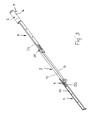
- Fig. 3
- in perspektivischer Darstellung den erfindungsgemäßen Antrieb in vollständig ausgefahrenem Zustand,
- Fig. 4
- die Einzelteile des erfindungsgemäßen Antriebs in perspektivischer Darstellung,
- Fig. 5
- in vergrößerter Darstellung ein Ende des erfindungsgemäßen Antriebs,
- Fig. 6
- ein Ende eines Zugbandes des Antriebes und das zugehörige Ende des Antriebes in schematischer Darstellung,
- Fig. 7
- in explosiver Darstellung eine zweite Ausführungsform eines erfindungsgemäßen Antriebs,
- Fig. 8
- eine zweite Ausführungsform eines Motors des erfindungsgemäßen Antriebes,
- Fig. 9
- den in einer Hubsäule untergebrachten erfindungsgemäßen Antrieb.
Claims (32)
- Höhenverstellbarer Antrieb, insbesondere für Möbel, mit wenigstens zwei gegeneinander verschiebbaren Teleskopteilen, die durch einen Motor betätigbar sind,
dadurch gekennzeichnet, daß der Antrieb wenigstens zwei relativ gegensinnig zueinander verstellbare Schubteile (19, 24) aufweist, die durch mindestens ein Zugelement (15, 16, 29, 40) miteinander verbunden sind. - Antrieb nach Anspruch 1,
dadurch gekennzeichnet, daß die Schubteile (19, 24) das eine Teleskopteil (2) bei eingefahrenem Antrieb wenigstens teilweise umgeben. - Antrieb nach Anspruch 1 oder 2,
dadurch gekennzeichnet, daß das eine Schubteil (19) mit einer Bodenstütze (60) fest verbunden ist. - Antrieb nach einem der Ansprüche 1 bis 3,
dadurch gekennzeichnet, daß das andere Schubteil (24) mit einem Gehäuse (6) des Motors (5) fest verbunden ist. - Antrieb nach einem der Ansprüche 1 bis 3,
dadurch gekennzeichnet, daß das andere Schubteil (24) mit dem zu verstellenden Teil (64), vorzugsweise einer Tischplatte, fest verbunden ist. - Antrieb nach einem der Ansprüche 1 bis 5,
dadurch gekennzeichnet, daß das eine Teleskopteil (2) wenigstens eine Führung (4, 39, 62) für wenigstens ein Schubteil (19, 24) aufweist. - Antrieb nach einem der Ansprüche 1 bis 6,
dadurch gekennzeichnet, daß das eine Teleskopteil (2) für beide Schubteile (19, 24) jeweils eine Führung (4, 39, 62) aufweist. - Antrieb nach einem der Ansprüche 1 bis 7,
dadurch gekennzeichnet, daß das Zugelement (15, 16, 29, 40) als Band ausgebildet ist. - Antrieb nach einem der Ansprüche 1 bis 8,
dadurch gekennzeichnet, daß die Zugelemente (15, 16, 29) mit einem Ende (17, 18, 30) am einen Schubteil (19) und mit ihrem anderen Ende (22, 23, 32) am anderen Schubteil (24) befestigt sind. - Antrieb nach Anspruch 9,
dadurch gekennzeichnet, daß das eine Ende (17, 18) des einen Zugelementes (15, 16) über eine gekrümmte Auflage (13, 14) des Führungsteiles (39) geführt ist. - Antrieb nach Anspruch 10,
dadurch gekennzeichnet, daß das Führungsteil (39) am einen Teleskopteil (2) befestigt ist. - Antrieb nach einem der Ansprüche 9 bis 11,
dadurch gekennzeichnet, daß das andere Ende (32) des anderen Zugelementes (29) über eine Umlenkrolle (28) geführt ist. - Antrieb nach Anspruch 12,
dadurch gekennzeichnet, daß die Umlenkrolle (28) an der einen Führung (4) des einen Teleskopteiles (2) frei drehbar ist. - Antrieb nach einem der Ansprüche 9 bis 13,
dadurch gekennzeichnet, daß das andere Ende (32) des anderen Zugelementes (20) durch wenigstens ein Spannelement (35, 36) vorgespannt ist. - Antrieb nach Anspruch 14,
dadurch gekennzeichnet, daß das Spannelement (35, 36) eine teilweise aus dem einen Schubteil (24) ausgestanzte Lasche ist. - Antrieb nach einem der Ansprüche 1 bis 8,
dadurch gekennzeichnet, daß das Zugelement (40) ein endlos umlaufendes Band ist. - Antrieb nach Anspruch 16,
dadurch gekennzeichnet, daß am einen Trum des Zugelementes (40) das eine Schubteil (19) und am anderen Trum das andere Schubteil (24) befestigt ist. - Antrieb nach Anspruch 16 oder 17,
dadurch gekennzeichnet, daß das Zugelement (40) über zwei am Teleskopteil (2) gelagerte Umlenkrollen (41, 42) geführt ist. - Antrieb nach Anspruch 18,
dadurch gekennzeichnet, daß die eine Umlenkrolle (42) in Längsrichtung des Zugelements (40) vorgespannt ist. - Antrieb nach einem der Ansprüche 1 bis 19,
dadurch gekennzeichnet, daß der Motor (5) eine Gewindespindel (9) drehbar antreibt, auf der eine mit dem einen Teleskopteil (2) verbundene Spindelmutter (10) sitzt. - Antrieb nach einem der Ansprüche 16 bis 20,
dadurch gekennzeichnet, daß die Umlenkrollen (28, 41, 42) eine ballige Auflagefläche für das Zugelement (29, 40) aufweisen. - Antrieb nach Anspruche 20 oder 21,
dadurch gekennzeichnet, daß die Gewindespindel (9) und die Spindelmutter (10) selbsthemmend ausgebildet sind. - Antrieb nach einem der Ansprüche 1 bis 22,
dadurch gekennzeichnet, daß der Motor (5) ein Stirnrad- oder Planetengetriebe aufweist. - Antrieb nach einem der Ansprüche 1 bis 22,
dadurch gekennzeichnet, daß der Motor (5) ein Winkel- oder ein Schneckengetriebe aufweist. - Antrieb nach Anspruch 23 oder 24,
dadurch gekennzeichnet, daß das Getriebe des Motors (5) selbsthemmend ist. - Antrieb nach einem der Ansprüche 1 bis 25,
dadurch gekennzeichnet, daß der Antrieb eine in einer Richtung wirkende Bremse aufweist. - Antrieb nach einem der Ansprüche 1 bis 26,
dadurch gekennzeichnet, daß der Motor (5) eine Drehzahl-Erkennungseinrichtung aufweist. - Antrieb nach Anspruch 27,
dadurch gekennzeichnet, daß die Drehzahl-Erkennungseinrichtung einen Impulsgeber, vorzugsweise einen Hall-Generator, aufweist. - Antrieb nach einem der Ansprüche 1 bis 28,
dadurch gekennzeichnet, daß der Motor (5) ein magnetisches Rastmoment aufweist. - Antrieb nach einem der Ansprüche 20 bis 29,
dadurch gekennzeichnet, daß die Spindelmutter (10) selbstschmierende Bestandteile hat. - Antrieb nach einem der Ansprüche 1 bis 30,
dadurch gekennzeichnet, daß die Verstellgeschwindigkeit der beiden Schubteile (19, 24) zueinander doppelt so groß ist wie die Verstellgeschwindigkeit des einen Teleskopteiles (2) gegenüber dem Motor (5). - Antrieb nach einem der Ansprüche 1 bis 31,
dadurch gekennzeichnet, daß die beiden Schubteile (19, 24) jeweils ein Teleskopteil (1, 3) des Antriebes bilden.
Priority Applications (1)
| Application Number | Priority Date | Filing Date | Title |
|---|---|---|---|
| DE202005021004U DE202005021004U1 (de) | 2004-04-08 | 2005-04-06 | Höhenverstellbarer Antrieb, insbesondere für Möbel |
Applications Claiming Priority (2)
| Application Number | Priority Date | Filing Date | Title |
|---|---|---|---|
| DE102004018428 | 2004-04-08 | ||
| DE200410018428 DE102004018428A1 (de) | 2004-04-08 | 2004-04-08 | Höhenverstellbarer Antrieb, insbesondere für Möbel |
Publications (2)
| Publication Number | Publication Date |
|---|---|
| EP1584264A1 true EP1584264A1 (de) | 2005-10-12 |
| EP1584264B1 EP1584264B1 (de) | 2017-02-01 |
Family
ID=34895586
Family Applications (1)
| Application Number | Title | Priority Date | Filing Date |
|---|---|---|---|
| EP05007488.9A Expired - Lifetime EP1584264B1 (de) | 2004-04-08 | 2005-04-06 | Höhenverstellbarer Antrieb, insbesondere für Möbel |
Country Status (3)
| Country | Link |
|---|---|
| EP (1) | EP1584264B1 (de) |
| DE (1) | DE102004018428A1 (de) |
| DK (1) | DK1584264T3 (de) |
Cited By (3)
| Publication number | Priority date | Publication date | Assignee | Title |
|---|---|---|---|---|
| WO2010009749A1 (de) * | 2008-07-25 | 2010-01-28 | Kesseböhmer Produktions GmbH & Co. KG | Verbindungsknoten und tragevorrichtung für eine tischplatte |
| US20110061570A1 (en) * | 2008-06-06 | 2011-03-17 | Norbert Klinke | Linear actuator |
| DE202013002313U1 (de) | 2013-03-08 | 2013-03-25 | Kesseböhmer Produktions GmbH & Co. KG | Mehrteilige teleskopierbare Säule mit Gasdruckfeder |
Families Citing this family (4)
| Publication number | Priority date | Publication date | Assignee | Title |
|---|---|---|---|---|
| DE102007057113A1 (de) * | 2007-11-26 | 2009-05-28 | Konrad Merkt Gmbh | Hubsäulen-Antrieb |
| DE102009015690A1 (de) | 2009-03-31 | 2010-10-07 | Logicdata Electronic & Software Entwicklungs Gmbh | Linearantrieb und Tisch mit Linearantrieb |
| DE102017125390A1 (de) * | 2017-10-30 | 2019-05-02 | Karsten Laing | Verfahren zum Erfassen des Belegungszustandes mindestens eines Möbelstücks und elektrisch verstellbares Möbelstück |
| DE102021200357B3 (de) | 2021-01-15 | 2022-06-09 | Kesseböhmer Holding Kg | Hubmechanik für einen höhenverstellbaren Tisch, höhenverstellbarer Tisch und Verfahren zum Betreiben einer Hubmechanik für einen höhenverstellbaren Tisch |
Citations (1)
| Publication number | Priority date | Publication date | Assignee | Title |
|---|---|---|---|---|
| WO2003003876A1 (en) * | 2001-07-04 | 2003-01-16 | Linak A/S | A drive unit, preferably for lifting columns for height-adjustable tables, and a lifting column |
Family Cites Families (2)
| Publication number | Priority date | Publication date | Assignee | Title |
|---|---|---|---|---|
| DE19841884A1 (de) * | 1998-09-11 | 2001-01-18 | Dietrich Gerhard Ellsaeser | Hubtisch |
| DE10216774B4 (de) * | 2002-04-15 | 2005-09-08 | Möckel Feinmechanik, Inh.: Holger Möckel | Höhenverstellbarer Tisch |
-
2004
- 2004-04-08 DE DE200410018428 patent/DE102004018428A1/de not_active Withdrawn
-
2005
- 2005-04-06 EP EP05007488.9A patent/EP1584264B1/de not_active Expired - Lifetime
- 2005-04-06 DK DK05007488.9T patent/DK1584264T3/en active
Patent Citations (1)
| Publication number | Priority date | Publication date | Assignee | Title |
|---|---|---|---|---|
| WO2003003876A1 (en) * | 2001-07-04 | 2003-01-16 | Linak A/S | A drive unit, preferably for lifting columns for height-adjustable tables, and a lifting column |
Cited By (4)
| Publication number | Priority date | Publication date | Assignee | Title |
|---|---|---|---|---|
| US20110061570A1 (en) * | 2008-06-06 | 2011-03-17 | Norbert Klinke | Linear actuator |
| US9155391B2 (en) * | 2008-06-06 | 2015-10-13 | Linak A/S | Linear actuator |
| WO2010009749A1 (de) * | 2008-07-25 | 2010-01-28 | Kesseböhmer Produktions GmbH & Co. KG | Verbindungsknoten und tragevorrichtung für eine tischplatte |
| DE202013002313U1 (de) | 2013-03-08 | 2013-03-25 | Kesseböhmer Produktions GmbH & Co. KG | Mehrteilige teleskopierbare Säule mit Gasdruckfeder |
Also Published As
| Publication number | Publication date |
|---|---|
| EP1584264B1 (de) | 2017-02-01 |
| DE102004018428A1 (de) | 2005-10-27 |
| DK1584264T3 (en) | 2017-03-13 |
Similar Documents
| Publication | Publication Date | Title |
|---|---|---|
| DE60204493T2 (de) | Hebesäule vorzugsweise für Möbel wie Tische und Betten | |
| EP2873344A1 (de) | Möbel mit höhenverstellbarem Bein | |
| DE29919877U1 (de) | Elektromotorische Verstelleinrichtung | |
| EP3981288A1 (de) | Hubsäule für ein möbel | |
| EP3717797A1 (de) | Teleskopierbarer linearaktuator und höhenverstellbarer tisch | |
| DE60314498T2 (de) | Antriebsmechanismus für einen körper auf schienen | |
| EP1584264B1 (de) | Höhenverstellbarer Antrieb, insbesondere für Möbel | |
| EP1097657B1 (de) | Teleskopantriebseinheit | |
| DE102007057113A1 (de) | Hubsäulen-Antrieb | |
| DE202005021004U1 (de) | Höhenverstellbarer Antrieb, insbesondere für Möbel | |
| EP1233209A1 (de) | Verschiebeeinrichtung mit einem eine Zahnstange eingreifenden Zahnriemen | |
| EP4176770B1 (de) | Antriebssystem für eine linear bewegte ausziehbare möbelkomponente | |
| DE29802535U1 (de) | Elektromotorischer Linearantrieb | |
| DE10021898C2 (de) | Vorrichtung zum Verstellen von relativ zueinander beweglichen Teilen | |
| DE102023105700A1 (de) | Translations-Rotations-Beschlag und Möbel- oder Haushaltsgeräteelement | |
| CH693161A5 (de) | Ausziehvorrichtung eines Hochschrankes. | |
| DE29720337U1 (de) | Antriebsanordnung einer elektromotorischen Höhenverstelleinrichtung | |
| DE2618558A1 (de) | Hoehenverstellaggregat, insbesondere fuer tische | |
| EP0901760B1 (de) | Auszugschiene und Ausziehtisch mit einer solchen Auszugschiene | |
| DE10222995C1 (de) | Verstellantrieb für Kraftfahrzeugsitzteile | |
| DE29922626U1 (de) | Universelles Gestell für höhenverstellbare Tische mit einer oder mehrerer Tischplatten in weitestgehend beliebiger Form | |
| DE202007003378U1 (de) | Spiegelanordnung mit einem Grundkörper und einer Spiegeleinheit | |
| DE2912955C2 (de) | Führungseinrichtung für die Beine eines höhenverstellbaren Tisches | |
| DE10220071C1 (de) | Vorrichtung zur linearen Hubverstellung | |
| DE10024431A1 (de) | Vorrichtung zur Höhenverstellung eines Möbelstücks |
Legal Events
| Date | Code | Title | Description |
|---|---|---|---|
| PUAI | Public reference made under article 153(3) epc to a published international application that has entered the european phase |
Free format text: ORIGINAL CODE: 0009012 |
|
| AK | Designated contracting states |
Kind code of ref document: A1 Designated state(s): AT BE BG CH CY CZ DE DK EE ES FI FR GB GR HU IE IS IT LI LT LU MC NL PL PT RO SE SI SK TR |
|
| AX | Request for extension of the european patent |
Extension state: AL BA HR LV MK YU |
|
| 17P | Request for examination filed |
Effective date: 20060406 |
|
| AKX | Designation fees paid |
Designated state(s): AT DE DK |
|
| REG | Reference to a national code |
Ref country code: DE Ref legal event code: R138 Ref document number: 202005021004 Country of ref document: DE Free format text: GERMAN DOCUMENT NUMBER IS 502005015502 |
|
| RAP1 | Party data changed (applicant data changed or rights of an application transferred) |
Owner name: KESSEBOEHMER PRODUKTIONS GMBH + CO. KG |
|
| 17Q | First examination report despatched |
Effective date: 20120124 |
|
| GRAP | Despatch of communication of intention to grant a patent |
Free format text: ORIGINAL CODE: EPIDOSNIGR1 |
|
| GRAJ | Information related to disapproval of communication of intention to grant by the applicant or resumption of examination proceedings by the epo deleted |
Free format text: ORIGINAL CODE: EPIDOSDIGR1 |
|
| INTG | Intention to grant announced |
Effective date: 20160726 |
|
| GRAP | Despatch of communication of intention to grant a patent |
Free format text: ORIGINAL CODE: EPIDOSNIGR1 |
|
| INTC | Intention to grant announced (deleted) | ||
| INTG | Intention to grant announced |
Effective date: 20160901 |
|
| GRAS | Grant fee paid |
Free format text: ORIGINAL CODE: EPIDOSNIGR3 |
|
| GRAA | (expected) grant |
Free format text: ORIGINAL CODE: 0009210 |
|
| AK | Designated contracting states |
Kind code of ref document: B1 Designated state(s): AT DE DK |
|
| REG | Reference to a national code |
Ref country code: DE Ref legal event code: R081 Ref document number: 502005015502 Country of ref document: DE Owner name: KESSEBOEHMER HOLDING KG, DE Free format text: FORMER OWNER: KESSEBOEHMER PRODUKTIONS GMBH, 73235 WEILHEIM, DE |
|
| REG | Reference to a national code |
Ref country code: AT Ref legal event code: REF Ref document number: 864831 Country of ref document: AT Kind code of ref document: T Effective date: 20170215 |
|
| REG | Reference to a national code |
Ref country code: DK Ref legal event code: T3 Effective date: 20170306 |
|
| REG | Reference to a national code |
Ref country code: DE Ref legal event code: R096 Ref document number: 502005015502 Country of ref document: DE |
|
| REG | Reference to a national code |
Ref country code: DE Ref legal event code: R097 Ref document number: 502005015502 Country of ref document: DE |
|
| PLBE | No opposition filed within time limit |
Free format text: ORIGINAL CODE: 0009261 |
|
| STAA | Information on the status of an ep patent application or granted ep patent |
Free format text: STATUS: NO OPPOSITION FILED WITHIN TIME LIMIT |
|
| 26N | No opposition filed |
Effective date: 20171103 |
|
| PGFP | Annual fee paid to national office [announced via postgrant information from national office to epo] |
Ref country code: AT Payment date: 20200421 Year of fee payment: 16 |
|
| REG | Reference to a national code |
Ref country code: AT Ref legal event code: MM01 Ref document number: 864831 Country of ref document: AT Kind code of ref document: T Effective date: 20210406 |
|
| PG25 | Lapsed in a contracting state [announced via postgrant information from national office to epo] |
Ref country code: AT Free format text: LAPSE BECAUSE OF NON-PAYMENT OF DUE FEES Effective date: 20210406 |
|
| REG | Reference to a national code |
Ref country code: DE Ref legal event code: R081 Ref document number: 502005015502 Country of ref document: DE Owner name: KESSEBOEHMER HOLDING KG, DE Free format text: FORMER OWNER: KESSEBOEHMER PRODUKTIONS GMBH + CO. KG, 73235 WEILHEIM, DE |
|
| PGFP | Annual fee paid to national office [announced via postgrant information from national office to epo] |
Ref country code: DK Payment date: 20230419 Year of fee payment: 19 Ref country code: DE Payment date: 20230427 Year of fee payment: 19 |
|
| REG | Reference to a national code |
Ref country code: DE Ref legal event code: R119 Ref document number: 502005015502 Country of ref document: DE |
|
| REG | Reference to a national code |
Ref country code: DK Ref legal event code: EBP Effective date: 20240430 |
|
| PG25 | Lapsed in a contracting state [announced via postgrant information from national office to epo] |
Ref country code: DE Free format text: LAPSE BECAUSE OF NON-PAYMENT OF DUE FEES Effective date: 20241105 |
|
| PG25 | Lapsed in a contracting state [announced via postgrant information from national office to epo] |
Ref country code: DE Free format text: LAPSE BECAUSE OF NON-PAYMENT OF DUE FEES Effective date: 20241105 |
|
| PG25 | Lapsed in a contracting state [announced via postgrant information from national office to epo] |
Ref country code: DK Free format text: LAPSE BECAUSE OF NON-PAYMENT OF DUE FEES Effective date: 20240430 |