EP1584305A2 - In eine Ader des Blutkreislaufs einführbarer Katheter - Google Patents
In eine Ader des Blutkreislaufs einführbarer Katheter Download PDFInfo
- Publication number
- EP1584305A2 EP1584305A2 EP05007792A EP05007792A EP1584305A2 EP 1584305 A2 EP1584305 A2 EP 1584305A2 EP 05007792 A EP05007792 A EP 05007792A EP 05007792 A EP05007792 A EP 05007792A EP 1584305 A2 EP1584305 A2 EP 1584305A2
- Authority
- EP
- European Patent Office
- Prior art keywords
- catheter according
- distal end
- constriction
- catheter
- vein
- Prior art date
- Legal status (The legal status is an assumption and is not a legal conclusion. Google has not performed a legal analysis and makes no representation as to the accuracy of the status listed.)
- Granted
Links
Images



Classifications
-
- A—HUMAN NECESSITIES
- A61—MEDICAL OR VETERINARY SCIENCE; HYGIENE
- A61M—DEVICES FOR INTRODUCING MEDIA INTO, OR ONTO, THE BODY; DEVICES FOR TRANSDUCING BODY MEDIA OR FOR TAKING MEDIA FROM THE BODY; DEVICES FOR PRODUCING OR ENDING SLEEP OR STUPOR
- A61M25/00—Catheters; Hollow probes
- A61M25/0067—Catheters; Hollow probes characterised by the distal end, e.g. tips
- A61M25/0068—Static characteristics of the catheter tip, e.g. shape, atraumatic tip, curved tip or tip structure
-
- A—HUMAN NECESSITIES
- A61—MEDICAL OR VETERINARY SCIENCE; HYGIENE
- A61B—DIAGNOSIS; SURGERY; IDENTIFICATION
- A61B17/00—Surgical instruments, devices or methods
- A61B17/11—Surgical instruments, devices or methods for performing anastomosis; Buttons for anastomosis
-
- A—HUMAN NECESSITIES
- A61—MEDICAL OR VETERINARY SCIENCE; HYGIENE
- A61F—FILTERS IMPLANTABLE INTO BLOOD VESSELS; PROSTHESES; DEVICES PROVIDING PATENCY TO, OR PREVENTING COLLAPSING OF, TUBULAR STRUCTURES OF THE BODY, e.g. STENTS; ORTHOPAEDIC, NURSING OR CONTRACEPTIVE DEVICES; FOMENTATION; TREATMENT OR PROTECTION OF EYES OR EARS; BANDAGES, DRESSINGS OR ABSORBENT PADS; FIRST-AID KITS
- A61F2/00—Filters implantable into blood vessels; Prostheses, i.e. artificial substitutes or replacements for parts of the body; Appliances for connecting them with the body; Devices providing patency to, or preventing collapsing of, tubular structures of the body, e.g. stents
- A61F2/02—Prostheses implantable into the body
- A61F2/04—Hollow or tubular parts of organs, e.g. bladders, tracheae, bronchi or bile ducts
- A61F2/06—Blood vessels
- A61F2/07—Stent-grafts
-
- A—HUMAN NECESSITIES
- A61—MEDICAL OR VETERINARY SCIENCE; HYGIENE
- A61F—FILTERS IMPLANTABLE INTO BLOOD VESSELS; PROSTHESES; DEVICES PROVIDING PATENCY TO, OR PREVENTING COLLAPSING OF, TUBULAR STRUCTURES OF THE BODY, e.g. STENTS; ORTHOPAEDIC, NURSING OR CONTRACEPTIVE DEVICES; FOMENTATION; TREATMENT OR PROTECTION OF EYES OR EARS; BANDAGES, DRESSINGS OR ABSORBENT PADS; FIRST-AID KITS
- A61F2/00—Filters implantable into blood vessels; Prostheses, i.e. artificial substitutes or replacements for parts of the body; Appliances for connecting them with the body; Devices providing patency to, or preventing collapsing of, tubular structures of the body, e.g. stents
- A61F2/95—Instruments specially adapted for placement or removal of stents or stent-grafts
-
- A—HUMAN NECESSITIES
- A61—MEDICAL OR VETERINARY SCIENCE; HYGIENE
- A61M—DEVICES FOR INTRODUCING MEDIA INTO, OR ONTO, THE BODY; DEVICES FOR TRANSDUCING BODY MEDIA OR FOR TAKING MEDIA FROM THE BODY; DEVICES FOR PRODUCING OR ENDING SLEEP OR STUPOR
- A61M25/00—Catheters; Hollow probes
- A61M25/0067—Catheters; Hollow probes characterised by the distal end, e.g. tips
- A61M25/0068—Static characteristics of the catheter tip, e.g. shape, atraumatic tip, curved tip or tip structure
- A61M25/0069—Tip not integral with tube
-
- A—HUMAN NECESSITIES
- A61—MEDICAL OR VETERINARY SCIENCE; HYGIENE
- A61M—DEVICES FOR INTRODUCING MEDIA INTO, OR ONTO, THE BODY; DEVICES FOR TRANSDUCING BODY MEDIA OR FOR TAKING MEDIA FROM THE BODY; DEVICES FOR PRODUCING OR ENDING SLEEP OR STUPOR
- A61M25/00—Catheters; Hollow probes
- A61M25/0067—Catheters; Hollow probes characterised by the distal end, e.g. tips
- A61M25/0082—Catheter tip comprising a tool
-
- A—HUMAN NECESSITIES
- A61—MEDICAL OR VETERINARY SCIENCE; HYGIENE
- A61B—DIAGNOSIS; SURGERY; IDENTIFICATION
- A61B17/00—Surgical instruments, devices or methods
- A61B17/00234—Surgical instruments, devices or methods for minimally invasive surgery
- A61B2017/00238—Type of minimally invasive operation
- A61B2017/00243—Type of minimally invasive operation cardiac
- A61B2017/00247—Making holes in the wall of the heart, e.g. laser Myocardial revascularization
- A61B2017/00252—Making holes in the wall of the heart, e.g. laser Myocardial revascularization for by-pass connections, i.e. connections from heart chamber to blood vessel or from blood vessel to blood vessel
-
- A—HUMAN NECESSITIES
- A61—MEDICAL OR VETERINARY SCIENCE; HYGIENE
- A61B—DIAGNOSIS; SURGERY; IDENTIFICATION
- A61B17/00—Surgical instruments, devices or methods
- A61B17/11—Surgical instruments, devices or methods for performing anastomosis; Buttons for anastomosis
- A61B2017/1107—Surgical instruments, devices or methods for performing anastomosis; Buttons for anastomosis for blood vessels
-
- A—HUMAN NECESSITIES
- A61—MEDICAL OR VETERINARY SCIENCE; HYGIENE
- A61B—DIAGNOSIS; SURGERY; IDENTIFICATION
- A61B17/00—Surgical instruments, devices or methods
- A61B17/22—Implements for squeezing-off ulcers or the like on inner organs of the body; Implements for scraping-out cavities of body organs, e.g. bones; for invasive removal or destruction of calculus using mechanical vibrations; for removing obstructions in blood vessels, not otherwise provided for
- A61B2017/22051—Implements for squeezing-off ulcers or the like on inner organs of the body; Implements for scraping-out cavities of body organs, e.g. bones; for invasive removal or destruction of calculus using mechanical vibrations; for removing obstructions in blood vessels, not otherwise provided for with an inflatable part, e.g. balloon, for positioning, blocking, or immobilisation
- A61B2017/22065—Functions of balloons
- A61B2017/22069—Immobilising; Stabilising
-
- A—HUMAN NECESSITIES
- A61—MEDICAL OR VETERINARY SCIENCE; HYGIENE
- A61F—FILTERS IMPLANTABLE INTO BLOOD VESSELS; PROSTHESES; DEVICES PROVIDING PATENCY TO, OR PREVENTING COLLAPSING OF, TUBULAR STRUCTURES OF THE BODY, e.g. STENTS; ORTHOPAEDIC, NURSING OR CONTRACEPTIVE DEVICES; FOMENTATION; TREATMENT OR PROTECTION OF EYES OR EARS; BANDAGES, DRESSINGS OR ABSORBENT PADS; FIRST-AID KITS
- A61F2/00—Filters implantable into blood vessels; Prostheses, i.e. artificial substitutes or replacements for parts of the body; Appliances for connecting them with the body; Devices providing patency to, or preventing collapsing of, tubular structures of the body, e.g. stents
- A61F2/02—Prostheses implantable into the body
- A61F2/04—Hollow or tubular parts of organs, e.g. bladders, tracheae, bronchi or bile ducts
- A61F2/06—Blood vessels
- A61F2/064—Blood vessels with special features to facilitate anastomotic coupling
-
- A—HUMAN NECESSITIES
- A61—MEDICAL OR VETERINARY SCIENCE; HYGIENE
- A61F—FILTERS IMPLANTABLE INTO BLOOD VESSELS; PROSTHESES; DEVICES PROVIDING PATENCY TO, OR PREVENTING COLLAPSING OF, TUBULAR STRUCTURES OF THE BODY, e.g. STENTS; ORTHOPAEDIC, NURSING OR CONTRACEPTIVE DEVICES; FOMENTATION; TREATMENT OR PROTECTION OF EYES OR EARS; BANDAGES, DRESSINGS OR ABSORBENT PADS; FIRST-AID KITS
- A61F2/00—Filters implantable into blood vessels; Prostheses, i.e. artificial substitutes or replacements for parts of the body; Appliances for connecting them with the body; Devices providing patency to, or preventing collapsing of, tubular structures of the body, e.g. stents
- A61F2/82—Devices providing patency to, or preventing collapsing of, tubular structures of the body, e.g. stents
- A61F2/848—Devices providing patency to, or preventing collapsing of, tubular structures of the body, e.g. stents having means for fixation to the vessel wall, e.g. barbs
-
- A—HUMAN NECESSITIES
- A61—MEDICAL OR VETERINARY SCIENCE; HYGIENE
- A61F—FILTERS IMPLANTABLE INTO BLOOD VESSELS; PROSTHESES; DEVICES PROVIDING PATENCY TO, OR PREVENTING COLLAPSING OF, TUBULAR STRUCTURES OF THE BODY, e.g. STENTS; ORTHOPAEDIC, NURSING OR CONTRACEPTIVE DEVICES; FOMENTATION; TREATMENT OR PROTECTION OF EYES OR EARS; BANDAGES, DRESSINGS OR ABSORBENT PADS; FIRST-AID KITS
- A61F2/00—Filters implantable into blood vessels; Prostheses, i.e. artificial substitutes or replacements for parts of the body; Appliances for connecting them with the body; Devices providing patency to, or preventing collapsing of, tubular structures of the body, e.g. stents
- A61F2/82—Devices providing patency to, or preventing collapsing of, tubular structures of the body, e.g. stents
- A61F2/848—Devices providing patency to, or preventing collapsing of, tubular structures of the body, e.g. stents having means for fixation to the vessel wall, e.g. barbs
- A61F2002/8486—Devices providing patency to, or preventing collapsing of, tubular structures of the body, e.g. stents having means for fixation to the vessel wall, e.g. barbs provided on at least one of the ends
-
- A—HUMAN NECESSITIES
- A61—MEDICAL OR VETERINARY SCIENCE; HYGIENE
- A61F—FILTERS IMPLANTABLE INTO BLOOD VESSELS; PROSTHESES; DEVICES PROVIDING PATENCY TO, OR PREVENTING COLLAPSING OF, TUBULAR STRUCTURES OF THE BODY, e.g. STENTS; ORTHOPAEDIC, NURSING OR CONTRACEPTIVE DEVICES; FOMENTATION; TREATMENT OR PROTECTION OF EYES OR EARS; BANDAGES, DRESSINGS OR ABSORBENT PADS; FIRST-AID KITS
- A61F2/00—Filters implantable into blood vessels; Prostheses, i.e. artificial substitutes or replacements for parts of the body; Appliances for connecting them with the body; Devices providing patency to, or preventing collapsing of, tubular structures of the body, e.g. stents
- A61F2/95—Instruments specially adapted for placement or removal of stents or stent-grafts
- A61F2002/9534—Instruments specially adapted for placement or removal of stents or stent-grafts for repositioning of stents
-
- A—HUMAN NECESSITIES
- A61—MEDICAL OR VETERINARY SCIENCE; HYGIENE
- A61F—FILTERS IMPLANTABLE INTO BLOOD VESSELS; PROSTHESES; DEVICES PROVIDING PATENCY TO, OR PREVENTING COLLAPSING OF, TUBULAR STRUCTURES OF THE BODY, e.g. STENTS; ORTHOPAEDIC, NURSING OR CONTRACEPTIVE DEVICES; FOMENTATION; TREATMENT OR PROTECTION OF EYES OR EARS; BANDAGES, DRESSINGS OR ABSORBENT PADS; FIRST-AID KITS
- A61F2250/00—Special features of prostheses classified in groups A61F2/00 - A61F2/26 or A61F2/82 or A61F9/00 or A61F11/00 or subgroups thereof
- A61F2250/0014—Special features of prostheses classified in groups A61F2/00 - A61F2/26 or A61F2/82 or A61F9/00 or A61F11/00 or subgroups thereof having different values of a given property or geometrical feature, e.g. mechanical property or material property, at different locations within the same prosthesis
- A61F2250/0037—Special features of prostheses classified in groups A61F2/00 - A61F2/26 or A61F2/82 or A61F9/00 or A61F11/00 or subgroups thereof having different values of a given property or geometrical feature, e.g. mechanical property or material property, at different locations within the same prosthesis differing in height or in length
-
- A—HUMAN NECESSITIES
- A61—MEDICAL OR VETERINARY SCIENCE; HYGIENE
- A61M—DEVICES FOR INTRODUCING MEDIA INTO, OR ONTO, THE BODY; DEVICES FOR TRANSDUCING BODY MEDIA OR FOR TAKING MEDIA FROM THE BODY; DEVICES FOR PRODUCING OR ENDING SLEEP OR STUPOR
- A61M25/00—Catheters; Hollow probes
- A61M25/01—Introducing, guiding, advancing, emplacing or holding catheters
- A61M25/02—Holding devices, e.g. on the body
- A61M25/04—Holding devices, e.g. on the body in the body, e.g. expansible
Definitions
- the invention relates to a in a vein of the bloodstream insertable catheter, in particular for myocardial revascularization by partial arterialization of the coronary sinus, the one with at least one expandable Anchoring element at its distal end for anchoring on the vein wall and a tubular sleeve (Sheet) which is pushed onto the Konduit, after insertion of the conduit into the vein, at least proximally is partially retractable and at least one Anchoring element releases, so that this expand can.
- a tubular sleeve Sheet
- Consequences of coronary heart disease with constriction or Closure of coronary vessels accounts for about 30% of all deaths the leading cause of death in all industrialized countries. More than 340,000 people die each year in Germany as a result of coronary heart disease.
- the aorto-coronary Bypass surgery is an established therapy procedure for the treatment of coronary heart disease, in particular if several coronary arteries are affected by the disease are. In Germany, about 70,000 bypass operations per year carried out. Around 60% of patients who undergoing a bypass operation for the first time, are between 50 and 69 years old.
- the aorto-coronary bypass surgery is usually after opening the thorax and connecting the patient performed on the heart-lung machine. Usually will the heart during the procedure after clamping of the main artery immobilized for about 30 to 50 minutes.
- a catheter system introduced into the jugular vein and advanced into the right atrium of the heart.
- the Catheter system carries a patient's own vein bypass, or a tubular prosthesis made of a known material, such as. Dacron, PTFE or similar, d. H. a condo, that led to the coronary sinus and anchored there becomes.
- a tubular prosthesis made of a known material, such as. Dacron, PTFE or similar, d. H. a condo, that led to the coronary sinus and anchored there becomes.
- the free end of the Konduits by the right antechamber retracted into the jugular vein and over this discharged.
- the free is diverted End of the carotid with the carotid artery, which is next to the jugular vein is connected.
- a bloodstream established from a central artery to the coronary sinus, d. H. a blood flow that is the direction of flow of the Coronary sinus is opposite.
- the object of the invention is to provide a Catheter, where a solution of anchoring and damage the wire can be avoided when pulling out the sleeve can.
- the solution according to the invention is that the Konduit at its distal end with a narrowing of its lumen is provided and the catheter on a guidewire having push-on tubular element (pusher), which rests against the constriction at its front end.
- the catheter of the invention may be like a previously known catheter into the vein on a previously inserted guidewire be inserted. If the sleeve is then withdrawn, in order to release the anchoring element (s) the distal end of the conduit through the tubular member (Pusher) held in place, so no Tensile forces act on the anchorage. Then you can then pulled the tubular element out of the conduit become. There are no large tractive forces, since the tubular elements on the guidewire and within the condoms can slide without much resistance, which, for example, by suitable surface coating can be achieved.
- anchoring elements can resilient elements, in particular Elastic hooks are used in the Hook the wall of the wire when retracting the sleeve.
- the hooks extend in an advantageous manner from Conduit to the distal and to the outside. In this case, one is Repositioning possible by moving the sleeve forward again pushed and squeezes the hooks, then what the catheter is pushed further in or pulled out can. In another advantageous embodiment, in which the hooks from the condyle to the proximal and to extend outside, this is not possible. But you have greater security against unintentional withdrawal, because the hooks in this case tighter in the wall of the vein intervention.
- the hooks are rounded at their front ends, a violation of the vein is avoided.
- the hooks are only one-sided on the circumference provided the Konduits. You can do so well in the myocardium was anchored while the other side of the vein, which is very thin, does not get damaged.
- the anchoring element a spiral, which after retreating the Sleeve expands.
- the tubular element is advantageously made Plastic or carbon-like material, in particular Polytetrafluoroethylene, which is the advantage especially low Has friction forces.
- Another advantageous embodiment is characterized by the fact that the tubular element made of metal, in particular a very flexible, thin-walled Metal tube (cannula tube) consists.
- constriction is part of the condyle.
- narrowing in the form of a Head piece formed on the distal end of the conduit is attached.
- the constriction is advantageously and the distal end of the tubular member with complementary Provided rotary connection devices.
- Rotating the tubular element can do this with the constriction be connected, so that the tubular element not only a compressive force, but also a pulling force to Repositioning the catheter can exercise.
- the rotary connection devices can thread or bayonet connections be.
- the connection of the tubular element with the Konduit or a head piece of the Konduits can also be formed on one side (eccentric).
- the condyle settles on his distal end sealingly against the wall of the vein, leaving in the case of the application mentioned in the opposite direction no blood can flow. In other cases it can be advantageous if at least some backflow in the opposite direction is possible. In this case it lies distal end of the conduit in other embodiments not sealing against the wall of the vein.
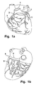
- a human heart is shown schematically. From the aorta 1 u.a. through an opening 2 Blood into the coronary vessels 3 and thus supplies the heart muscles. The returning blood comes from the coronary vein 5 and various side branches 6, accumulates in the coronary sinus 4 and drain into the right atrium. At advanced coronary heart disease or relapse surgery can change the coronary vessels in your course so massive be that sewing a bypass on the Kranzader technically not possible. For these patients is a revascularization of the coronary arteries possible by Arterial blood supplied "from behind" the coronary vessels becomes, so over the Koronarsinus.
- the Konduit 7 extends from the coronary sinus the right atrium and through the superior vena cava 9 in one large central or peripheral artery (usually the Carotid artery) 10.
- the transition from venous to arterial Vessel prepares no special difficulties and is usual surgical practice, so do not care must be discussed in more detail.
- At the distal end 8 must Konduit but anchored in the coronary sinus 4. This anchorage you will often make sealing, as in the Coronary sinus still lead small veins 6. In other cases But it is not desirable here a complete seal to create a certain backflow of venous blood to obtain.
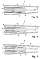
- FIG. 3 shows the distal end region 8 of a cable 7. which is inserted into a wire 4. To this end previously a guide wire 11 was inserted into the wire 4 Service.
- the condyle 7 is at its distal end 8 with a Headpiece 12 provided. At this are outside on the circumference hook-shaped anchoring elements 13 provided by a deferred sleeve 14 held together against its bias become.
- a tubular Element 15 which extends to the proximal end of the Catheter extends.
- This tubular member 15, the hereinafter also referred to as a pusher, exercises a counterforce on the head piece 12, when the sleeve 14 is retracted is to release the anchoring elements 13.
- anchoring elements 13 In the embodiments of Fig. 6, those are in the header 12 arranged anchoring elements 13 rounded at their ends, so the risk of damaging the wall of the Core 4 is smaller.
- Fig. 7 In the embodiment of Fig. 7 is an anchoring element 13 in the form of a spiral in the head piece 12 provided.
- Fig. 8 shows the distal end portion 8 of the cable 7, the was provided with a diameter constriction 17 was against which the pusher 15 can rest.
- Fig. 9 is finally a rotary joint device 16 is shown, with the the pusher 15 and the head 12 by turning the pusher 15 can be connected so that by the Pusher 15 also exerted a pulling force on the head piece 12 can be.
- This rotary joint can on the one hand a thread be.
- a bayonet connection could be provided.
- This figure also shows that the Anchoring elements 13 only on one side of the head piece 12 are arranged.
- Fig. 10 shows in cross-section the end region 8 of the conduit 7.
- the diameter constriction 17 does not extend around the entire inner circumference of the Konduits, but consists in essentially two projections, against which the pusher 15 is applied.
- the diameter narrowing 17 thus narrows the lumen less and obstructs the blood flow less.
- Fig. 11 is a similar view as shown in Fig. 9.
- the constriction 17 im consists essentially of here pin-shaped projections 16 of a bayonet closure, its complementary recesses at the end of the tubular Element 15 are shown in FIG.
Landscapes
- Health & Medical Sciences (AREA)
- Life Sciences & Earth Sciences (AREA)
- Engineering & Computer Science (AREA)
- Biomedical Technology (AREA)
- Veterinary Medicine (AREA)
- Heart & Thoracic Surgery (AREA)
- Animal Behavior & Ethology (AREA)
- General Health & Medical Sciences (AREA)
- Public Health (AREA)
- Pulmonology (AREA)
- Anesthesiology (AREA)
- Hematology (AREA)
- Biophysics (AREA)
- Cardiology (AREA)
- Oral & Maxillofacial Surgery (AREA)
- Transplantation (AREA)
- Vascular Medicine (AREA)
- Surgery (AREA)
- Nuclear Medicine, Radiotherapy & Molecular Imaging (AREA)
- Medical Informatics (AREA)
- Molecular Biology (AREA)
- Gastroenterology & Hepatology (AREA)
- Prostheses (AREA)
- Media Introduction/Drainage Providing Device (AREA)
Abstract
Description
- Fig. 1a und 1b
- eine schematische Darstellung des Herzens mit den relevanten Blutgefäßen;
- Fig. 2
- in schematischer Darstellung das Prinzip des Einbringens eines Konduits;
- Fig. 3
- im Querschnitt der distale Endbereich eines Katheters, der in eine Ader eingeschoben ist, bevor die Hülse zurückgezogen ist;
- Fig. 4
- in ähnlicher Darstellung sie in Fig. 3 den distalen Endbereich eines Katheters, nachdem die Hülse zum Freigeben der Verankerungselemente teilweise zurückgezogen ist;
- Fig. 5
- in ähnlicher Darstellung wie in den Fig. 3 und 4 eine alternative Ausführungsform;
- Fig. 6
- eine Ausführungsform mit am Ende abgerundeten Verankerungselemente;
- Fig. 7
- in ähnlicher Darstellung wie in den Fig. 3 bis 5 eine Ausführungsform mit einem alternativen Verankerungselement;
- Fig. 8
- ein Konduit mit einem verengten distalen Endbereich;
- Fig. 9
- eine alternative Ausführungsform mit einer Drehverbindungseinrichtung von Pusher und Kopfstück; und
- Fig. 10-12
- alternative Ausführungsformen der Verengung beziehungsweise Drehverbindungseinrichtung.
Claims (16)
- In eine Ader (4) des Blutkreislaufs einführbarer Katheter, insbesondere zur Myokardrevaskularisation durch partielle Arterialisierung des Koronarsinus, der ein Konduit (7) mit wenigstens einem expandierbaren Verankerungselement (13) an seinem distalen Ende (8) zum Verankern an der Aderwand und eine schlauchförmige Hülse (Sheet 14) aufweist, die auf das Konduit (7) aufgeschoben ist, nach Einbringung des Konduits (7) in die Ader (4) nach proximal wenigstens teilweise zurückziehbar ist und dabei das wenigstens eine Verankerungselement (13) freigibt, so dass dieses expandieren kann, dadurch gekennzeichnet, dass das Konduit (7) an seinem distalen Ende (8) mit einer Verengung (17) seines Lumens versehen ist und der Katheter ein auf einen Führungsdraht (11) aufschiebbares röhrenförmiges Element (Pusher 15) aufweist, das an seinem vorderen Ende gegen die Verengung (17) anliegt.
- Katheter nach Anspruch 1, dadurch gekennzeichnet, dass mehrere Verankerungselemente (13) in Form von federnden Elementen, insbesondere elastischen Haken vorgesehen sind.
- Katheter nach Anspruch 2, dadurch gekennzeichnet, dass die Haken (13) sich vom Konduit (7) nach distal und nach außen erstrecken.
- Katheter nach Anspruch 2, dadurch gekennzeichnet, dass sich die Haken (13) vom Konduit (7) nach proximal und nach außen erstrecken.
- Katheter nach einem der Ansprüche 2 bis 4, dadurch gekennzeichnete, dass die Haken (13) an ihrem vorderen Ende abgerundet sind.
- Katheter nach einem der Ansprüche 2 bis 5, dadurch gekennzeichnet, dass die Haken (13) nur auf einer Seite des Umfangs des Konduits angeordnet sind.
- Katheter nach Anspruch 1, dadurch gekennzeichnet, dass das Verankerungselement (13) eine Spirale ist.
- Katheter nach einem der Ansprüche 1 bis 7, dadurch gekennzeichnet, dass das röhrenförmige Element (Pusher 15) aus Kunststoff oder kunststoffartigem Material ist.
- Katheter nach einem der Ansprüche 1 bis 8, dadurch gekennzeichnet, dass das röhrenförmige Element (Pusher 15) aus Polytetrafluorethylen ist.
- Katheter nach einem der Ansprüche 1 bis 9, dadurch gekennzeichnet, dass das röhrenförmige Element (15) aus flexiblem, dünnwandigen Metall besteht.
- Katheter nach einem der Ansprüche 1 bis 10, dadurch gekennzeichnet, dass die Verengung (17) des Lumens im distalen Endbereich (8) des Konduits (7) ausgebildet ist.
- Katheter nach einem der Ansprüche 1 bis 10, dadurch gekennzeichnet, dass das Konduit (7) an seinem distalen Ende (8) ein mit der Verengung (17) versehenes Kopfstück (12) aufweist.
- Katheter nach einem der Ansprüche 1 bis 12, dadurch gekennzeichnet, dass die Verengung (17) und das distal Ende des röhrenförmigen Elements (Pusher 15) mit komplementären Drehverbindungseinrichtungen (16) versehen sind.
- Katheter nach Anspruch 13, dadurch gekennzeichnet, dass die komplementären Drehverbindungseinrichtungen (16) Gewinde sind.
- Katheter nach Anspruch 13, dadurch gekennzeichnet, dass die komplementären Drehverbindungseinrichtungen (16) Bajonettverbindungen sind.
- Katheter nach einem der Ansprüche 1 bis 15, dadurch gekennzeichnet, dass sich die Verengung (17) und/oder die Drehverbindungseinrichtungen (16) nur über einen Teil des Innenumfangs des Konduits (7) erstrecken.
Priority Applications (1)
| Application Number | Priority Date | Filing Date | Title |
|---|---|---|---|
| EP05007792A EP1584305B1 (de) | 2004-04-08 | 2005-04-08 | In eine Ader des Blutkreislaufs einführbarer Katheter |
Applications Claiming Priority (3)
| Application Number | Priority Date | Filing Date | Title |
|---|---|---|---|
| EP04008545A EP1584304A1 (de) | 2004-04-08 | 2004-04-08 | In eine Ader des Blutkreislaufs einführbares Konduit |
| EP04008545 | 2004-04-08 | ||
| EP05007792A EP1584305B1 (de) | 2004-04-08 | 2005-04-08 | In eine Ader des Blutkreislaufs einführbarer Katheter |
Publications (3)
| Publication Number | Publication Date |
|---|---|
| EP1584305A2 true EP1584305A2 (de) | 2005-10-12 |
| EP1584305A3 EP1584305A3 (de) | 2008-02-13 |
| EP1584305B1 EP1584305B1 (de) | 2010-05-05 |
Family
ID=34913485
Family Applications (1)
| Application Number | Title | Priority Date | Filing Date |
|---|---|---|---|
| EP05007792A Expired - Lifetime EP1584305B1 (de) | 2004-04-08 | 2005-04-08 | In eine Ader des Blutkreislaufs einführbarer Katheter |
Country Status (1)
| Country | Link |
|---|---|
| EP (1) | EP1584305B1 (de) |
Cited By (1)
| Publication number | Priority date | Publication date | Assignee | Title |
|---|---|---|---|---|
| WO2010039456A1 (en) * | 2008-09-23 | 2010-04-08 | Cook Incorporated | Catheter tip assembly |
Family Cites Families (3)
| Publication number | Priority date | Publication date | Assignee | Title |
|---|---|---|---|---|
| DE19807354A1 (de) * | 1998-02-21 | 1999-08-26 | Aesculap Ag & Co Kg | Vorrichtung zum Einsetzen eines rohrstückförmigen Implantats in ein Gefäß |
| US6406491B1 (en) * | 1999-05-04 | 2002-06-18 | Heartstent Corporation | Compliant transmyocardial implant |
| US6322586B1 (en) * | 2000-01-10 | 2001-11-27 | Scimed Life Systems, Inc. | Catheter tip designs and method of manufacture |
-
2005
- 2005-04-08 EP EP05007792A patent/EP1584305B1/de not_active Expired - Lifetime
Cited By (2)
| Publication number | Priority date | Publication date | Assignee | Title |
|---|---|---|---|---|
| WO2010039456A1 (en) * | 2008-09-23 | 2010-04-08 | Cook Incorporated | Catheter tip assembly |
| US8597454B2 (en) | 2008-09-23 | 2013-12-03 | Cook Medical Technologies Llc | Catheter tip assembly |
Also Published As
| Publication number | Publication date |
|---|---|
| EP1584305B1 (de) | 2010-05-05 |
| EP1584305A3 (de) | 2008-02-13 |
Similar Documents
| Publication | Publication Date | Title |
|---|---|---|
| DE69228184T2 (de) | Rohrförmiges, chirurgisches implantat | |
| DE69629865T2 (de) | Intraluminale medische Vorrichtung, insbesondere Blutfilter | |
| DE69632948T2 (de) | Entfaltungssystem für endoprothetischen Stent oder Transplantat | |
| DE69930323T2 (de) | Vorrichtung zum einbringen eines stents | |
| DE69831250T2 (de) | Ringstent | |
| DE69434819T2 (de) | Einsetzen einer prothese | |
| DE3706077C1 (de) | Intravenoeses Filter sowie Vorrichtung und Verfahren fuer die Vorbereitung des Filters fuer die Operation | |
| DE69116351T2 (de) | Vorrichtung zum zeitlichen Einsetzen eines Blutfilters in eine Vene des menschlichen Körpers | |
| DE69532567T2 (de) | Intraluminales verzweigtes Mehrkapseltransplantationssystem | |
| DE69015926T2 (de) | Vorrichtung zum Auswechseln eines Katheters unter Festhalten des Führungsdrahts. | |
| DE60128652T2 (de) | Prostatischer stent zur erleichterung der drainage | |
| DE69126428T2 (de) | Vorrichtung für die behandlung verengter gefässe | |
| DE69735109T2 (de) | Mechanismus zum verankern und lösen eines dauerverweilimplantates | |
| DE69718531T2 (de) | Provisorische Filterkatheter | |
| DE10337739B4 (de) | Stent zur Implantation in ein Blutgefäß, insbesondere im Bereich des Aortenbogens | |
| DE69929078T2 (de) | Filterabgabevorrichtung | |
| DE69929611T2 (de) | Transplantat zum ausbessern eines bauch-aortenaneurysmas | |
| DE602004010104T2 (de) | Flexible einführschleuse mit unterschiedlichem durometer | |
| DE69925627T2 (de) | Minimal-invasiver revaskularisationsapparat | |
| DE68908446T2 (de) | Y-Verbindungsstück für einen Katheter mit einer Klemmvorrichtung für den Führungsdraht. | |
| DE69232095T2 (de) | Konstruktion eines führungskatheters | |
| DE60212340T2 (de) | Führungsdrahtvorrichtung zur vollständigen okklusion | |
| DE60128591T2 (de) | Vorrichtung zur behandlung von mitralinsuffizienz | |
| DE102015107242B4 (de) | System zum Implantieren eines Implantats um eine umfängliche Gewebestruktur in einem Herz und Verfahren zum Anordnen und Vorbringen eines Implantats auf einem Führungsdraht eines solchen Systems | |
| DE2159666B2 (de) | Vorrichtung zum Züchten eines schlauchförmigen Gewebeteils in einem lebenden Körper |
Legal Events
| Date | Code | Title | Description |
|---|---|---|---|
| PUAI | Public reference made under article 153(3) epc to a published international application that has entered the european phase |
Free format text: ORIGINAL CODE: 0009012 |
|
| AK | Designated contracting states |
Kind code of ref document: A2 Designated state(s): AT BE BG CH CY CZ DE DK EE ES FI FR GB GR HU IE IS IT LI LT LU MC NL PL PT RO SE SI SK TR |
|
| AX | Request for extension of the european patent |
Extension state: AL BA HR LV MK YU |
|
| RIN1 | Information on inventor provided before grant (corrected) |
Inventor name: SARAI, KOPPANY Inventor name: MADSEN, TOMMY Inventor name: DOENST, TORSTEN Inventor name: SCHLENSAK, CHRISTIAN Inventor name: HOEHMANN, REINHARD |
|
| PUAL | Search report despatched |
Free format text: ORIGINAL CODE: 0009013 |
|
| RIC1 | Information provided on ipc code assigned before grant |
Ipc: A61B 17/11 20060101ALI20071221BHEP Ipc: A61F 2/06 20060101AFI20050428BHEP Ipc: A61M 25/00 20060101ALI20071221BHEP Ipc: A61B 17/00 20060101ALI20071221BHEP |
|
| AK | Designated contracting states |
Kind code of ref document: A3 Designated state(s): AT BE BG CH CY CZ DE DK EE ES FI FR GB GR HU IE IS IT LI LT LU MC NL PL PT RO SE SI SK TR |
|
| AX | Request for extension of the european patent |
Extension state: AL BA HR LV MK YU |
|
| 17P | Request for examination filed |
Effective date: 20080807 |
|
| AKX | Designation fees paid |
Designated state(s): AT BE BG CH CY CZ DE DK EE ES FI FR GB GR HU IE IS IT LI LT LU MC NL PL PT RO SE SI SK TR |
|
| GRAP | Despatch of communication of intention to grant a patent |
Free format text: ORIGINAL CODE: EPIDOSNIGR1 |
|
| RIC1 | Information provided on ipc code assigned before grant |
Ipc: A61F 2/84 20060101AFI20091130BHEP Ipc: A61B 17/11 20060101ALI20091130BHEP Ipc: A61B 17/00 20060101ALI20091130BHEP Ipc: A61M 25/00 20060101ALI20091130BHEP |
|
| GRAS | Grant fee paid |
Free format text: ORIGINAL CODE: EPIDOSNIGR3 |
|
| GRAA | (expected) grant |
Free format text: ORIGINAL CODE: 0009210 |
|
| AK | Designated contracting states |
Kind code of ref document: B1 Designated state(s): AT BE BG CH CY CZ DE DK EE ES FI FR GB GR HU IE IS IT LI LT LU MC NL PL PT RO SE SI SK TR |
|
| REG | Reference to a national code |
Ref country code: GB Ref legal event code: FG4D Free format text: NOT ENGLISH |
|
| REG | Reference to a national code |
Ref country code: CH Ref legal event code: EP |
|
| REG | Reference to a national code |
Ref country code: IE Ref legal event code: FG4D Free format text: LANGUAGE OF EP DOCUMENT: GERMAN |
|
| REF | Corresponds to: |
Ref document number: 502005009507 Country of ref document: DE Date of ref document: 20100617 Kind code of ref document: P |
|
| REG | Reference to a national code |
Ref country code: CH Ref legal event code: NV Representative=s name: TROESCH SCHEIDEGGER WERNER AG |
|
| REG | Reference to a national code |
Ref country code: NL Ref legal event code: VDEP Effective date: 20100505 |
|
| LTIE | Lt: invalidation of european patent or patent extension |
Effective date: 20100505 |
|
| PG25 | Lapsed in a contracting state [announced via postgrant information from national office to epo] |
Ref country code: SE Free format text: LAPSE BECAUSE OF FAILURE TO SUBMIT A TRANSLATION OF THE DESCRIPTION OR TO PAY THE FEE WITHIN THE PRESCRIBED TIME-LIMIT Effective date: 20100505 Ref country code: NL Free format text: LAPSE BECAUSE OF FAILURE TO SUBMIT A TRANSLATION OF THE DESCRIPTION OR TO PAY THE FEE WITHIN THE PRESCRIBED TIME-LIMIT Effective date: 20100505 Ref country code: LT Free format text: LAPSE BECAUSE OF FAILURE TO SUBMIT A TRANSLATION OF THE DESCRIPTION OR TO PAY THE FEE WITHIN THE PRESCRIBED TIME-LIMIT Effective date: 20100505 Ref country code: ES Free format text: LAPSE BECAUSE OF FAILURE TO SUBMIT A TRANSLATION OF THE DESCRIPTION OR TO PAY THE FEE WITHIN THE PRESCRIBED TIME-LIMIT Effective date: 20100816 |
|
| PG25 | Lapsed in a contracting state [announced via postgrant information from national office to epo] |
Ref country code: SI Free format text: LAPSE BECAUSE OF FAILURE TO SUBMIT A TRANSLATION OF THE DESCRIPTION OR TO PAY THE FEE WITHIN THE PRESCRIBED TIME-LIMIT Effective date: 20100505 Ref country code: IS Free format text: LAPSE BECAUSE OF FAILURE TO SUBMIT A TRANSLATION OF THE DESCRIPTION OR TO PAY THE FEE WITHIN THE PRESCRIBED TIME-LIMIT Effective date: 20100905 Ref country code: FI Free format text: LAPSE BECAUSE OF FAILURE TO SUBMIT A TRANSLATION OF THE DESCRIPTION OR TO PAY THE FEE WITHIN THE PRESCRIBED TIME-LIMIT Effective date: 20100505 |
|
| REG | Reference to a national code |
Ref country code: IE Ref legal event code: FD4D |
|
| PG25 | Lapsed in a contracting state [announced via postgrant information from national office to epo] |
Ref country code: GR Free format text: LAPSE BECAUSE OF FAILURE TO SUBMIT A TRANSLATION OF THE DESCRIPTION OR TO PAY THE FEE WITHIN THE PRESCRIBED TIME-LIMIT Effective date: 20100806 Ref country code: CY Free format text: LAPSE BECAUSE OF FAILURE TO SUBMIT A TRANSLATION OF THE DESCRIPTION OR TO PAY THE FEE WITHIN THE PRESCRIBED TIME-LIMIT Effective date: 20100505 Ref country code: PL Free format text: LAPSE BECAUSE OF FAILURE TO SUBMIT A TRANSLATION OF THE DESCRIPTION OR TO PAY THE FEE WITHIN THE PRESCRIBED TIME-LIMIT Effective date: 20100505 |
|
| PG25 | Lapsed in a contracting state [announced via postgrant information from national office to epo] |
Ref country code: DK Free format text: LAPSE BECAUSE OF FAILURE TO SUBMIT A TRANSLATION OF THE DESCRIPTION OR TO PAY THE FEE WITHIN THE PRESCRIBED TIME-LIMIT Effective date: 20100505 Ref country code: PT Free format text: LAPSE BECAUSE OF FAILURE TO SUBMIT A TRANSLATION OF THE DESCRIPTION OR TO PAY THE FEE WITHIN THE PRESCRIBED TIME-LIMIT Effective date: 20100906 Ref country code: IE Free format text: LAPSE BECAUSE OF FAILURE TO SUBMIT A TRANSLATION OF THE DESCRIPTION OR TO PAY THE FEE WITHIN THE PRESCRIBED TIME-LIMIT Effective date: 20100505 Ref country code: EE Free format text: LAPSE BECAUSE OF FAILURE TO SUBMIT A TRANSLATION OF THE DESCRIPTION OR TO PAY THE FEE WITHIN THE PRESCRIBED TIME-LIMIT Effective date: 20100505 |
|
| PG25 | Lapsed in a contracting state [announced via postgrant information from national office to epo] |
Ref country code: CZ Free format text: LAPSE BECAUSE OF FAILURE TO SUBMIT A TRANSLATION OF THE DESCRIPTION OR TO PAY THE FEE WITHIN THE PRESCRIBED TIME-LIMIT Effective date: 20100505 Ref country code: SK Free format text: LAPSE BECAUSE OF FAILURE TO SUBMIT A TRANSLATION OF THE DESCRIPTION OR TO PAY THE FEE WITHIN THE PRESCRIBED TIME-LIMIT Effective date: 20100505 Ref country code: RO Free format text: LAPSE BECAUSE OF FAILURE TO SUBMIT A TRANSLATION OF THE DESCRIPTION OR TO PAY THE FEE WITHIN THE PRESCRIBED TIME-LIMIT Effective date: 20100505 |
|
| PLBE | No opposition filed within time limit |
Free format text: ORIGINAL CODE: 0009261 |
|
| STAA | Information on the status of an ep patent application or granted ep patent |
Free format text: STATUS: NO OPPOSITION FILED WITHIN TIME LIMIT |
|
| PG25 | Lapsed in a contracting state [announced via postgrant information from national office to epo] |
Ref country code: IT Free format text: LAPSE BECAUSE OF FAILURE TO SUBMIT A TRANSLATION OF THE DESCRIPTION OR TO PAY THE FEE WITHIN THE PRESCRIBED TIME-LIMIT Effective date: 20100505 |
|
| 26N | No opposition filed |
Effective date: 20110208 |
|
| REG | Reference to a national code |
Ref country code: DE Ref legal event code: R097 Ref document number: 502005009507 Country of ref document: DE Effective date: 20110207 |
|
| PGFP | Annual fee paid to national office [announced via postgrant information from national office to epo] |
Ref country code: LU Payment date: 20110428 Year of fee payment: 7 |
|
| PGFP | Annual fee paid to national office [announced via postgrant information from national office to epo] |
Ref country code: MC Payment date: 20110523 Year of fee payment: 7 Ref country code: CH Payment date: 20110428 Year of fee payment: 7 Ref country code: FR Payment date: 20110511 Year of fee payment: 7 |
|
| PGFP | Annual fee paid to national office [announced via postgrant information from national office to epo] |
Ref country code: AT Payment date: 20110428 Year of fee payment: 7 Ref country code: GB Payment date: 20110428 Year of fee payment: 7 |
|
| BERE | Be: lapsed |
Owner name: ALBERT-LUDWIGS-UNIVERSITAT FREIBURG, KORPERSCHAFT Effective date: 20110430 Owner name: KRAUTH MEDICAL K.G. (GMBH & CO.) Effective date: 20110430 |
|
| PGFP | Annual fee paid to national office [announced via postgrant information from national office to epo] |
Ref country code: DE Payment date: 20110624 Year of fee payment: 7 |
|
| PG25 | Lapsed in a contracting state [announced via postgrant information from national office to epo] |
Ref country code: BE Free format text: LAPSE BECAUSE OF NON-PAYMENT OF DUE FEES Effective date: 20110430 |
|
| PG25 | Lapsed in a contracting state [announced via postgrant information from national office to epo] |
Ref country code: MC Free format text: LAPSE BECAUSE OF NON-PAYMENT OF DUE FEES Effective date: 20120430 |
|
| REG | Reference to a national code |
Ref country code: CH Ref legal event code: PL |
|
| REG | Reference to a national code |
Ref country code: AT Ref legal event code: MM01 Ref document number: 466553 Country of ref document: AT Kind code of ref document: T Effective date: 20120408 |
|
| GBPC | Gb: european patent ceased through non-payment of renewal fee |
Effective date: 20120408 |
|
| REG | Reference to a national code |
Ref country code: FR Ref legal event code: ST Effective date: 20121228 |
|
| PG25 | Lapsed in a contracting state [announced via postgrant information from national office to epo] |
Ref country code: AT Free format text: LAPSE BECAUSE OF NON-PAYMENT OF DUE FEES Effective date: 20120408 Ref country code: GB Free format text: LAPSE BECAUSE OF NON-PAYMENT OF DUE FEES Effective date: 20120408 Ref country code: LI Free format text: LAPSE BECAUSE OF NON-PAYMENT OF DUE FEES Effective date: 20120430 Ref country code: CH Free format text: LAPSE BECAUSE OF NON-PAYMENT OF DUE FEES Effective date: 20120430 |
|
| REG | Reference to a national code |
Ref country code: DE Ref legal event code: R119 Ref document number: 502005009507 Country of ref document: DE Effective date: 20121101 |
|
| PG25 | Lapsed in a contracting state [announced via postgrant information from national office to epo] |
Ref country code: FR Free format text: LAPSE BECAUSE OF NON-PAYMENT OF DUE FEES Effective date: 20120430 |
|
| PG25 | Lapsed in a contracting state [announced via postgrant information from national office to epo] |
Ref country code: TR Free format text: LAPSE BECAUSE OF FAILURE TO SUBMIT A TRANSLATION OF THE DESCRIPTION OR TO PAY THE FEE WITHIN THE PRESCRIBED TIME-LIMIT Effective date: 20100505 Ref country code: BG Free format text: LAPSE BECAUSE OF FAILURE TO SUBMIT A TRANSLATION OF THE DESCRIPTION OR TO PAY THE FEE WITHIN THE PRESCRIBED TIME-LIMIT Effective date: 20100805 |
|
| PG25 | Lapsed in a contracting state [announced via postgrant information from national office to epo] |
Ref country code: HU Free format text: LAPSE BECAUSE OF FAILURE TO SUBMIT A TRANSLATION OF THE DESCRIPTION OR TO PAY THE FEE WITHIN THE PRESCRIBED TIME-LIMIT Effective date: 20100505 |
|
| PG25 | Lapsed in a contracting state [announced via postgrant information from national office to epo] |
Ref country code: LU Free format text: LAPSE BECAUSE OF NON-PAYMENT OF DUE FEES Effective date: 20120408 |
|
| PG25 | Lapsed in a contracting state [announced via postgrant information from national office to epo] |
Ref country code: DE Free format text: LAPSE BECAUSE OF NON-PAYMENT OF DUE FEES Effective date: 20121101 |