EP1584385A1 - Outil de pliage pour des pièces, notamment tôles, ainsi que machine de pliage avec un tel outil de pliage - Google Patents
Outil de pliage pour des pièces, notamment tôles, ainsi que machine de pliage avec un tel outil de pliage Download PDFInfo
- Publication number
- EP1584385A1 EP1584385A1 EP04008272A EP04008272A EP1584385A1 EP 1584385 A1 EP1584385 A1 EP 1584385A1 EP 04008272 A EP04008272 A EP 04008272A EP 04008272 A EP04008272 A EP 04008272A EP 1584385 A1 EP1584385 A1 EP 1584385A1
- Authority
- EP
- European Patent Office
- Prior art keywords
- bending
- tool
- workpiece
- movement
- holding
- Prior art date
- Legal status (The legal status is an assumption and is not a legal conclusion. Google has not performed a legal analysis and makes no representation as to the accuracy of the status listed.)
- Granted
Links
Images


Classifications
-
- B—PERFORMING OPERATIONS; TRANSPORTING
- B21—MECHANICAL METAL-WORKING WITHOUT ESSENTIALLY REMOVING MATERIAL; PUNCHING METAL
- B21D—WORKING OR PROCESSING OF SHEET METAL OR METAL TUBES, RODS OR PROFILES WITHOUT ESSENTIALLY REMOVING MATERIAL; PUNCHING METAL
- B21D5/00—Bending sheet metal along straight lines, e.g. to form simple curves
- B21D5/04—Bending sheet metal along straight lines, e.g. to form simple curves on brakes making use of clamping means on one side of the work
Definitions
- the invention relates to a bending tool for bending workpieces, in particular sheets, along a bending line, arranged with at least one on one side of a workpiece Bending element and with at least one holding device, the on opposite sides in the workpiece transverse direction of the workpiece holding members, by means of which under relative movement the mutual holding members in Maschinenstücltquerides the workpiece is fixable to the holding device, wherein the holding device with the workpiece fixed thereto on the one hand and a bending member on the other hand bending the Workpiece with a working movement relative to each other movable are and the working movement is a component in a Workpiece transverse direction extending stroke direction and a component in a direction transverse to that of the direction of the bend line and the lifting direction spanned plane extending Hubquerides owns and wherein for directional control of the working movement a motion control is provided, the at least a movement connected to the holding device control and at least one movement connected with a bending member Includes control.
- the invention further
- a bending tool and a bending machine of the above type are known from JP 59 033032 A.
- the previously known bending tool has a arranged above a workpiece to be machined Tool upper part and one below the to be machined Workpiece arranged lower tool part.
- the tool shell includes one in the starting state in the workpiece transverse direction spring-mounted holding plate and laterally next to this a bending punch.
- the punch is a parallel to the bending line of the workpiece to be created bending Swivel axis pivotally mounted and with a against the workpiece transverse direction provided inclined control surface.
- the lower part of the tool consists essentially of one of the retaining plate the tool shell opposite bearing block and a laterally from this spaced control block.
- the control block indicates at its the punch of the tool shell side facing also an inclined control surface.
- a sheet to be machined is on the support block of the tool base stored.
- the tool upper part lowered in the workpiece transverse direction to the lower tool part.
- the holding plate of the istöberteils runs on the sheet surface facing it.
- the sheet is now between the holding plate of the tool shell and the support block of the lower tool part clamped.
- the upper part of the tool With continued lowering movement the upper part of the tool remains its retaining plate stationary.
- the bending punch of the upper tool part becomes moved further towards the lower tool part. Thereby acted upon the punch with a Umformkante the side relative to the holding plate of the tool upper part and the support block of the tool base protruding sheet edge.
- a constructive simplification the present invention has starting from the described prior art to the destination set.
- the holding device with the workpiece and a the holding device associated control in the stroke direction relative to a bending member and a motion associated therewith Control is being moved.
- the working movement on a movement axis of the Retaining device used, which is also used to set the machining workpiece is used on the holding device. Consequently, it is not necessary to provide constructive measures for the production a movement of a bending member relative to the machined Workpiece.
- a tool base on which at least one bending member and a motion-connected control in the stroke direction are supported and opposite the one side equal Holding member and a movement associated with it control are movable in the stroke direction.
- a gas spring is according to the invention provided a machine element, regardless of a proportionate small construction volume is able to work with the workpiece great force towards the or the opposite Apply to the workpiece side arranged holding members and thereby a very high clamping force on the workpiece exercise.
- the support is at least a bending member and a motion associated with it Control element on the tool base in position adjustable.
- the bending element By this setting, for example, assembly and / or Manufacturing tolerances are compensated at the bending tool.
- the adjustability of the bending element in cases where several bending tools according to the invention arranged side by side and operated jointly. By appropriate adjustment, the bending elements can be position the individual bending tools as needed to each other.
- Claim 8 describes a preferred according to the invention Measure for the realization of an adjustable support of Biegeorgan and thus movement associated control on the Tool base.
- a Bending member designed as a pivot lever, which is on the tool base supported in the stroke direction and by means of a pivot bearing is movable in Hubquerides (claim 9).
- Claim 11 relates to a preferred bending machine design according to the invention.
- At least one inventive bending tool is in the toolholders of the machine base unit a conventional press brake arranged.
- One of the tool holders is with at least one bending member, at least one side-holding member and each with at least one assigned to the bending member and the same side holding member Provided control.
- the tool holder on the opposite Workpiece side stored at least one holding member of Holding device.
- the required for workpiece machining Relative movement of the fixed to the holding device Workpiece on the one hand and at least one bending member on the other is due to the usual relative movement of the tool holders generated at the press brake.
- Bending tools can be used in the tool holders the machine base unit conventional Abkantwerkmaschinemaschinee loaded become. Multiple use of the machine base unit is therefore possible.
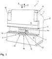
- a bending machine 1 has a machine base unit 2 the machine base unit of a conventional press brake and also a processing unit 3.
- the machine base unit 2 includes a machine frame as usual 4 and a pressing bar 5.
- the machine frame 4 forms a Support table 6 with a lower tool holder 7 off.
- the press beam 5 is on the machine frame 4 in a stroke direction 8 and guided in a return stroke 9 movable.
- To drive the press beam 5 serve hydraulic piston-cylinder assemblies 10. At its pointing to the support table 6 out Side is the press beam 5 with an upper tool holder 11 provided.
- the lower tool holder 7 and the upper tool holder 11 can conventional lower and upper tools of press brakes to be built in.
- the Processing unit 3 which is shown in FIG. 1 from a total four bending tools 12 is composed.
- the bending tools 12 are indicated along a dot-dash line in Fig. 1 Bend line 13 lined up without gaps.
- Each of the bending tools 12 comprises an upper tool in shape a hold-down 14 and a lower tool 15, which in turn a tool base 16 and an upper part 17 has.
- the Hold-down 14 of the bending tools 12 are in the upper tool holder 11 of the press bar 5, the lower tools 15 in the lower tool holder 7 of the support table 6 stored.
- the hold-down 14 of a bending tool 12 runs with an overhang to the vertical.
- a fastening lug 18 with which he in the upper tool holder 11 held on the pressing bar 5 of the bending machine 1 is.
- the toolholder is down 14 provided with a contact surface 19.
- the contact surface 19 goes into a side surface of the hold-down 14 over.
- each bending tool 12 rests with the tool base 16 on the support table 6 on the machine frame 4 of the bending machine 1.
- the tool base engages behind 16 the support table 6 laterally with a retaining projection 22.
- the nose 21 By means of the nose 21, the tool base 16 in the clamped lower tool holder 7.
- a bending member supported in the form of a pivot lever 23.
- a bearing block is used 24, on which the pivot lever 23 to one of a Achszapfen 25 formed pivot axis 26 pivotally mounted is.
- the bearing block 24 in turn is on the tool base 16 held pivotable about a pivot axis 27.
- To execute Pivoting movements of the bearing block 24 about the pivot axis 27th serves a screw 28 for adjusting the position of the bearing block 24. In the respectively adjusted position the storage block becomes 24 fixed by means of a locking screw 29.
- the receptacle 39 for the gas spring 36 is located on the upper part 17 of the lower tool 15 below a groove 40.
- the groove 40th takes a support body 41 of a workpiece support 42 of the Tops 17 on. Manually operable fasteners 43 hold the support body 41 in the groove 40th
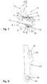
- the pivot lever 23 passes through the upper part 17 of the lower tool 15 at a penetration 44. Within the penetration 44 is the pivot lever 23 over a limited tilt angle pivotable about the pivot axis 26 and thereby in Hubquerides, i.e. perpendicular to the plane movable from the direction the bending line 13 and the stroke direction 8 and the remindhubides 9 is stretched. Formed on the pivot lever 23 is designed as a gate 46 control. The scenery 46 on the pivot lever 23 is on the upper part 17 of the lower tool 15 also serving as a control link guide assigned, in turn, from a control roller 47 and a control pin 50 is formed.
- the control roller 47 is rotatable about a rotation axis 48 at a Base body 49 of the upper part 17 stored. On the main body 49 of the upper part 17 and the control pin 50 is mounted, the engages in a guide slot 51 on the pivot lever 23. In an enlarged view, the constructive details of Swing lever 23 Fig. 8 can be seen.
- the pressing bar 5 faces raised to the support table 6 of the bending machine 1 so far that is between the free end of the press beam 5 mounted hold 14 and the top 17 of the Lower tool 15, in detail the workpiece support 42, a Gap results. In this space is the flat sheet 52. The insertion depth determines the later position the bend.
- the flat plate 52 is on the workpiece support 42nd stored.
- the bent plate 52 can now be removed from the bending tool 12.
- the fasteners 43 are to be solved by means of which the support body 41 of the workpiece support 42 in the groove 40th is fixed. Is then the support body 41 from the groove 40 removed, so is the attachment of the gas spring 36 at the upper part 17 accessible. After loosening this attachment can the upper part 17 removed as a unit from the tool base 16 become. The control pin 50 on the upper part 17 can thereby through the mouth lying in the direction of withdrawal from the guide slot 51 of the pivot lever 23 exit. Corresponding simply designed the assembly of the upper part 17 at the Tool base 16 of the lower tool 15th
- a changed backdrop geometry conditionally a change of with the concerned Swing lever realizable maximum bending angle. Furthermore can by using a backdrop with modified backdrop geometry an adaptation of the bending tool 12 to changed Sheet thicknesses and workpiece materials are made.
Landscapes
- Engineering & Computer Science (AREA)
- Mechanical Engineering (AREA)
- Bending Of Plates, Rods, And Pipes (AREA)
Priority Applications (4)
| Application Number | Priority Date | Filing Date | Title |
|---|---|---|---|
| AT04008272T ATE370806T1 (de) | 2004-04-06 | 2004-04-06 | Biegewerkzeug zum biegen von werkstücken, insbesondere von blechen sowie biegemaschine mit einem derartigen biegewerkzeug |
| EP04008272A EP1584385B1 (fr) | 2004-04-06 | 2004-04-06 | Outil de pliage pour des pièces, notamment tôles, ainsi que machine de pliage avec un tel outil de pliage |
| DE502004004723T DE502004004723D1 (de) | 2004-04-06 | 2004-04-06 | Biegewerkzeug zum Biegen von Werkstücken, insbesondere von Blechen sowie Biegemaschine mit einem derartigen Biegewerkzeug |
| US11/099,867 US7237419B2 (en) | 2004-04-06 | 2005-04-05 | Bending machine |
Applications Claiming Priority (1)
| Application Number | Priority Date | Filing Date | Title |
|---|---|---|---|
| EP04008272A EP1584385B1 (fr) | 2004-04-06 | 2004-04-06 | Outil de pliage pour des pièces, notamment tôles, ainsi que machine de pliage avec un tel outil de pliage |
Publications (2)
| Publication Number | Publication Date |
|---|---|
| EP1584385A1 true EP1584385A1 (fr) | 2005-10-12 |
| EP1584385B1 EP1584385B1 (fr) | 2007-08-22 |
Family
ID=34895990
Family Applications (1)
| Application Number | Title | Priority Date | Filing Date |
|---|---|---|---|
| EP04008272A Expired - Lifetime EP1584385B1 (fr) | 2004-04-06 | 2004-04-06 | Outil de pliage pour des pièces, notamment tôles, ainsi que machine de pliage avec un tel outil de pliage |
Country Status (4)
| Country | Link |
|---|---|
| US (1) | US7237419B2 (fr) |
| EP (1) | EP1584385B1 (fr) |
| AT (1) | ATE370806T1 (fr) |
| DE (1) | DE502004004723D1 (fr) |
Cited By (1)
| Publication number | Priority date | Publication date | Assignee | Title |
|---|---|---|---|---|
| WO2018055193A1 (fr) | 2016-09-26 | 2018-03-29 | Trumpf Werkzeugmaschinen Gmbh + Co. Kg | Outil, machine-outil et procédé d'usinage de pièces en forme de plaque |
Families Citing this family (3)
| Publication number | Priority date | Publication date | Assignee | Title |
|---|---|---|---|---|
| CN109262267B (zh) * | 2018-09-29 | 2023-07-28 | 青岛先楚能源发展集团有限公司 | 核电站换料水池水中折弯设备 |
| IT201900009657A1 (it) * | 2019-06-20 | 2020-12-20 | Dallan Spa | Macchina piegatrice per lamiere e metodo di piegatura di lamiere |
| CN112808804B (zh) * | 2019-11-18 | 2024-11-22 | 江苏畅通车业发展有限公司 | 一种外板件两端半圆耳折弯工装 |
Citations (4)
| Publication number | Priority date | Publication date | Assignee | Title |
|---|---|---|---|---|
| JPS5933032A (ja) * | 1982-08-16 | 1984-02-22 | Hitachi Ltd | 薄板の折り曲げ金型 |
| EP0610706A1 (fr) * | 1993-02-08 | 1994-08-17 | S.I.P.A. Societa Industrializzazione Progettazione E Automazione - S.P.A. | Amélioration dans une méthode de pliage des tôles et machine associée |
| WO1996024445A1 (fr) * | 1995-02-06 | 1996-08-15 | Amada Company, Ltd. | Machine a cintrer les toles |
| EP1250968A1 (fr) * | 2001-04-18 | 2002-10-23 | Umix Co., Ltd. | Appareil de pressage |
Family Cites Families (3)
| Publication number | Priority date | Publication date | Assignee | Title |
|---|---|---|---|---|
| FR2523483B1 (fr) * | 1982-03-19 | 1985-09-27 | Pauzin Alexis | Outil de pliage a plat |
| JPH05261441A (ja) * | 1992-03-17 | 1993-10-12 | Amada Co Ltd | 板材曲げ型装置 |
| JPH0631342A (ja) * | 1992-07-14 | 1994-02-08 | Amada Co Ltd | 板材曲げ型装置 |
-
2004
- 2004-04-06 EP EP04008272A patent/EP1584385B1/fr not_active Expired - Lifetime
- 2004-04-06 AT AT04008272T patent/ATE370806T1/de active
- 2004-04-06 DE DE502004004723T patent/DE502004004723D1/de not_active Expired - Lifetime
-
2005
- 2005-04-05 US US11/099,867 patent/US7237419B2/en not_active Expired - Lifetime
Patent Citations (4)
| Publication number | Priority date | Publication date | Assignee | Title |
|---|---|---|---|---|
| JPS5933032A (ja) * | 1982-08-16 | 1984-02-22 | Hitachi Ltd | 薄板の折り曲げ金型 |
| EP0610706A1 (fr) * | 1993-02-08 | 1994-08-17 | S.I.P.A. Societa Industrializzazione Progettazione E Automazione - S.P.A. | Amélioration dans une méthode de pliage des tôles et machine associée |
| WO1996024445A1 (fr) * | 1995-02-06 | 1996-08-15 | Amada Company, Ltd. | Machine a cintrer les toles |
| EP1250968A1 (fr) * | 2001-04-18 | 2002-10-23 | Umix Co., Ltd. | Appareil de pressage |
Non-Patent Citations (1)
| Title |
|---|
| PATENT ABSTRACTS OF JAPAN vol. 0081, no. 32 (M - 303) 20 June 1984 (1984-06-20) * |
Cited By (2)
| Publication number | Priority date | Publication date | Assignee | Title |
|---|---|---|---|---|
| WO2018055193A1 (fr) | 2016-09-26 | 2018-03-29 | Trumpf Werkzeugmaschinen Gmbh + Co. Kg | Outil, machine-outil et procédé d'usinage de pièces en forme de plaque |
| US11478835B2 (en) | 2016-09-26 | 2022-10-25 | Trumpf Werkzeugmaschinen Gmbh + Co. Kg | Machining planar workpieces |
Also Published As
| Publication number | Publication date |
|---|---|
| DE502004004723D1 (de) | 2007-10-04 |
| ATE370806T1 (de) | 2007-09-15 |
| US20050217342A1 (en) | 2005-10-06 |
| EP1584385B1 (fr) | 2007-08-22 |
| US7237419B2 (en) | 2007-07-03 |
Similar Documents
| Publication | Publication Date | Title |
|---|---|---|
| DE3610317C2 (fr) | ||
| DE69406545T2 (de) | Mechanische hand zum transportieren von platten, insbesondere metallplatten relativ zu einer werkzeugmaschine wie etwa einer abkantpresse | |
| DE69805631T2 (de) | Biegepresse für metallblech | |
| DE1910977B2 (de) | Schraubstockvorrichtung, insbesondere für tragbare werkbänke | |
| WO2012151601A1 (fr) | Installation de fabrication comportant un système de changement d'outil | |
| CH676945A5 (fr) | ||
| DE2915327C2 (de) | Arbeitsmaschine mit Fingerschutzeinrichtung für das bewegbare Oberwerkzeug | |
| DE3047348C2 (fr) | ||
| EP1674197B1 (fr) | Dispositif d'alimentation des panneaux | |
| EP1064109B1 (fr) | Cintreuse pour materiau plat | |
| DE19901794A1 (de) | Biegemaschine | |
| EP1584385A1 (fr) | Outil de pliage pour des pièces, notamment tôles, ainsi que machine de pliage avec un tel outil de pliage | |
| EP1748855B1 (fr) | Dispositif pour le deplacement pas a pas de pieces a usiner | |
| DE19529570A1 (de) | Werkstückanschlageinrichtung | |
| AT518255B1 (de) | Werkzeugwechselvorrichtung für eine Abkantpresse und Verfahren zum Durchführen eines Werkzeugwechsels | |
| EP0873206B1 (fr) | Plieuse | |
| EP1964797B1 (fr) | Dispositif de saisie, en particulier pince de serrage, destiné à l'utilisation dans un dispositif d'avancement pour outils en forme de plaques | |
| AT515407A4 (de) | Biegewerkzeug sowie Wechseleinheit hierfür | |
| DE4007590C2 (fr) | ||
| DE10102488A1 (de) | Vorrichtung zur Höheneinstellung einer Mehrzahl von Werkzeughaltern für eine Abkantpresse | |
| DE3809327A1 (de) | Stanze mit einem in der seitenansicht liegend u-foermigen maschinengestell | |
| DE4225836A1 (de) | Lochstanze | |
| EP3427853B1 (fr) | Unité de butée arrière ainsi qu'installation de fabrication équipée d'une telle unité de butée arrière | |
| DE20004498U1 (de) | Bördeleinheit | |
| DE7537486U (de) | Revolverstanzpresse |
Legal Events
| Date | Code | Title | Description |
|---|---|---|---|
| PUAI | Public reference made under article 153(3) epc to a published international application that has entered the european phase |
Free format text: ORIGINAL CODE: 0009012 |
|
| AK | Designated contracting states |
Kind code of ref document: A1 Designated state(s): AT BE BG CH CY CZ DE DK EE ES FI FR GB GR HU IE IT LI LU MC NL PL PT RO SE SI SK TR |
|
| AX | Request for extension of the european patent |
Extension state: AL HR LT LV MK |
|
| 17P | Request for examination filed |
Effective date: 20060329 |
|
| AKX | Designation fees paid |
Designated state(s): AT BE BG CH CY CZ DE DK EE ES FI FR GB GR HU IE IT LI LU MC NL PL PT RO SE SI SK TR |
|
| 17Q | First examination report despatched |
Effective date: 20060904 |
|
| 17Q | First examination report despatched |
Effective date: 20060904 |
|
| GRAP | Despatch of communication of intention to grant a patent |
Free format text: ORIGINAL CODE: EPIDOSNIGR1 |
|
| GRAS | Grant fee paid |
Free format text: ORIGINAL CODE: EPIDOSNIGR3 |
|
| GRAA | (expected) grant |
Free format text: ORIGINAL CODE: 0009210 |
|
| AK | Designated contracting states |
Kind code of ref document: B1 Designated state(s): AT BE BG CH CY CZ DE DK EE ES FI FR GB GR HU IE IT LI LU MC NL PL PT RO SE SI SK TR |
|
| REG | Reference to a national code |
Ref country code: GB Ref legal event code: FG4D Free format text: NOT ENGLISH |
|
| REG | Reference to a national code |
Ref country code: CH Ref legal event code: EP |
|
| REG | Reference to a national code |
Ref country code: IE Ref legal event code: FG4D Free format text: LANGUAGE OF EP DOCUMENT: GERMAN |
|
| REF | Corresponds to: |
Ref document number: 502004004723 Country of ref document: DE Date of ref document: 20071004 Kind code of ref document: P |
|
| GBT | Gb: translation of ep patent filed (gb section 77(6)(a)/1977) |
Effective date: 20071126 |
|
| PG25 | Lapsed in a contracting state [announced via postgrant information from national office to epo] |
Ref country code: ES Free format text: LAPSE BECAUSE OF FAILURE TO SUBMIT A TRANSLATION OF THE DESCRIPTION OR TO PAY THE FEE WITHIN THE PRESCRIBED TIME-LIMIT Effective date: 20071203 Ref country code: BG Free format text: LAPSE BECAUSE OF FAILURE TO SUBMIT A TRANSLATION OF THE DESCRIPTION OR TO PAY THE FEE WITHIN THE PRESCRIBED TIME-LIMIT Effective date: 20071122 Ref country code: FI Free format text: LAPSE BECAUSE OF FAILURE TO SUBMIT A TRANSLATION OF THE DESCRIPTION OR TO PAY THE FEE WITHIN THE PRESCRIBED TIME-LIMIT Effective date: 20070822 |
|
| PG25 | Lapsed in a contracting state [announced via postgrant information from national office to epo] |
Ref country code: PL Free format text: LAPSE BECAUSE OF FAILURE TO SUBMIT A TRANSLATION OF THE DESCRIPTION OR TO PAY THE FEE WITHIN THE PRESCRIBED TIME-LIMIT Effective date: 20070822 |
|
| ET | Fr: translation filed | ||
| REG | Reference to a national code |
Ref country code: IE Ref legal event code: FD4D |
|
| PG25 | Lapsed in a contracting state [announced via postgrant information from national office to epo] |
Ref country code: GR Free format text: LAPSE BECAUSE OF FAILURE TO SUBMIT A TRANSLATION OF THE DESCRIPTION OR TO PAY THE FEE WITHIN THE PRESCRIBED TIME-LIMIT Effective date: 20071123 Ref country code: DK Free format text: LAPSE BECAUSE OF FAILURE TO SUBMIT A TRANSLATION OF THE DESCRIPTION OR TO PAY THE FEE WITHIN THE PRESCRIBED TIME-LIMIT Effective date: 20070822 |
|
| PG25 | Lapsed in a contracting state [announced via postgrant information from national office to epo] |
Ref country code: SK Free format text: LAPSE BECAUSE OF FAILURE TO SUBMIT A TRANSLATION OF THE DESCRIPTION OR TO PAY THE FEE WITHIN THE PRESCRIBED TIME-LIMIT Effective date: 20070822 Ref country code: CZ Free format text: LAPSE BECAUSE OF FAILURE TO SUBMIT A TRANSLATION OF THE DESCRIPTION OR TO PAY THE FEE WITHIN THE PRESCRIBED TIME-LIMIT Effective date: 20070822 Ref country code: PT Free format text: LAPSE BECAUSE OF FAILURE TO SUBMIT A TRANSLATION OF THE DESCRIPTION OR TO PAY THE FEE WITHIN THE PRESCRIBED TIME-LIMIT Effective date: 20080122 Ref country code: IE Free format text: LAPSE BECAUSE OF FAILURE TO SUBMIT A TRANSLATION OF THE DESCRIPTION OR TO PAY THE FEE WITHIN THE PRESCRIBED TIME-LIMIT Effective date: 20070822 |
|
| PLBE | No opposition filed within time limit |
Free format text: ORIGINAL CODE: 0009261 |
|
| STAA | Information on the status of an ep patent application or granted ep patent |
Free format text: STATUS: NO OPPOSITION FILED WITHIN TIME LIMIT |
|
| PG25 | Lapsed in a contracting state [announced via postgrant information from national office to epo] |
Ref country code: SE Free format text: LAPSE BECAUSE OF FAILURE TO SUBMIT A TRANSLATION OF THE DESCRIPTION OR TO PAY THE FEE WITHIN THE PRESCRIBED TIME-LIMIT Effective date: 20071122 Ref country code: RO Free format text: LAPSE BECAUSE OF FAILURE TO SUBMIT A TRANSLATION OF THE DESCRIPTION OR TO PAY THE FEE WITHIN THE PRESCRIBED TIME-LIMIT Effective date: 20070822 |
|
| 26N | No opposition filed |
Effective date: 20080526 |
|
| PG25 | Lapsed in a contracting state [announced via postgrant information from national office to epo] |
Ref country code: MC Free format text: LAPSE BECAUSE OF NON-PAYMENT OF DUE FEES Effective date: 20080430 |
|
| PG25 | Lapsed in a contracting state [announced via postgrant information from national office to epo] |
Ref country code: EE Free format text: LAPSE BECAUSE OF FAILURE TO SUBMIT A TRANSLATION OF THE DESCRIPTION OR TO PAY THE FEE WITHIN THE PRESCRIBED TIME-LIMIT Effective date: 20070822 |
|
| PG25 | Lapsed in a contracting state [announced via postgrant information from national office to epo] |
Ref country code: SI Free format text: LAPSE BECAUSE OF FAILURE TO SUBMIT A TRANSLATION OF THE DESCRIPTION OR TO PAY THE FEE WITHIN THE PRESCRIBED TIME-LIMIT Effective date: 20070822 |
|
| PG25 | Lapsed in a contracting state [announced via postgrant information from national office to epo] |
Ref country code: CY Free format text: LAPSE BECAUSE OF FAILURE TO SUBMIT A TRANSLATION OF THE DESCRIPTION OR TO PAY THE FEE WITHIN THE PRESCRIBED TIME-LIMIT Effective date: 20070822 |
|
| PGFP | Annual fee paid to national office [announced via postgrant information from national office to epo] |
Ref country code: BE Payment date: 20090429 Year of fee payment: 6 |
|
| PGFP | Annual fee paid to national office [announced via postgrant information from national office to epo] |
Ref country code: GB Payment date: 20090424 Year of fee payment: 6 |
|
| PG25 | Lapsed in a contracting state [announced via postgrant information from national office to epo] |
Ref country code: HU Free format text: LAPSE BECAUSE OF FAILURE TO SUBMIT A TRANSLATION OF THE DESCRIPTION OR TO PAY THE FEE WITHIN THE PRESCRIBED TIME-LIMIT Effective date: 20080223 Ref country code: LU Free format text: LAPSE BECAUSE OF NON-PAYMENT OF DUE FEES Effective date: 20080406 |
|
| PG25 | Lapsed in a contracting state [announced via postgrant information from national office to epo] |
Ref country code: TR Free format text: LAPSE BECAUSE OF FAILURE TO SUBMIT A TRANSLATION OF THE DESCRIPTION OR TO PAY THE FEE WITHIN THE PRESCRIBED TIME-LIMIT Effective date: 20070822 |
|
| BERE | Be: lapsed |
Owner name: TRUMPF MASCHINEN AUSTRIA GMBH & CO. KG. Effective date: 20100430 |
|
| GBPC | Gb: european patent ceased through non-payment of renewal fee |
Effective date: 20100406 |
|
| PG25 | Lapsed in a contracting state [announced via postgrant information from national office to epo] |
Ref country code: BE Free format text: LAPSE BECAUSE OF NON-PAYMENT OF DUE FEES Effective date: 20100430 Ref country code: GB Free format text: LAPSE BECAUSE OF NON-PAYMENT OF DUE FEES Effective date: 20100406 |
|
| REG | Reference to a national code |
Ref country code: FR Ref legal event code: PLFP Year of fee payment: 12 |
|
| PGFP | Annual fee paid to national office [announced via postgrant information from national office to epo] |
Ref country code: NL Payment date: 20150422 Year of fee payment: 12 |
|
| PGFP | Annual fee paid to national office [announced via postgrant information from national office to epo] |
Ref country code: CH Payment date: 20150422 Year of fee payment: 12 |
|
| PGFP | Annual fee paid to national office [announced via postgrant information from national office to epo] |
Ref country code: IT Payment date: 20150427 Year of fee payment: 12 Ref country code: FR Payment date: 20150422 Year of fee payment: 12 |
|
| REG | Reference to a national code |
Ref country code: CH Ref legal event code: PL |
|
| REG | Reference to a national code |
Ref country code: NL Ref legal event code: MM Effective date: 20160501 |
|
| REG | Reference to a national code |
Ref country code: FR Ref legal event code: ST Effective date: 20161230 |
|
| PG25 | Lapsed in a contracting state [announced via postgrant information from national office to epo] |
Ref country code: NL Free format text: LAPSE BECAUSE OF NON-PAYMENT OF DUE FEES Effective date: 20160501 Ref country code: LI Free format text: LAPSE BECAUSE OF NON-PAYMENT OF DUE FEES Effective date: 20160430 Ref country code: CH Free format text: LAPSE BECAUSE OF NON-PAYMENT OF DUE FEES Effective date: 20160430 Ref country code: FR Free format text: LAPSE BECAUSE OF NON-PAYMENT OF DUE FEES Effective date: 20160502 |
|
| PG25 | Lapsed in a contracting state [announced via postgrant information from national office to epo] |
Ref country code: IT Free format text: LAPSE BECAUSE OF NON-PAYMENT OF DUE FEES Effective date: 20160406 |
|
| PGFP | Annual fee paid to national office [announced via postgrant information from national office to epo] |
Ref country code: DE Payment date: 20230420 Year of fee payment: 20 |
|
| PGFP | Annual fee paid to national office [announced via postgrant information from national office to epo] |
Ref country code: AT Payment date: 20230420 Year of fee payment: 20 |
|
| REG | Reference to a national code |
Ref country code: DE Ref legal event code: R071 Ref document number: 502004004723 Country of ref document: DE |
|
| REG | Reference to a national code |
Ref country code: AT Ref legal event code: MK07 Ref document number: 370806 Country of ref document: AT Kind code of ref document: T Effective date: 20240406 |