EP1584410A2 - Schleif- und Konturierverfahren der Gleitfläche eines Gleitelementes von einem Schlittschuh und Vorrichtung zur Anwendung dieses Verfahrens - Google Patents
Schleif- und Konturierverfahren der Gleitfläche eines Gleitelementes von einem Schlittschuh und Vorrichtung zur Anwendung dieses Verfahrens Download PDFInfo
- Publication number
- EP1584410A2 EP1584410A2 EP05075198A EP05075198A EP1584410A2 EP 1584410 A2 EP1584410 A2 EP 1584410A2 EP 05075198 A EP05075198 A EP 05075198A EP 05075198 A EP05075198 A EP 05075198A EP 1584410 A2 EP1584410 A2 EP 1584410A2
- Authority
- EP
- European Patent Office
- Prior art keywords
- grinding
- sliding surface
- template
- sliding
- positioning member
- Prior art date
- Legal status (The legal status is an assumption and is not a legal conclusion. Google has not performed a legal analysis and makes no representation as to the accuracy of the status listed.)
- Withdrawn
Links
- 238000000034 method Methods 0.000 title claims abstract description 33
- 125000006850 spacer group Chemical group 0.000 description 5
- 239000000463 material Substances 0.000 description 3
- XAGFODPZIPBFFR-UHFFFAOYSA-N aluminium Chemical compound [Al] XAGFODPZIPBFFR-UHFFFAOYSA-N 0.000 description 1
- 229910052782 aluminium Inorganic materials 0.000 description 1
- 239000004411 aluminium Substances 0.000 description 1
- 230000002452 interceptive effect Effects 0.000 description 1
Images


Classifications
-
- B—PERFORMING OPERATIONS; TRANSPORTING
- B24—GRINDING; POLISHING
- B24B—MACHINES, DEVICES, OR PROCESSES FOR GRINDING OR POLISHING; DRESSING OR CONDITIONING OF ABRADING SURFACES; FEEDING OF GRINDING, POLISHING, OR LAPPING AGENTS
- B24B3/00—Sharpening cutting edges, e.g. of tools; Accessories therefor, e.g. for holding the tools
- B24B3/003—Sharpening cutting edges, e.g. of tools; Accessories therefor, e.g. for holding the tools for skate blades
Definitions
- the present invention pertains to a method for grinding and contouring a sliding surface of a sliding element of an ice-skate applying a grinding device having a grinding element, and a template with a reference profile, the method comprising fixating the template with respect to the sliding surface and moving the grinding element with respect to the sliding surface while grinding this surface, during which moving the grinding element follows the reference profile of the template.
- the invention also pertains to a device which is devised for applying the said method.
- the above-described method is known from United States patent 5,897,428.
- a grinding device is being used having a fixture for positioning and holding the ice skate and a template.
- the method starts off with clamping the skate into the fixture, and then moving a grinding wheel to the fixture.
- the sliding surface of the sliding element of the ice skate is grinded while the fixture follows a reference profile of the template.
- the fixture in the known device has clamping plates for clamping the sliding element, i.e. the ice skate blade.
- the fixture slides along the top surface of a table with the fixture being movable into and away from the grinding wheel.
- the position of the fixture is adjusted with respect to the grinding wheel. This way, the sliding surface can be grinded and contoured in one step with high accuracy.
- the sliding surface is whetted after grinding and contouring.
- a grinding method of this kind is also known from Dutch patent 1014647, namely clamping the sliding element of an ice skate in a fixture of a grinding device, and moving the clamped skate with respect to a grinding wheel while the clamped skate follows the reference profile of a template.
- the purpose of the present invention is to mitigate all the above-described disadvantages.
- a method has been devised using a positioning member, the method comprising positioning the template against the positioning member, then positioning the sliding surface against the same positioning member, where-after the template is fixated with respect to the sliding surface.
- the grinding element is moved with respect to the sliding surface while grinding and contouring this surface, during which moving the reference profile of the template is followed.
- This method is based on the recognition that for accurate grinding while at the same time removing as less material as possible, the to-be-grinded-surface, i.e. the sliding surface of the sliding element of the ice skate, needs to be accurately positioned with respect to the template.
- the skate is clamped at its sliding element in the fixture of the grinding device, and then, the position of the fixture or the skate is adjusted such that the sliding surface gets the appropriate position.
- the present invention by making use of the same positioning member against which both the sliding surface and the template are positioned, a very simple method has been invented for accurately positioning these elements with respect to each other. It is no longer necessary to adjust the position of the skate itself with respect to the template since the relevant part of the skate, i.e.
- the sliding surface of the skate is already highly accurately positioned merely by using the same positioning member against which the template is also placed.
- typical amounts in the order of tens of micrometers are grinded away to get a very good grinding and contouring result.
- An additional advantage of the method according to the present invention appears to be that the device itself can be made fairly compact without losing its accuracy. This is also a very important feature because this way it becomes readily possible to take along the grinding device to a speed skating match.
- the template is positioned against the positioning member such that the reference profile is in abutting relationship with the said positioning member.
- This embodiment has the advantage that the template needs only to be made with accurate dimensions where pertaining to the reference profile itself. The other sides can be made which less accuracy, thus contributing to a more simple method and less expensive device.
- the sliding surface as well as the reference profile are in abutting relationship with the positioning member, a higher accuracy of contouring can be achieved while grinding away even less material. This is due to the fact that the two surfaces that need to be brought in agreement, i.e. the sliding surface and the reference profile, can be positioned in nearly perfect relationship with almost no spacial tolerances interfering in the said relationship.
- the sliding surface and the template are positioned against the same side of the positioning member.
- the positioning of both elements can be more accurate even though the procedure of positioning takes minor effort and skill. Also, as an additional advantage it appears that this way a more compact device can be devised, thus contributing to an important advantage of the invention in its widest scope.
- an intermediate element is placed between the sliding element and template abutting both the sliding element and template.
- an elongate intermediate element can be used which is sandwiched between the template and the sliding element of the ice skate, which latter mentioned elements are essentially in parallel with this intermediate element.
- the positioning member comprises the grinding element.
- the grinding element is part of the positioning member. This embodiment has the advantage that there is no need for using an additional positioning element for positioning the sliding surface of the ice skate and/or the template against. In this embodiment the sliding surface of the ice skate as well as the template can be positioned directly against the grinding element (being part of the positioning member).
- the stop element is removably connected to the positioning member, the stop element is removed after fixating the template with respect to the sliding surface, at least where this stop element was previously abutting the sliding surface.
- This embodiment provides for a method wherein each part of the sliding surface can be grinded and contoured in one grinding step.
- the sliding surface and template are positioned against these sub-elements.
- This embodiment appears to be of particular advantage when a contour has to be given to the sliding surface that is substantially equal to the arc of a circle. In ice skating, in particular speed skating, this arc has to be grinded into the sliding element with the highest possible accuracy. Typical radii of these arcs are 5 - 15 metres for short track skating and 15 - 35 metres for speed skating.
- the two sub-elements can for example be placed at a distance which is substantially equal to a little bit less than the length of the sliding surface of the ice skate. This way, when abutting the curved sliding surface and reference profile against the two sub-elements, an immediate and good agreement of both the respective arcs is provided for without the need of any additional adjusting step.
- the sliding element and the template are laterally positioned against another stop element.
- This embodiment is of particular advantage for example when a contour has to be brought into the sliding surface that does not equal the arc of a circle, for example because it is composed of two or more arcs, or an arc and a straight part, etc.
- lateral positioning of the template and sliding surface with respect to each other is conveniently provided for when a lateral stop element is used against which both elements can be placed.
- the present invention is also directed to the device for grinding and contouring the sliding surface of the sliding element of the ice skate, wherein the device comprises placing means for positioning the sliding surface and the template against the stop element.
- the placing means are such that the template is positioned against the stop element with the reference profile in abutting relationship with this stop element.
- the placing means are such that the sliding surface and the template are positioned against the same side of the stop element.
- Figure 1 represents a front view of a part of the grinding device.
- the device is placed on base 1, which in this case is an aluminium profile.
- base 1 On this base 1 a positioning member is placed, which member is constituted by supporting parts 21 a and 21 b and a stop element, which element in this particular embodiment consists of two separate sub-elements 2a and 2b. These sub-elements are removably connected to the supporting parts 21 a and 21 b by use of bolts 13 and 12 respectively.
- front faces 20a and 20b of these stop sub-elements are shown, located at reference locations x and y respectively.
- Placed on top of the supporting elements 21 a and 21 b is template 3, of which in this view reference profile 30 is shown.
- template 3 Placed on top of template 3 is intermediate element 4.
- This element carries the sliding element 5 of the ice skate, of which sliding element sliding surface 50 and a small part of the ice skate shoe 7 is shown in this front view.
- Placed on top of the sliding element 5 is elongate element 6. Template and sliding surface are fixated with relative to one another by clamping the elements 3, 4, 5 and 6 together, by applying screws 10 and 11.
- Figure 2 is a side view of the device as depicted in figure 1.
- the stop element 2a is connected to supporting member 21 a by using bolt 13.
- stop element 2b is connected to supporting element 21 b by using bolt 12. This way, the positioning member is provided for.
- template 3 is placed onto the supporting members 21 a and 21 b, whereby the reference profile 30 is positioned against the stop sub-elements 2a and 2b.
- intermediate element 4 is placed on top of the template (in an alternative embodiment, element 4 is formed integrally with template 3).
- the ice skate is placed with its sliding element on top of the intermediate element 4, such that the sliding surface 50 is positioned against the stop sub-elements.
- the stop sub-elements are profiled in order to provide for a shift in horizontal direction between the sliding surface and the reference profile.
- elongate element 6 is placed (in an alternative embodiment element 6 is formed integrally with part 221). For clamping all elements together, two clamping pieces, of which only piece 221 is shown in this side view, are placed on the supporting elements 21 a and 21 b respectively.
- this embodiment there is a small gap between element 221 and element 5 in order to prevent distortion of the stop element 2a with respect to the sliding element 5 and template 3.
- this pieces force the collection of elements 3, 4, 5 and 6 down onto supporting elements 21 a and 21 b.
- these elements are positioned again against stop sub-elements 2a and 2b, to ensure a proper and adequate relationship between the reference profile of the template and the sliding surface of the sliding element of the ice skate.
- FIG 3 is a side view of the device including the grinding element.
- the grinding element consists in this embodiment of various parts of which some can be seen in this side view.
- the grinding element has a base part 104 which is slidably carried by base 1 of the grinding device. Connected to the base part 104 via carrying part 103 is drive motor 102. To this motor is rotatably connected a cup grinding wheel 100 via shaft 101. Cup wheel 100 is positioned against the sliding surface 50 of the sliding element 5 of the ice skate. In order to properly contour the sliding surface, the grinding element is in slidable connection with reference profile 30. For this, spacer elements are used of which element 111 is shown. This element ends with a small guiding wheel 110 which is able to rotate while following reference profile 30.
- adjustment screws are comprised in the spacer elements.
- element 111 adjustment screw 112 is shown.
- the grinding element is used as the positioning member.
- the grinding element is moved to one side of the grinding device, e.g. near reference location x (see figure 1). Then the first end of the template (in this embodiment formed integrally with element 4) is abutted against the guiding wheel 110. After this, the ice skate is put on top of element 4 and the sliding surface of the skate is positioned against the grinding wheel 100.
- these elements are fixed with respect to each other (at least, at their ends corresponding to the first side of the grinding device) as indicated here-above, but in a way that rotation of both elements about a vertical axis at reference location x is still possible.
- the grinding element is moved to the second side of the device near location y (see figure 1).
- the other end of the template is positioned against the guiding wheel, and the corresponding side of the sliding surface is positioned against the grinding wheel (while doing this both elements, if needed, rotate about the mentioned axis).
- these other ends of the template and sliding surface are fixed with respect to each other.
- a final check can be made (after moving the grinding element back to the first side of the grinding device) whether or not the firstly positioned ends of the template and sliding surface are still in good spacial relation with respect to each other.
- the sliding surface of the ice skate and the template are brought in perfect aligned with each other and the grinding wheel, without the need of an additional positioning member next to the grinding element itself.
- the adjustment screws (element 112 and its equivalent at the other side of the grinding element) can be used to move the grinding wheel in the direction of the sliding surface.
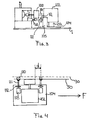
- FIG 4 is a top view of the main parts of he device according to figure 3. Schematically shown are sliding surface 50 and the shifted reference profile 30 of the template, which latter element is shown in dashed line. It can be seen that the grinding element is positioned against the reference profile by use of two spacer elements that abut the profile with respective wheels. By adjusting the effective length of the spacer elements by applying the adjustment screws, the grinding element is properly positioned with respect to the sliding surface 50 of the sliding element of the ice skate. In this embodiment the grinding wheel 100 is slightly tilted with respect to the sliding surface such that grinding takes place essentially at the single point of contact between the cup wheel 100 and the sliding surface.
- the distance between the small wheel abutting the reference profile of the template and the said point of contact is denoted as "d" in figure 4.
- the grinding element is shifted in the direction denoted F in figure 4, while properly engaging the reference profile with its wheels at the end of the spacer elements. This way, the grinding element follows the reference profile of template 3 while grinding the sliding surface of the ice skate. This means that at the same time, the sliding surface attains a contour that is equal to the contour of the reference profile 30. It needed, the grinding element can be shifted backwards to grind the sliding surface a second time.
- Figure 5 is a schematic drawing showing the lateral relationship of the reference profile and sliding surface when positioned in the device according to figure 1.
- the curvature of both surfaces is extremely exaggerated in this figure.
- the sliding surface 50 and the reference profile 30 are slightly shifted with respect to each other in order to compensate for the distance "d" as depicted in figure 5.
- This provides for better grinding and contouring.
- the small shift can be introduced by providing corresponding profiles in the surface of the stop sub-elements against which the sliding surface and reference profile are positioned.
- the shift as depicted in figure 5 compensates for a grinding element that is tilted such that the other end (near wheel 110) of the cup wheel is positioned against the sliding surface.
- a grinding wheel would be used of which its point of contact would be right in the middle between the two small supporting wheels that contact the reference profile 30, essentially the same grinding and contouring result can be provided for without compensating for the distance "d".
- the device may be constructed in order to grind two sliding surfaces of two separate ice skates at a time.
- contours that differ substantially from a single curved arc may be advantageously grinded into ice skates using the method and device according to the present invention.
- Templates can be used having two or more reference profiles such that one template can be used to grind different radii in sliding surfaces.
- Other types of grinding wheels than the exemplified cup wheel, or other orientations of the grinding wheel with respect to the sliding surface can also be successfully applied in the method and device according to the present invention.
Landscapes
- Engineering & Computer Science (AREA)
- Mechanical Engineering (AREA)
- Grinding And Polishing Of Tertiary Curved Surfaces And Surfaces With Complex Shapes (AREA)
Priority Applications (1)
| Application Number | Priority Date | Filing Date | Title |
|---|---|---|---|
| EP05075198A EP1584410A3 (de) | 2004-01-29 | 2005-01-26 | Schleif- und Konturierverfahren der Gleitfläche eines Gleitelementes von einem Schlittschuh und Vorrichtung zur Anwendung dieses Verfahrens |
Applications Claiming Priority (3)
| Application Number | Priority Date | Filing Date | Title |
|---|---|---|---|
| EP04075302 | 2004-01-29 | ||
| EP04075302 | 2004-01-29 | ||
| EP05075198A EP1584410A3 (de) | 2004-01-29 | 2005-01-26 | Schleif- und Konturierverfahren der Gleitfläche eines Gleitelementes von einem Schlittschuh und Vorrichtung zur Anwendung dieses Verfahrens |
Publications (2)
| Publication Number | Publication Date |
|---|---|
| EP1584410A2 true EP1584410A2 (de) | 2005-10-12 |
| EP1584410A3 EP1584410A3 (de) | 2006-03-08 |
Family
ID=34913487
Family Applications (1)
| Application Number | Title | Priority Date | Filing Date |
|---|---|---|---|
| EP05075198A Withdrawn EP1584410A3 (de) | 2004-01-29 | 2005-01-26 | Schleif- und Konturierverfahren der Gleitfläche eines Gleitelementes von einem Schlittschuh und Vorrichtung zur Anwendung dieses Verfahrens |
Country Status (1)
| Country | Link |
|---|---|
| EP (1) | EP1584410A3 (de) |
Cited By (3)
| Publication number | Priority date | Publication date | Assignee | Title |
|---|---|---|---|---|
| SE545052C2 (en) * | 2019-09-11 | 2023-03-14 | Prosharp Inc | Method for profiling blades with a belt grinding profiling machine |
| US11806826B2 (en) | 2019-09-11 | 2023-11-07 | Prosharp Inc. | Automatic blade holder |
| US12179087B2 (en) | 2013-03-11 | 2024-12-31 | Bauer Hockey Llc | Skate with injected boot form |
Family Cites Families (4)
| Publication number | Priority date | Publication date | Assignee | Title |
|---|---|---|---|---|
| US1487142A (en) * | 1922-04-05 | 1924-03-18 | Vitus A Boker | Skate-grinding machine |
| GB608207A (en) * | 1946-02-18 | 1948-09-10 | Peter Macpherson Forrester | Improvements in or relating to grinding ice-skates |
| CA920819A (en) * | 1971-02-12 | 1973-02-13 | Merco International Ltd. | Sharpening of ice skates |
| US4109419A (en) * | 1977-01-12 | 1978-08-29 | Sidney Broadbent | Ice skate sharpening devices |
-
2005
- 2005-01-26 EP EP05075198A patent/EP1584410A3/de not_active Withdrawn
Cited By (5)
| Publication number | Priority date | Publication date | Assignee | Title |
|---|---|---|---|---|
| US12179087B2 (en) | 2013-03-11 | 2024-12-31 | Bauer Hockey Llc | Skate with injected boot form |
| SE545052C2 (en) * | 2019-09-11 | 2023-03-14 | Prosharp Inc | Method for profiling blades with a belt grinding profiling machine |
| US11806826B2 (en) | 2019-09-11 | 2023-11-07 | Prosharp Inc. | Automatic blade holder |
| US11878386B2 (en) | 2019-09-11 | 2024-01-23 | Prosharp Inc. | Automatic blade holder |
| US12168279B2 (en) | 2019-09-11 | 2024-12-17 | Bauer Hockey Ltd. | Skate blade and apparatus for removing material from a skate blade |
Also Published As
| Publication number | Publication date |
|---|---|
| EP1584410A3 (de) | 2006-03-08 |
Similar Documents
| Publication | Publication Date | Title |
|---|---|---|
| US20240042568A1 (en) | Automatic blade holder | |
| CA2317807C (en) | Sharpening a knife blade | |
| AU2004230315B2 (en) | Honing guide assembly | |
| US7473164B2 (en) | Self-centering skate holder | |
| US20070281594A1 (en) | Honing guide assembly with camber roller | |
| US7281969B2 (en) | Tool sharpening and compound honing jig | |
| US6851345B1 (en) | Cutting table fence | |
| JP2011045971A (ja) | アイススケート靴用刃研磨装置 | |
| CA2260531A1 (en) | Device for bringing object to be sharpened into contact with grinding wheel | |
| US4346536A (en) | Tilting arbor belt sander | |
| WO2000067949A1 (en) | Blade sharpening | |
| CA3154282A1 (en) | Automatic blade holder | |
| EP0384093A1 (de) | Flach-Schleifmaschine mit festem Tisch | |
| US4501091A (en) | Apparatus for preparing an optical workpiece | |
| US6257962B1 (en) | Apparatus and methods for forming hollow-ground knife blades | |
| US5643066A (en) | Fixture for ski edge finishing tool | |
| US5097631A (en) | Circular edger attachment for vertical glass edger | |
| KR20080041343A (ko) | 스케이트 날 가공기 | |
| CN209453271U (zh) | 一种3d地板的去毛刺装置 | |
| US12481250B1 (en) | Watch refurbishing devices and methods | |
| CN220839508U (zh) | 一种金属支架加工用双面抛光装置 | |
| CN220005521U (zh) | 一种铜管弯管加工辅助装置 | |
| CN214869504U (zh) | 电动坡口机对口定位平台 | |
| CN219341146U (zh) | 一种可以自动微调定中的胶料导向装置 | |
| CN218017880U (zh) | 一种电缆磨片机 |
Legal Events
| Date | Code | Title | Description |
|---|---|---|---|
| PUAI | Public reference made under article 153(3) epc to a published international application that has entered the european phase |
Free format text: ORIGINAL CODE: 0009012 |
|
| AK | Designated contracting states |
Kind code of ref document: A2 Designated state(s): AT BE BG CH CY CZ DE DK EE ES FI FR GB GR HU IE IS IT LI LT LU MC NL PL PT RO SE SI SK TR |
|
| AX | Request for extension of the european patent |
Extension state: AL BA HR LV MK YU |
|
| PUAL | Search report despatched |
Free format text: ORIGINAL CODE: 0009013 |
|
| AK | Designated contracting states |
Kind code of ref document: A3 Designated state(s): AT BE BG CH CY CZ DE DK EE ES FI FR GB GR HU IE IS IT LI LT LU MC NL PL PT RO SE SI SK TR |
|
| AX | Request for extension of the european patent |
Extension state: AL BA HR LV MK YU |
|
| 17P | Request for examination filed |
Effective date: 20060828 |
|
| AKX | Designation fees paid |
Designated state(s): DE IT NL |
|
| STAA | Information on the status of an ep patent application or granted ep patent |
Free format text: STATUS: THE APPLICATION HAS BEEN WITHDRAWN |
|
| 18W | Application withdrawn |
Effective date: 20080617 |