EP1584536A2 - Kraftmessvorrichtung zur Erfassung der Schienenbelastung - Google Patents
Kraftmessvorrichtung zur Erfassung der Schienenbelastung Download PDFInfo
- Publication number
- EP1584536A2 EP1584536A2 EP05007521A EP05007521A EP1584536A2 EP 1584536 A2 EP1584536 A2 EP 1584536A2 EP 05007521 A EP05007521 A EP 05007521A EP 05007521 A EP05007521 A EP 05007521A EP 1584536 A2 EP1584536 A2 EP 1584536A2
- Authority
- EP
- European Patent Office
- Prior art keywords
- force
- rail
- measuring device
- threshold
- force measuring
- Prior art date
- Legal status (The legal status is an assumption and is not a legal conclusion. Google has not performed a legal analysis and makes no representation as to the accuracy of the status listed.)
- Granted
Links
Images

Classifications
-
- B—PERFORMING OPERATIONS; TRANSPORTING
- B61—RAILWAYS
- B61K—AUXILIARY EQUIPMENT SPECIALLY ADAPTED FOR RAILWAYS, NOT OTHERWISE PROVIDED FOR
- B61K9/00—Railway vehicle profile gauges; Detecting or indicating overheating of components; Apparatus on locomotives or cars to indicate bad track sections; General design of track recording vehicles
- B61K9/12—Measuring or surveying wheel-rims
-
- G—PHYSICS
- G01—MEASURING; TESTING
- G01G—WEIGHING
- G01G19/00—Weighing apparatus or methods adapted for special purposes not provided for in the preceding groups
- G01G19/02—Weighing apparatus or methods adapted for special purposes not provided for in the preceding groups for weighing wheeled or rolling bodies, e.g. vehicles
- G01G19/04—Weighing apparatus or methods adapted for special purposes not provided for in the preceding groups for weighing wheeled or rolling bodies, e.g. vehicles for weighing railway vehicles
- G01G19/045—Weighing apparatus or methods adapted for special purposes not provided for in the preceding groups for weighing wheeled or rolling bodies, e.g. vehicles for weighing railway vehicles for weighing railway vehicles in motion
- G01G19/047—Weighing apparatus or methods adapted for special purposes not provided for in the preceding groups for weighing wheeled or rolling bodies, e.g. vehicles for weighing railway vehicles for weighing railway vehicles in motion using electrical weight-sensitive devices
Definitions
- the invention relates to a force measuring device for detection the rail load, in particular by a rolling rail vehicle wheel, according to the preamble of claim 1.
- EP 0 500 971 A1 discloses a dynamic weighing method for railway vehicles are known, with which much of the rail load is traceable at the crossing rail traffic. To the shear stress is detected in the neutral phase of the rail and evaluated. For this purpose, in the Fahrschienennetz a Weighing rail applied with strain gages, welded at least two strain gauges between the sleepers are arranged. The wagon weight will be included determined by axlewise addition of the weight signals. With such a device but can the entire rail load can not be determined, in particular a secure flat-point detection is not possible, since this in the Range of thresholds can not be detected.
- a device for detecting unround wheels on railway vehicles is already known from DE 41 39 342 C1.
- this device are on a measuring section on the rail in the area of each threshold, two sensors on each side applied from strain gauges showing the threshold reaction forces to capture. Furthermore, there are thrust sensors provided in each case at the beginning and end of the measuring section in the neutral phase of the rail are arranged. With a but such device is obviously not accurate Weight load can be detected with rolling over vehicle wheels.
- From DE 198 34 030 A1 discloses a device for determining the weight load on the rail by traversing Track vehicles known. These are in the area of the threshold arranged parallel to each track two double bending beam, the are connected via lateral mounting plates with the rail. The connection between the rails and the two double bending beams takes place in each case before and after the threshold in so-called threshold compartment. In the middle, the double bending beams are supported each on the thresholds, so that on the rail acting vertical forces are detected with the Even out of roundness and flats are recognizable. Indeed requires secure flat or runout detection the detection on at least one wheel revolution of about 3.5 m Measuring section, including at standard thresholds at least 28 Force transducers are necessary. Since it is the two Force transducers with special high-precision double-sided double bending beams is, is for a rail load device with flat detection a high expenditure on equipment necessary.
- EP 1 212 228 B1 is a special device for Determination of non-circularities and flat spots on rail-bound Vehicle wheels known.
- this device are for detecting the rail load when traveling over rail vehicle wheels special measuring thresholds provided in the Transducers are inserted transversely to the rail direction, on where the rails are supported.
- These load cells are in her force introduction part firmly with the rail and her Kraftaus effetsteil firmly connected to the threshold.
- Force application and force evacuation are force return elements provided the force in a bar-shaped Initiate expansion body.
- In the expansion body are two provided horizontal mutually facing recesses, which leave in their middle a membrane-like connecting wall, on the strain gauges in the form of shear force transducers are applied.
- shear force sensors are located centrally in the vertical direction under the rail and capture thereby only vertical wheel contact forces. With such Although device is a secure detection of larger Out-of-roundness and flatness detectable, but not necessarily a value for the total track load can be determined.
- a weighing device for rail vehicles in which transversely arranged force transducers are provided between the rail and conventional sleepers.
- the load cells are attached to both the rail and the threshold.
- For force input and -aus ein two force return elements are provided, between which two bar-shaped deformation body are arranged.
- the deformation bodies are arranged symmetrically to a vertical center line to the rail center. Symmetrically and transversely in the beam-shaped deformation body, two recesses are provided against each other, between which a membrane-like connecting wall is left, on each of which the strain gauges are arranged in the form of Scherkraftaufêtn.
- force measuring devices are provided as a measuring path, at least along the length of a Rohmdrchung, with the slower crossing a very accurate determination of weight by detecting the vertical Radaufstands technology is possible.
- thrust loaders are still provided at the beginning and end of the measuring section in the neutral phase of the rail web, which determine the axial Kraftneben gleichkopplung during the crossing and mathematically considered in the weight determination.
- this device it is also provided at the same time to compare the vertical force signals of each force measuring device during the crossing with each other and to signal or display at a predetermined deviation as out-of-roundness or flat.
- the invention is therefore an object of the invention to provide a device for measuring various rail loads during the crossing rail-mounted vehicles, which takes into account in a dynamic rail load, in particular at least the transverse and vertical forces introduced into the rail.
- the invention has the advantage that not by the measurement only the vertical force components, but at least also the horizontal force components in Schwellenriehtung a accurate rail load measurement is possible at the parasitic Forces and moments by measuring the force components can be compensated.
- the horizontal and vertical force components can this recorded in bending directions with the highest strain ranges so that in particular in the measurement of vertical Force component contain only small interference components or compensated are.
- both the horizontal lateral force components as well as the vertical force components can be detected, can advantageously a complete load pattern during the crossing be determined by track vehicles.
- Such force component measurements can therefore be advantageous in a measuring section for accurate weight, runout and flatness measurement be used.
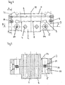
- Fig. 1 of the drawing is a force measuring device in side view shown, which are arranged in parallel one above the other Force 1 and 2 Kraftaus Arthursutz exists, the are each connected laterally to a respective deformation body 3, in each spaced two Meßsenkungspaare 4,5 horizontally are provided.
- the force measuring device is integrally formed and contains above a horizontal bar-shaped force introduction part 1, which is arranged in mounting position transversely under a rail. Therefore, the upper flat bearing surface 6 also corresponds at least the visual foot width. About unillustrated tapped holes is the rail with conventional fasteners firmly screwed onto the force introduction part 1.
- Parallel to the force introduction part 1 is under this a beam-shaped Kraftaus effetsteil 2 arranged horizontally, the can be connected in the longitudinal direction with a threshold.
- the force introduction part 1 and the force extraction part 2 are by a transverse gap 8 of preferably 5mm Height spaced from each other.
- the sides are horizontally stacked arranged Kraftein effets- 1 and Kraltaus effetsmaschine 2 connected by two deformation body 3, in the installed position at least partially arranged vertically are.
- the deformation body 3 are by a round Recess 9 at each end of the horizontal transverse gap 8 approximately semicircular or C-shaped.
- the Meßsenkungspaare 4 are two against each other directed bores 13 formed in detail in Sectional view in Fig. 3 of the drawing are shown.
- there isL between the holes 13 each have a membrane-like connecting wall 12 of preferably 1-5mm thickness provided on the strain gauge 10 in the form of Scherkzaftaufillonn are applied, the bores 13 preferably a Diameter of 35mm.
- these two upper ones Lowering pairs are preferably the horizontal ones Force components detected in a train crossing in the force introduction part 1 are initiated.
- membrane-like connecting walls 16 of the lower Meßsenkungspaare 5 preferably 5 - 15mm thick and provided for detecting the vertical force components, which is essentially proportional to the vertical rail loading is.
- the choice of the wall thickness is determined first Line to the maximum rail load provided and the desired sensitivity.
- the upper one is Lowering pair 4 laterally next to the round recesses 9 provided there is the area under horizontal load with the highest elongation is, so that both the upper 4 as also the lower Meßsenkungspaare 5 in other places of the deformation body 3 could be arranged. It is But it is advantageous that the two upper Meßsenkungspaare 4 in a vertical and the lower Meßsenkungspaare 5 in a horizontal deformation body part 14 are arranged.
- Such a force measuring device is preferably made of a Stainless steel alloy produced and with the help of machining made in one piece.
- the horizontal one Mounting position of such force measuring devices is in Fig. 1 of Drawing shown.
- These are in an unapproachable form Hollow sill 18 two load cells as force measuring device attached to FIG. 1 of the drawing.
- the Hohlschwellcn 18 consist of two U-shaped Ilalbschalen, the side encompass the force measuring devices.
- two special Brackets 19 integrated with which the force measuring device each by two screws 20 through the two transverse holes 7 of Kraftaus effetmaschine 2 are guided attached.
- the force measuring devices preferably have external dimensions of about 425mm length, 240mm width and 195mm height. Thereby These are screwed into the hollow sleepers 18, which in turn only external dimensions of conventional sleepers must have and in relation to these easily replaceable are, without significant changes at the track substructure become necessary.
- the force measuring devices can but also on a conventional threshold by means of special Mounts 19 or together with the entire hollow sleeper be attached, provided this depends on the height of the track body or the track substructure is possible.
Landscapes
- Physics & Mathematics (AREA)
- General Physics & Mathematics (AREA)
- Engineering & Computer Science (AREA)
- Mechanical Engineering (AREA)
- Force Measurement Appropriate To Specific Purposes (AREA)
- Forklifts And Lifting Vehicles (AREA)
- Maintenance And Inspection Apparatuses For Elevators (AREA)
Abstract
Description
Der Erfindung liegt deshalb die Aufgabe zugrunde, eine Vorrichtung zur Messung verschiedener Schienenbelastungen während der Überfahrt schienengebundener Fahrzeuge zu schaffen, die bei einer dynamischen Schienenbelastung insbesondere mindestens die quer und vertikal in die Schiene eingeleiteten Kräfte berücksichtigt.
- Fig. 1:
- die Seitenansicht einer Kraftmessvorrichtung zur Erfassung einer Schienenbelastung;
- Fig. 2:
- ein Schnittbild in Draufsicht auf die Kraftmessvorrichtung in der Schnittcbcne BB;
- Fig. 3:
- ein Schnittbild in Forderansicht der Kraftmessvorrichtung in der Schnittebene AA, und
- Fig. 4:
- zwei in einer Hohlschwelle eingebaute Kraftmessvorrichtungen.
Claims (11)
- Kraftmessvorrichtung zur Erfassung der Schienenbelastung, die quer zwischen mindestens einer Schiene und längs deren Schwelle angeordnet ist, und die aus mindestens einem balkenförmigen Krafteinleitungsteil (1), das mit der Schiene und aus mindestens einem balkenförmigen Kraftausleitungsteil (2), das mit der Schwelle verbindbar ist, besteht, und die parallel und horizontal übereinander angeordnet sind, wobei zwischen den Kraftein- (1) und Kraftausleitungsteilen (2) mindestens ein Messsenkungspaar (4,5) an mindestens einem Verformungskörper (3) vorgesehen ist, dadurch gekennzeichnet, dass das Krafteinleitungsteil (1) durch einen horizontalen Querspalt (8) vom Kraftausleitungsteil (2) beabstandet ist und das beide Teile seitlich mit je einem zumindest teilweise vertikal ausgerichteten Verformungskörper(3) verbunden sind, in denen mindestens vertikal beabstandet je zwei Messsenkungspaare (4,5) vorgesehen sind, wobei das obere Messsenkungspaar (1) zur Erfassung der horizontalen- und das untere Messsenkungspaar zur Erfassung der vertikalen Kräfte vorgesehen ist.
- Kraftmessvorrichtung nach Anspruch 1, dadurch gekennzeichnet, dass der Verformungskörper (3) durch eine runde oder eckige Aussparung (9) am seitlichen Ende des Querspalts (8) etwa halbkreisförmig oder C-förmig ausgebildet ist, wobei seitlich neben der runden oder eckigen Aussparung (9) im vertikalen Teil des Verformungskörpers (3) mindestens ein oberes Messsenkungspaar (4) angeordnet ist.
- Kraftmessvorrichtung nach Anspruch 2, dadurch gekennzeichnet, dass im Verformungskörper (3) unterhalb des oberen Messsenkungspaares (4) mindestens ein unteres Messsenkungspaar (5) in der seitlichen Verlängerung zum Kraftausleitungsteil (2) ungeordnet ist.
- Kraftmessvorrichtung nach einem der vorhergehenden Ansprüche, dadurch gekennzeichnet, dass diene symmetrisch zu einer vertikalen MiLLelfläche (11) ausgebildet ist und somit mindestens zwei Verformungskörper (3) mit zwei oberen- (4) und zwei unteren Messsenkungspaaren (5) enthält.
- Krattmessvorrichtung nach einem der vorhergehenden Ansprüche, dadurch gekennzeichnet, dass der Verformungskörper (3) in der Verlängerung der Kraftein- (1) und Kraftausleitungsteile (2) seitliche schräge Begrenzungsflächen (21) aufweist.
- Kraftmessvorrichtung nach einem der vorhergehenden Ansprüche, dadurch gekennzeichnet, dass die runde Aussparung (9) in Schienenlängsrichtung durchgehend verlauft und als Bohrung oder als Rundung mit unterschiedlichen Steigungs- bzw. Radienwerten ausgebildet ist und Durchmesser von 20 bis 70mm aufweist.
- Kraftmessvorrichtung nach einem der vorhergehenden Ansprüche, dadurch gekennzeichnet, dass die oberen Messsenkungspaare (4) durch zwei entgegengerichtete Bohrungen (13) oder runde oder eckige Aussparungen gebildet sind, die miteinander eine Verbindungswand (12) bilden, an der Dehnungsmessstreifen (10) appliziert sind, wobei dic ßohrungen (13) oder Aussparungen die gleiche Tiefe und Durchmesserwerte von 20 bis 50mm, sowie eine Dicke der Verbindungswand (12) von 1 bis 5mm aufweisen.
- Kraftmessvorrichtung nach einem der vorhergehenden Ansprüche, dadurch gekennzeichnet, dass die unteren Messsenkungspaare (5) durch zwei entgegengerichtete Bohrungen (15) oder runde oder eckige Aussparungen gebildet sind, die miteinander eine Verbindungswand (16) bilden, an der Dehnungsmessstreifen (17) appliziert sind, wobei die Bohrungen (15) oder Aussparungen gleiche Tiete und Durchmesserwerte von 30 bis 80mm sowie eine Wanddicke von 3 bis 15mm aufweisen.
- Kraftmessvorrichtung nach einem der vorhergehenden Ansprüche, dadurch gekennzeichnet, dass der Krafteinleitungsteil (1) eine obere ebene Fläche (6) enthält, die zur Befestigung des Schienenfußes dient und das das Kraitausleitungsteil (2) symmetrisch zu der vertikalen Mittelflache (11) mindestens zwei Querbohrungen (7) zur Verbindung mit einer Schwelle (18) oder einer Halterung (19), die mit einer Schwelle verbindbar ist aufweist.
- Kraftmessvorrichtung nach einem der vorhergehenden Ansprüche, dadurch gekennzeichnet, dass diese in einer Hohlschwelle (18) oder auf einer Schwelle angeordnet ist, wobei mindestens zwei Kraftaufnehmer im Schicnenabstand in der Hohlschwelle (18) oder auf der Schwelle befestigt sind.
- Kraftmessvorrichtung nach Anspruch 10, dadurch gekennzeichnet, dass die Ilohlschwelle (18) aus zwei U-förmigen Metallteilen besteht, die zum Gleisfuß mindestens eine Öffnung aufweist, aus der die obere ebene Fläche (6) des Krafteinleitungsteils (1) herausragt, wobei die Hohlschwelle (18) Außenmaße einer herkömmlichen Schwelle bcsitzt.
Priority Applications (1)
| Application Number | Priority Date | Filing Date | Title |
|---|---|---|---|
| PL05007521T PL1584536T3 (pl) | 2004-04-07 | 2005-04-06 | Urządzenie dynamometryczne do określania obciążenia szyn |
Applications Claiming Priority (2)
| Application Number | Priority Date | Filing Date | Title |
|---|---|---|---|
| DE102004017613 | 2004-04-07 | ||
| DE102004017613A DE102004017613B4 (de) | 2004-04-07 | 2004-04-07 | Kraftmessvorrichtung zur Erfassung der Schienenbelastung |
Publications (3)
| Publication Number | Publication Date |
|---|---|
| EP1584536A2 true EP1584536A2 (de) | 2005-10-12 |
| EP1584536A3 EP1584536A3 (de) | 2007-03-14 |
| EP1584536B1 EP1584536B1 (de) | 2008-06-11 |
Family
ID=34895552
Family Applications (1)
| Application Number | Title | Priority Date | Filing Date |
|---|---|---|---|
| EP05007521A Expired - Lifetime EP1584536B1 (de) | 2004-04-07 | 2005-04-06 | Kraftmessvorrichtung zur Erfassung der Schienenbelastung |
Country Status (4)
| Country | Link |
|---|---|
| EP (1) | EP1584536B1 (de) |
| AT (1) | ATE398060T1 (de) |
| DE (2) | DE102004017613B4 (de) |
| PL (1) | PL1584536T3 (de) |
Families Citing this family (4)
| Publication number | Priority date | Publication date | Assignee | Title |
|---|---|---|---|---|
| DE102006059896B3 (de) | 2006-12-16 | 2008-04-17 | Schenck Process Gmbh | Kraftmessvorrichtung |
| DE102008040195A1 (de) | 2008-07-04 | 2010-01-21 | ME-Meßsysteme GmbH | Vorrichtung und Verfahren zur Erfassung von schienengebundenen Fahrzeugbewegungen |
| DE102010047234B8 (de) * | 2010-10-04 | 2015-12-24 | Schenck Process Gmbh | Wägemodul zur Messung von Radaufstandskräften |
| DE102016001342B3 (de) * | 2016-02-08 | 2017-07-06 | Schenck Process Europe Gmbh | Kraftmessvorrichtung zur Ermittlung der Radaufstandskräfte schienengebundener Fahrzeuge |
Family Cites Families (9)
| Publication number | Priority date | Publication date | Assignee | Title |
|---|---|---|---|---|
| US3159227A (en) * | 1962-09-28 | 1964-12-01 | Sands Measurement Corp | Weighing apparatus |
| FR1390054A (fr) * | 1964-04-21 | 1965-02-19 | Asea Ab | Dispositif pour la pesée de matériel roulant |
| DE2758997C2 (de) * | 1977-12-30 | 1984-10-18 | Reinhold 8011 Kirchseeon Ficht | Meßglied zum Messen des Raddruckes des Rades eines Schienenfahrzeuges |
| DE4023745A1 (de) * | 1990-07-26 | 1992-01-30 | Pfister Gmbh | Schwelle zur auflage von eisenbahnschienen |
| DE59104254D1 (de) * | 1991-02-25 | 1995-02-23 | Schenck Ag Carl | Wägeverfahren. |
| DE4439342C2 (de) * | 1994-11-04 | 1997-02-20 | Deutsche Bahn Ag | Anordnung zur Ermittlung unrunder Räder von Eisenbahnfahrzeugen |
| DE19834030A1 (de) * | 1998-07-28 | 2000-02-03 | Henning Becker | Messschwelle zur Messung des Radgewichts eines Waggons |
| DE19941843A1 (de) * | 1999-09-02 | 2001-03-08 | Schenck Process Gmbh | Vorrichtung zur Feststellung von Unrundheiten und Flachstellen an Rädern bei Schienenfahrzeugen |
| DE10031092A1 (de) * | 2000-06-30 | 2002-01-10 | Schenck Process Gmbh | Wägevorrichtung für Schienenfahrzeuge |
-
2004
- 2004-04-07 DE DE102004017613A patent/DE102004017613B4/de not_active Expired - Fee Related
-
2005
- 2005-04-06 PL PL05007521T patent/PL1584536T3/pl unknown
- 2005-04-06 DE DE502005004368T patent/DE502005004368D1/de not_active Expired - Lifetime
- 2005-04-06 EP EP05007521A patent/EP1584536B1/de not_active Expired - Lifetime
- 2005-04-06 AT AT05007521T patent/ATE398060T1/de active
Also Published As
| Publication number | Publication date |
|---|---|
| DE102004017613B4 (de) | 2006-03-02 |
| ATE398060T1 (de) | 2008-07-15 |
| DE102004017613A1 (de) | 2005-11-03 |
| EP1584536B1 (de) | 2008-06-11 |
| PL1584536T3 (pl) | 2008-10-31 |
| DE502005004368D1 (de) | 2008-07-24 |
| EP1584536A3 (de) | 2007-03-14 |
Similar Documents
| Publication | Publication Date | Title |
|---|---|---|
| DE4439342C2 (de) | Anordnung zur Ermittlung unrunder Räder von Eisenbahnfahrzeugen | |
| AT515578B1 (de) | Vorrichtung zur Hinderniserkennung bei Schienenfahrzeugen | |
| EP1212228B1 (de) | Vorrichtung zur feststellung von unrundheiten und flachstellen an rädern bei schienenfahrzeugen | |
| EP3265774B1 (de) | Diagnoseeinrichtung zur feststellung einer unrundheit an schienenfahrzeugrädern nach einem kraftstoss-auswerteverfahren | |
| DE102010047234B4 (de) | Wägemodul zur Messung von Radaufstandskräften | |
| DE10304008B4 (de) | Vorrichtung zur Messung der Schienenbelastung | |
| EP1904356B1 (de) | Verfahren und vorrichtung zur erfassung der entgleisungsgefahr von schienenfahrzeugen | |
| DE10347812B4 (de) | Kraftmessvorrichtung zur Erfassung der Schienenbelastung | |
| DE69308848T2 (de) | Wägevorrichtung für schienenfahrzeuge | |
| EP1584536B1 (de) | Kraftmessvorrichtung zur Erfassung der Schienenbelastung | |
| DE102007044186A1 (de) | Schiebetritt für Schienenfahrzeuge | |
| DE102005057473B4 (de) | Verfahren und Vorrichtung zur Erfassung von auf eine Schiene einwirkenden Kräften | |
| DE10229512B4 (de) | Verfahren zum Erfassen von Radlasten von Schienenfahrzeugen und mobile Messeinrichtung | |
| DE102019114288A1 (de) | Verfahren und Vorrichtung zur Lokalisierung einer singulären Fehlstelle an der Lauffläche eines Rades eines schienengebundenen Fahrzeugs | |
| DE10031092A1 (de) | Wägevorrichtung für Schienenfahrzeuge | |
| EP1147383B1 (de) | Wägevorrichtung für schienenfahrzeuge | |
| AT516459B1 (de) | Vorrichtung zur Erfassung von Schienenverformungen | |
| DE10114482B4 (de) | Vorrichtung und Verfahren zur dynamischen Messung der Achslast oder des Gewichts von Schienenfahrzeugen | |
| WO2004005864A1 (de) | Messeinrichtung zum erfassen von radlasten | |
| EP1141667B1 (de) | Wägevorrichtung für schienenfahrzeuge | |
| DE2043484C3 (de) | Vorrichtung zum Messen der Belastungen, die durch Fahren von Fahrzeugen auf einer Straße aufgebracht werden | |
| DE20214267U1 (de) | Messeinrichtung zum Erfassen von Radlasten von Schienenfahrzeugen | |
| DE10356867A1 (de) | Messeinrichtung für die Radsatzdiagnose und zum Erfassen von Radaufstandskräften von Schienenfahrzeugen | |
| WO2011110524A1 (de) | Anordnung zum messen der achsdrücke von transportfahrzeugen | |
| DE10009156C1 (de) | Verfahren und Vorrichtung zum Ermitteln der Eigenschaften der Radfederung eines Drehgestells von Schienenfahrzeugen |
Legal Events
| Date | Code | Title | Description |
|---|---|---|---|
| PUAI | Public reference made under article 153(3) epc to a published international application that has entered the european phase |
Free format text: ORIGINAL CODE: 0009012 |
|
| AK | Designated contracting states |
Kind code of ref document: A2 Designated state(s): AT BE BG CH CY CZ DE DK EE ES FI FR GB GR HU IE IS IT LI LT LU MC NL PL PT RO SE SI SK TR |
|
| AX | Request for extension of the european patent |
Extension state: AL BA HR LV MK YU |
|
| RTI1 | Title (correction) |
Free format text: FORCE MEASURING DEVICE FOR THE DETECTION OF THE LOAD ON THE RAILS |
|
| PUAL | Search report despatched |
Free format text: ORIGINAL CODE: 0009013 |
|
| AK | Designated contracting states |
Kind code of ref document: A3 Designated state(s): AT BE BG CH CY CZ DE DK EE ES FI FR GB GR HU IE IS IT LI LT LU MC NL PL PT RO SE SI SK TR |
|
| AX | Request for extension of the european patent |
Extension state: AL BA HR LV MK YU |
|
| 17P | Request for examination filed |
Effective date: 20070522 |
|
| GRAP | Despatch of communication of intention to grant a patent |
Free format text: ORIGINAL CODE: EPIDOSNIGR1 |
|
| AKX | Designation fees paid |
Designated state(s): AT BE BG CH CY CZ DE DK EE ES FI FR GB GR HU IE IS IT LI LT LU MC NL PL PT RO SE SI SK TR |
|
| GRAS | Grant fee paid |
Free format text: ORIGINAL CODE: EPIDOSNIGR3 |
|
| GRAA | (expected) grant |
Free format text: ORIGINAL CODE: 0009210 |
|
| AK | Designated contracting states |
Kind code of ref document: B1 Designated state(s): AT BE BG CH CY CZ DE DK EE ES FI FR GB GR HU IE IS IT LI LT LU MC NL PL PT RO SE SI SK TR |
|
| REG | Reference to a national code |
Ref country code: GB Ref legal event code: FG4D Free format text: NOT ENGLISH |
|
| REG | Reference to a national code |
Ref country code: CH Ref legal event code: NV Representative=s name: TROESCH SCHEIDEGGER WERNER AG Ref country code: CH Ref legal event code: EP |
|
| REF | Corresponds to: |
Ref document number: 502005004368 Country of ref document: DE Date of ref document: 20080724 Kind code of ref document: P |
|
| REG | Reference to a national code |
Ref country code: IE Ref legal event code: FG4D Free format text: LANGUAGE OF EP DOCUMENT: GERMAN |
|
| PG25 | Lapsed in a contracting state [announced via postgrant information from national office to epo] |
Ref country code: SI Free format text: LAPSE BECAUSE OF FAILURE TO SUBMIT A TRANSLATION OF THE DESCRIPTION OR TO PAY THE FEE WITHIN THE PRESCRIBED TIME-LIMIT Effective date: 20080611 |
|
| REG | Reference to a national code |
Ref country code: PL Ref legal event code: T3 |
|
| PG25 | Lapsed in a contracting state [announced via postgrant information from national office to epo] |
Ref country code: NL Free format text: LAPSE BECAUSE OF FAILURE TO SUBMIT A TRANSLATION OF THE DESCRIPTION OR TO PAY THE FEE WITHIN THE PRESCRIBED TIME-LIMIT Effective date: 20080611 |
|
| NLV1 | Nl: lapsed or annulled due to failure to fulfill the requirements of art. 29p and 29m of the patents act | ||
| REG | Reference to a national code |
Ref country code: HU Ref legal event code: AG4A Ref document number: E003750 Country of ref document: HU |
|
| PG25 | Lapsed in a contracting state [announced via postgrant information from national office to epo] |
Ref country code: IS Free format text: LAPSE BECAUSE OF FAILURE TO SUBMIT A TRANSLATION OF THE DESCRIPTION OR TO PAY THE FEE WITHIN THE PRESCRIBED TIME-LIMIT Effective date: 20081011 Ref country code: ES Free format text: LAPSE BECAUSE OF FAILURE TO SUBMIT A TRANSLATION OF THE DESCRIPTION OR TO PAY THE FEE WITHIN THE PRESCRIBED TIME-LIMIT Effective date: 20080922 Ref country code: SE Free format text: LAPSE BECAUSE OF FAILURE TO SUBMIT A TRANSLATION OF THE DESCRIPTION OR TO PAY THE FEE WITHIN THE PRESCRIBED TIME-LIMIT Effective date: 20080911 Ref country code: PT Free format text: LAPSE BECAUSE OF FAILURE TO SUBMIT A TRANSLATION OF THE DESCRIPTION OR TO PAY THE FEE WITHIN THE PRESCRIBED TIME-LIMIT Effective date: 20081111 Ref country code: CZ Free format text: LAPSE BECAUSE OF FAILURE TO SUBMIT A TRANSLATION OF THE DESCRIPTION OR TO PAY THE FEE WITHIN THE PRESCRIBED TIME-LIMIT Effective date: 20080611 Ref country code: LT Free format text: LAPSE BECAUSE OF FAILURE TO SUBMIT A TRANSLATION OF THE DESCRIPTION OR TO PAY THE FEE WITHIN THE PRESCRIBED TIME-LIMIT Effective date: 20080611 |
|
| REG | Reference to a national code |
Ref country code: IE Ref legal event code: FD4D |
|
| PG25 | Lapsed in a contracting state [announced via postgrant information from national office to epo] |
Ref country code: RO Free format text: LAPSE BECAUSE OF FAILURE TO SUBMIT A TRANSLATION OF THE DESCRIPTION OR TO PAY THE FEE WITHIN THE PRESCRIBED TIME-LIMIT Effective date: 20080611 Ref country code: SK Free format text: LAPSE BECAUSE OF FAILURE TO SUBMIT A TRANSLATION OF THE DESCRIPTION OR TO PAY THE FEE WITHIN THE PRESCRIBED TIME-LIMIT Effective date: 20080611 |
|
| PLBE | No opposition filed within time limit |
Free format text: ORIGINAL CODE: 0009261 |
|
| STAA | Information on the status of an ep patent application or granted ep patent |
Free format text: STATUS: NO OPPOSITION FILED WITHIN TIME LIMIT |
|
| PG25 | Lapsed in a contracting state [announced via postgrant information from national office to epo] |
Ref country code: IE Free format text: LAPSE BECAUSE OF FAILURE TO SUBMIT A TRANSLATION OF THE DESCRIPTION OR TO PAY THE FEE WITHIN THE PRESCRIBED TIME-LIMIT Effective date: 20080611 Ref country code: BG Free format text: LAPSE BECAUSE OF FAILURE TO SUBMIT A TRANSLATION OF THE DESCRIPTION OR TO PAY THE FEE WITHIN THE PRESCRIBED TIME-LIMIT Effective date: 20080911 Ref country code: EE Free format text: LAPSE BECAUSE OF FAILURE TO SUBMIT A TRANSLATION OF THE DESCRIPTION OR TO PAY THE FEE WITHIN THE PRESCRIBED TIME-LIMIT Effective date: 20080611 Ref country code: DK Free format text: LAPSE BECAUSE OF FAILURE TO SUBMIT A TRANSLATION OF THE DESCRIPTION OR TO PAY THE FEE WITHIN THE PRESCRIBED TIME-LIMIT Effective date: 20080611 |
|
| 26N | No opposition filed |
Effective date: 20090312 |
|
| PG25 | Lapsed in a contracting state [announced via postgrant information from national office to epo] |
Ref country code: MC Free format text: LAPSE BECAUSE OF NON-PAYMENT OF DUE FEES Effective date: 20090430 |
|
| PGFP | Annual fee paid to national office [announced via postgrant information from national office to epo] |
Ref country code: HU Payment date: 20100506 Year of fee payment: 6 |
|
| PG25 | Lapsed in a contracting state [announced via postgrant information from national office to epo] |
Ref country code: GR Free format text: LAPSE BECAUSE OF FAILURE TO SUBMIT A TRANSLATION OF THE DESCRIPTION OR TO PAY THE FEE WITHIN THE PRESCRIBED TIME-LIMIT Effective date: 20080912 |
|
| PGFP | Annual fee paid to national office [announced via postgrant information from national office to epo] |
Ref country code: BE Payment date: 20100419 Year of fee payment: 6 |
|
| PG25 | Lapsed in a contracting state [announced via postgrant information from national office to epo] |
Ref country code: LU Free format text: LAPSE BECAUSE OF NON-PAYMENT OF DUE FEES Effective date: 20090406 |
|
| PG25 | Lapsed in a contracting state [announced via postgrant information from national office to epo] |
Ref country code: TR Free format text: LAPSE BECAUSE OF FAILURE TO SUBMIT A TRANSLATION OF THE DESCRIPTION OR TO PAY THE FEE WITHIN THE PRESCRIBED TIME-LIMIT Effective date: 20080611 |
|
| PGFP | Annual fee paid to national office [announced via postgrant information from national office to epo] |
Ref country code: FI Payment date: 20110414 Year of fee payment: 7 Ref country code: PL Payment date: 20110406 Year of fee payment: 7 |
|
| PG25 | Lapsed in a contracting state [announced via postgrant information from national office to epo] |
Ref country code: CY Free format text: LAPSE BECAUSE OF FAILURE TO SUBMIT A TRANSLATION OF THE DESCRIPTION OR TO PAY THE FEE WITHIN THE PRESCRIBED TIME-LIMIT Effective date: 20080611 |
|
| BERE | Be: lapsed |
Owner name: HOTTINGER BALDWIN MESSTECHNIK G.M.B.H. Effective date: 20110430 |
|
| PG25 | Lapsed in a contracting state [announced via postgrant information from national office to epo] |
Ref country code: HU Free format text: LAPSE BECAUSE OF NON-PAYMENT OF DUE FEES Effective date: 20110407 Ref country code: BE Free format text: LAPSE BECAUSE OF NON-PAYMENT OF DUE FEES Effective date: 20110430 |
|
| REG | Reference to a national code |
Ref country code: DE Ref legal event code: R082 Ref document number: 502005004368 Country of ref document: DE Representative=s name: SCHWEIZER, JOACHIM, DIPL.-ING., DE |
|
| PG25 | Lapsed in a contracting state [announced via postgrant information from national office to epo] |
Ref country code: FI Free format text: LAPSE BECAUSE OF NON-PAYMENT OF DUE FEES Effective date: 20120406 |
|
| REG | Reference to a national code |
Ref country code: PL Ref legal event code: LAPE |
|
| PG25 | Lapsed in a contracting state [announced via postgrant information from national office to epo] |
Ref country code: PL Free format text: LAPSE BECAUSE OF NON-PAYMENT OF DUE FEES Effective date: 20120406 |
|
| REG | Reference to a national code |
Ref country code: FR Ref legal event code: PLFP Year of fee payment: 12 |
|
| REG | Reference to a national code |
Ref country code: FR Ref legal event code: PLFP Year of fee payment: 13 |
|
| REG | Reference to a national code |
Ref country code: FR Ref legal event code: PLFP Year of fee payment: 14 |
|
| PGFP | Annual fee paid to national office [announced via postgrant information from national office to epo] |
Ref country code: FR Payment date: 20200824 Year of fee payment: 16 Ref country code: GB Payment date: 20200828 Year of fee payment: 16 Ref country code: DE Payment date: 20200824 Year of fee payment: 16 |
|
| PGFP | Annual fee paid to national office [announced via postgrant information from national office to epo] |
Ref country code: AT Payment date: 20200826 Year of fee payment: 16 Ref country code: CH Payment date: 20200828 Year of fee payment: 16 Ref country code: IT Payment date: 20200826 Year of fee payment: 16 |
|
| REG | Reference to a national code |
Ref country code: DE Ref legal event code: R082 Ref document number: 502005004368 Country of ref document: DE Representative=s name: SCHWEIZER, JOACHIM, DIPL.-ING., DE Ref country code: DE Ref legal event code: R081 Ref document number: 502005004368 Country of ref document: DE Owner name: HOTTINGER BRUEEL & KJAER GMBH, DE Free format text: FORMER OWNER: HOTTINGER BALDWIN MESSTECHNIK GMBH, 64293 DARMSTADT, DE |
|
| REG | Reference to a national code |
Ref country code: DE Ref legal event code: R119 Ref document number: 502005004368 Country of ref document: DE |
|
| REG | Reference to a national code |
Ref country code: AT Ref legal event code: MM01 Ref document number: 398060 Country of ref document: AT Kind code of ref document: T Effective date: 20210406 |
|
| GBPC | Gb: european patent ceased through non-payment of renewal fee |
Effective date: 20210406 |
|
| PG25 | Lapsed in a contracting state [announced via postgrant information from national office to epo] |
Ref country code: DE Free format text: LAPSE BECAUSE OF NON-PAYMENT OF DUE FEES Effective date: 20211103 Ref country code: FR Free format text: LAPSE BECAUSE OF NON-PAYMENT OF DUE FEES Effective date: 20210430 Ref country code: GB Free format text: LAPSE BECAUSE OF NON-PAYMENT OF DUE FEES Effective date: 20210406 Ref country code: LI Free format text: LAPSE BECAUSE OF NON-PAYMENT OF DUE FEES Effective date: 20210430 Ref country code: AT Free format text: LAPSE BECAUSE OF NON-PAYMENT OF DUE FEES Effective date: 20210406 Ref country code: CH Free format text: LAPSE BECAUSE OF NON-PAYMENT OF DUE FEES Effective date: 20210430 |
|
| PG25 | Lapsed in a contracting state [announced via postgrant information from national office to epo] |
Ref country code: IT Free format text: LAPSE BECAUSE OF NON-PAYMENT OF DUE FEES Effective date: 20200406 |
|
| PG25 | Lapsed in a contracting state [announced via postgrant information from national office to epo] |
Ref country code: IT Free format text: LAPSE BECAUSE OF NON-PAYMENT OF DUE FEES Effective date: 20210406 |