EP1584539A2 - Système de direction hydro-statique - Google Patents
Système de direction hydro-statique Download PDFInfo
- Publication number
- EP1584539A2 EP1584539A2 EP05005566A EP05005566A EP1584539A2 EP 1584539 A2 EP1584539 A2 EP 1584539A2 EP 05005566 A EP05005566 A EP 05005566A EP 05005566 A EP05005566 A EP 05005566A EP 1584539 A2 EP1584539 A2 EP 1584539A2
- Authority
- EP
- European Patent Office
- Prior art keywords
- steering
- steering angle
- setting device
- angle setting
- drive
- Prior art date
- Legal status (The legal status is an assumption and is not a legal conclusion. Google has not performed a legal analysis and makes no representation as to the accuracy of the status listed.)
- Granted
Links
- 230000002706 hydrostatic effect Effects 0.000 title claims abstract description 9
- 230000004044 response Effects 0.000 claims abstract description 8
- 239000007788 liquid Substances 0.000 claims abstract description 3
- 238000012937 correction Methods 0.000 description 5
- 230000001360 synchronised effect Effects 0.000 description 2
- 230000006978 adaptation Effects 0.000 description 1
- 230000000694 effects Effects 0.000 description 1
- 239000012530 fluid Substances 0.000 description 1
- 230000006870 function Effects 0.000 description 1
Images
Classifications
-
- B—PERFORMING OPERATIONS; TRANSPORTING
- B62—LAND VEHICLES FOR TRAVELLING OTHERWISE THAN ON RAILS
- B62D—MOTOR VEHICLES; TRAILERS
- B62D5/00—Power-assisted or power-driven steering
- B62D5/06—Power-assisted or power-driven steering fluid, i.e. using a pressurised fluid for most or all the force required for steering a vehicle
- B62D5/09—Power-assisted or power-driven steering fluid, i.e. using a pressurised fluid for most or all the force required for steering a vehicle characterised by means for actuating valves
- B62D5/091—Hydraulic steer-by-wire systems, e.g. the valve being actuated by an electric motor
-
- B—PERFORMING OPERATIONS; TRANSPORTING
- B62—LAND VEHICLES FOR TRAVELLING OTHERWISE THAN ON RAILS
- B62D—MOTOR VEHICLES; TRAILERS
- B62D5/00—Power-assisted or power-driven steering
- B62D5/008—Changing the transfer ratio between the steering wheel and the steering gear by variable supply of energy, e.g. by using a superposition gear
-
- B—PERFORMING OPERATIONS; TRANSPORTING
- B62—LAND VEHICLES FOR TRAVELLING OTHERWISE THAN ON RAILS
- B62D—MOTOR VEHICLES; TRAILERS
- B62D6/00—Arrangements for automatically controlling steering depending on driving conditions sensed and responded to, e.g. control circuits
Definitions
- the invention relates to a hydrostatic steering system for vehicles, including a steering angle setting device (e.g. a steering wheel) acting on a steering valve.
- the steering valve controls a steering drive by connecting a source of liquid under pressure with a steering cylinder in response to movement of the steering angle setting device.
- the steering system includes a sensor coordinated with the steering angle setting device to detect the set value of a steering angle.
- a sensor coordinated with the steering drive is provided to detect the actual value of steering angle achieved.
- a correcting control device compares the set value and the actual value of a steering angle and synchronizes the position of the steering angle setting device (steering wheel) and the position of the steering drive to correct any difference.
- Steering gears of this kind are known from DE 10300686 A1.
- this prior art is directed to a hydraulic correction means which reaches a synchronization of the steering angle only when the vehicle is driving in a straight ahead condition.
- This correction means cannot be used when driving at higher speeds or when driving through a curve. When driving curves, the steering performance will not give satisfaction.
- a hydrostatic steering system for vehicles having the features of the preamble of claim 1 which includes a corrective gear means connected between the steering angle setting device and the steering valve, the corrective gear means having a first input member connected with the steering angle setting device and with the output member of the corrective gear means, and a second input member also connected with the output member, the movement of the second input member being adjustable by the control device in response to different vehicle operation modes to synchronise the set and actual values of steering angle.
- the hydrostatic steering of the present invention is especially useful for commercial vehicles, such as tractors, which are driven in different operational modes and using higher speeds. Often, the operation if the steering motion is directed to the kind of use of the vehicle.
- the control device is equipped with a microcomputer which gives the possibility to steer the vehicle in the known manner in the "normal driving" operation mode using a steering wheel as the steering angle setting device.
- the control device gives signals for correction at all the times to the corrective gear. Consequently, the position of the steering angle setting device is synchronised with the position of a steering drive.
- a further "reverse drive” operational mode is useful for vehicles which are used in both driving directions.
- the seat for the driver together with the steering wheel is preferably turned as a unit in the vehicle cab into the desired direction of drive.
- This turning motion is not possible on all commercial vehicles having limited cab room. Consequently, it is only the seat of the driver which is turned without turning the steering wheel.
- the steering system of the present invention enables, for example, a joystick positioned in the rear of the cab to act as a reverse driving steering angle setting device which is in connection with the control device.
- the reverse driving facility can be provided relatively easily with system of the present invention.
- the steering system of the present invention can also easily provide a further operational mode in which the vehicle is driven automatically along a given "lane line" defined by a GPS system.
- a GPS sensor is provided which receives position signals which are passed to the control device.
- the control device generates a series of steering angle signals to steer the vehicle parallel to a previously manually driven lane, the control device comparing these generated steering angle signals with the signals from the second sensor and adjusting the position of the second input member to synchronise these signals.
- the result is a better guiding of the vehicle along the lane line compared with known steering systems.
- the corrective gear may be a planetary gear having a first input member in form of a first sun wheel and a second sun wheel which acts as an output member, both sun wheels meshing with respective planet gears which are connected by shafts, the shafts being supported in a planet carrier which acts as the second input member and which is rotatable by an electric motor.
- the planetary carrier may be equipped on its outside with outer toothing which meshes with a worm wheel which is driven by the electric motor which is in turn controlled by signals from the control device.
- the steering angle setting device When operating, in "reverse drive” mode the steering angle setting device is arranged to be locked so that the input into the corrective gear is via the second input member.
- the steering angle setting device is locked by a brake which means that the driver does not need to hold the steering wheel fixed by hand but he can override the automatic "lane line guiding" steering to make corrective actions if needed.
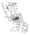
- the steering system comprises a steering angle setting device 1 having two shafts 1a, 1b and a steering wheel 2 fixed to the end of shaft 1a.
- the other end of the steering angle setting device 1 is in driving connection with a steering valve 3.
- the steering valve 3 is connected by two conduits 7, 8 with the source 6 of fluid under pressure and by two further conduits 4 and 5 with a steering cylinder 9 of the steering system.
- the steering cylinder 9 is connected to the wheels of the vehicle by a rod assembly 10.
- a corrective gear 11 is arranged between the two shafts 1a and 1b.
- the gear 11 is a planetary gear having an inner multiplication.
- the end of the shaft 1a is in fixed drive connection with a sun wheel 12 which is part of the gear 11.
- the end of shaft 1b, facing shaft 1a, is in fixed drive connection with a further sun wheel 13 of the gear 11.
- Sun wheels 12 and 13 have different diameters. It is not important which sun wheel of the sun wheels 12 and 13 has the larger diameter. In the shown example it is the sun wheel 12 which has a diameter about 20% larger than the diameter of the sun wheel 12.
- the sun wheel 12 which is fixed on shaft 1a is a first input member of the gear 11.
- the sun wheel 12 meshes with three planetary wheels 14 forming a set.
- Sun wheel 13 also meshes with three planetary wheels 15.
- Each planetary wheel 14 is connected with a planetary wheel 15 by a common shaft 16.
- Shafts 16 are supported in a planet carrier 17 which is the housing of the gear 11. Consequently, the two sets of planetary wheels rotate with each other.
- An outer toothing 17a is provided on the outer circumference of planet carrier 17.
- a worm wheel 19, which is driven by an electric motor 18 meshes with this outer toothing 17a.
- the worm wheel 19 is designed and arranged to be self-blocking.
- the direction of rotation and the number of revolutions of the electric motor 18 is controlled by a control device 20 including a microprocessor.
- the electric motor 18 drives the worm wheel 19 resulting in a rotational motion of the planet carrier 17. This motion is substantially reduced due to the inner multiplication of the gear for super positioning 11.
- the motion is transferred from the planetary wheels 14, 15 to the sun wheel 13. Consequently, shaft 1b is driven with an additional motion of rotation.
- the planet carrier 17 is the second input member.
- Sun wheel 13 is the output member of the corrective gear 11.
- the control device 20 is connected with a sensor 21 which acts on shaft 1a to detect the value of the steering angle set by the steering wheel 2.
- a sensor 22 is arranged on the steering drive 9 to detect the actual value of the steering motion. Both signals are used within the control device 20 during a first "normal drive" operational mode.
- Control device 20 continuously makes a comparison between the set valve from sensor 21 and the actual value if the steering motion from sensor 22. In this way the position of the steering angle transmitter 1 is synchronised with the position of the rod assembly 10 by actuation of electric motor 18.
- the control device includes a digital memory in which the set values of the position of the steering angle setting device 1 and the actual values of the position of the steering drive are compared with each other.
- the control device 20 has two further inputs.
- a second steering angle setting device 23 in the form of a joystick is provided to be used for the "reverse driving" operational mode.
- a further sensor 24 is provided to be used in a further “lane line guiding” operational mode.
- the driver When operating in the "reverse driving" mode, which may be initiated manually or automatically in response to the position of the driver's seat, the driver does not actuate the steering angle setting device 1 but only a steering angle setting device in the form of a joystick 23 which is located in the rear of the vehicle cab. Consequently, within the control device 20 signals are generated by comparison of set values from joystick 23 and actual values from sensor 22.
- a proper steering of the vehicle in this operational mode is only possible with the steering angle setting device 1 held fixed for the time this mode is operated. Consequently, any unwanted influence by the steering angle transmitter 1 is avoided.
- a braking device 25 may be arranged on the shaft 1a. The braking device 25 is actuated during this operational mode by the control device 20. Thus, the steering angle transmitter 1 is fixed and cannot be moved.
- the control device includes a further digital memory in which the comparison of the set values from the joystick 23 are compared with the actual values of the position of the steering drive from sensor 22.
- a GPS sensor 24 detects the starting and finishing points of this initial straight lane and, with the operator having entered into the GPS system the working width of the vehicle, the system can generate the path to be followed for subsequent straight lanes which are parallel to the first manually steered lane.
- the GPS signals received via sensor 24 are fed into control device 20 where the steering angle values required for the guided lanes are generated by additional digital processing memory. These generated values are compared with the actual steering angle valves from sensor 22 as before and electric motor 18 is controlled to make the necessary corrections via planet carrier 17.
- the braking device 25 is again activated in this mode to make sure any influence by the steering angle setting device 1 is avoided and to guarantee the proper function of the gear 11. In this operational mode the braking moment of braking device 25 is limited to give the driver the possibility to move the steering wheel 2 if required with a high force to interfere with or adjust the steering motion.
- the "lane line guiding" mode is initiated by operating an appropriate manual switch. For safety this mode should only be used at speeds lower than 20km/n as is usual when working in the field.
Landscapes
- Engineering & Computer Science (AREA)
- Chemical & Material Sciences (AREA)
- Combustion & Propulsion (AREA)
- Transportation (AREA)
- Mechanical Engineering (AREA)
- Steering Control In Accordance With Driving Conditions (AREA)
Applications Claiming Priority (2)
| Application Number | Priority Date | Filing Date | Title |
|---|---|---|---|
| GB0407998 | 2004-04-07 | ||
| GB0407998A GB0407998D0 (en) | 2004-04-07 | 2004-04-07 | Hydrostatic steering systems |
Publications (3)
| Publication Number | Publication Date |
|---|---|
| EP1584539A2 true EP1584539A2 (fr) | 2005-10-12 |
| EP1584539A3 EP1584539A3 (fr) | 2005-11-16 |
| EP1584539B1 EP1584539B1 (fr) | 2008-01-02 |
Family
ID=32320575
Family Applications (1)
| Application Number | Title | Priority Date | Filing Date |
|---|---|---|---|
| EP05005566A Expired - Lifetime EP1584539B1 (fr) | 2004-04-07 | 2005-03-15 | Système de direction hydro-statique |
Country Status (3)
| Country | Link |
|---|---|
| EP (1) | EP1584539B1 (fr) |
| DE (1) | DE602005004057T2 (fr) |
| GB (1) | GB0407998D0 (fr) |
Cited By (6)
| Publication number | Priority date | Publication date | Assignee | Title |
|---|---|---|---|---|
| EP2757867B1 (fr) | 2011-09-07 | 2018-07-11 | CNH Industrial Italia S.p.A. | Véhicule pouvant être dirigé |
| WO2019092516A1 (fr) * | 2017-11-10 | 2019-05-16 | Same Deutz-Fahr Italia S.P.A. | Ensemble de réglage d'un système de direction hydraulique d'un véhicule |
| CN112623025A (zh) * | 2021-01-18 | 2021-04-09 | 临工集团济南重机有限公司 | 一种自动转向控制系统、控制方法及矿用自卸车 |
| WO2022152249A1 (fr) * | 2021-01-18 | 2022-07-21 | 北京九曜智能科技有限公司 | Système de commande de direction et procédé de commande de direction |
| WO2024051786A1 (fr) * | 2022-09-08 | 2024-03-14 | 北京九曜智能科技有限公司 | Système de commande de transformation de direction assistée hydraulique à conduite autonome et procédé de commande |
| JP2024056094A (ja) * | 2018-01-23 | 2024-04-19 | 株式会社クボタ | 作業車両 |
Families Citing this family (1)
| Publication number | Priority date | Publication date | Assignee | Title |
|---|---|---|---|---|
| DE102010001744A1 (de) * | 2010-02-10 | 2011-08-11 | ZF Lenksysteme GmbH, 73527 | Verfahren zur Optimierung eines hydrostatischen Lenksystems in einem Fahrzeug |
Citations (1)
| Publication number | Priority date | Publication date | Assignee | Title |
|---|---|---|---|---|
| DE10300686A1 (de) | 2002-04-18 | 2003-10-30 | Still Gmbh | Hydraulische Lenkeinrichtung |
Family Cites Families (4)
| Publication number | Priority date | Publication date | Assignee | Title |
|---|---|---|---|---|
| DE1947205A1 (de) * | 1969-09-18 | 1971-04-08 | Zahnradfabrik Friedrichshafen | Hydrostatische Lenkanlage,insbesondere fuer Kraftfahrzeuge |
| DE10210368A1 (de) * | 2002-03-08 | 2003-09-25 | Daimler Chrysler Ag | Lenkwellenstrang |
| DE20304336U1 (de) * | 2003-03-18 | 2003-07-31 | TRW Fahrwerksysteme GmbH & Co KG, 40547 Düsseldorf | Servolenksystem |
| DE502004003374D1 (de) * | 2003-08-16 | 2007-05-16 | Bayerische Motoren Werke Ag | Lenksystem für ein Kraftfahrzeug mit einer Servolenkeinrichtung |
-
2004
- 2004-04-07 GB GB0407998A patent/GB0407998D0/en not_active Ceased
-
2005
- 2005-03-15 DE DE200560004057 patent/DE602005004057T2/de not_active Expired - Lifetime
- 2005-03-15 EP EP05005566A patent/EP1584539B1/fr not_active Expired - Lifetime
Patent Citations (1)
| Publication number | Priority date | Publication date | Assignee | Title |
|---|---|---|---|---|
| DE10300686A1 (de) | 2002-04-18 | 2003-10-30 | Still Gmbh | Hydraulische Lenkeinrichtung |
Cited By (11)
| Publication number | Priority date | Publication date | Assignee | Title |
|---|---|---|---|---|
| EP2757867B1 (fr) | 2011-09-07 | 2018-07-11 | CNH Industrial Italia S.p.A. | Véhicule pouvant être dirigé |
| WO2019092516A1 (fr) * | 2017-11-10 | 2019-05-16 | Same Deutz-Fahr Italia S.P.A. | Ensemble de réglage d'un système de direction hydraulique d'un véhicule |
| CN111315636A (zh) * | 2017-11-10 | 2020-06-19 | 赛迈道依茨-法尔意大利股份公司 | 车辆的液压转向系统的调节组件 |
| CN111315636B (zh) * | 2017-11-10 | 2022-02-25 | 赛迈道依茨-法尔意大利股份公司 | 车辆的液压转向系统的调节组件 |
| US11459014B2 (en) | 2017-11-10 | 2022-10-04 | Same Deutz-Fahr Italia S.P.A. | Adjustment assembly of a hydraulic steering system of a vehicle |
| JP2024056094A (ja) * | 2018-01-23 | 2024-04-19 | 株式会社クボタ | 作業車両 |
| JP7575629B2 (ja) | 2018-01-23 | 2024-10-29 | 株式会社クボタ | 作業車両 |
| CN112623025A (zh) * | 2021-01-18 | 2021-04-09 | 临工集团济南重机有限公司 | 一种自动转向控制系统、控制方法及矿用自卸车 |
| WO2022152249A1 (fr) * | 2021-01-18 | 2022-07-21 | 北京九曜智能科技有限公司 | Système de commande de direction et procédé de commande de direction |
| WO2024051786A1 (fr) * | 2022-09-08 | 2024-03-14 | 北京九曜智能科技有限公司 | Système de commande de transformation de direction assistée hydraulique à conduite autonome et procédé de commande |
| EP4393792A4 (fr) * | 2022-09-08 | 2025-03-19 | Beijing Navagraha Intelligent Technology Co., Ltd. | Système de commande de transformation de direction assistée hydraulique à conduite autonome et procédé de commande |
Also Published As
| Publication number | Publication date |
|---|---|
| DE602005004057D1 (de) | 2008-02-14 |
| EP1584539A3 (fr) | 2005-11-16 |
| GB0407998D0 (en) | 2004-05-12 |
| DE602005004057T2 (de) | 2008-12-24 |
| EP1584539B1 (fr) | 2008-01-02 |
Similar Documents
| Publication | Publication Date | Title |
|---|---|---|
| US10131375B2 (en) | Vehicle steering system | |
| EP0822130B1 (fr) | Dispositif de correction de l'angle de direction d'un véhicule | |
| JP2819383B2 (ja) | 制御装置特に自動車の舵取り装置 | |
| US5285867A (en) | Steering arrangement | |
| EP3934963B1 (fr) | Appareil destiné à être utilisé pour tourner des roues de véhicule orientables | |
| DE102007013267B4 (de) | Fahrzeuglenkungssystem | |
| JP2008184004A (ja) | 車両用操舵装置 | |
| GB2306928A (en) | Power steering for motor vehicles | |
| CN101959741A (zh) | 转向操纵装置 | |
| US20050016791A1 (en) | Steering control system | |
| EP1584539B1 (fr) | Système de direction hydro-statique | |
| US20070235240A1 (en) | Power Steering | |
| EP3492344B1 (fr) | Véhicule ayant un rapport de direction variable | |
| JPH07196049A (ja) | 車両用操舵装置 | |
| US6138787A (en) | Motor-driven system for steering a vehicle | |
| JP3934082B2 (ja) | 走行支援装置 | |
| JPS6192964A (ja) | 車両用操舵装置 | |
| JP2951376B2 (ja) | 電動パワーステアリング装置 | |
| JP2001122145A (ja) | 車両用自動操舵装置 | |
| US20180237061A1 (en) | Power steering assembly comprising steering torque overlay | |
| US11459014B2 (en) | Adjustment assembly of a hydraulic steering system of a vehicle | |
| JPH1081152A (ja) | クローラ式走行装置の差動装置 | |
| JPH0699826A (ja) | 操舵装置 | |
| KR20060101977A (ko) | 차량용 능동 전륜 조향 시스템 | |
| CN108100023B (zh) | 一种转向管柱及转向管柱总成 |
Legal Events
| Date | Code | Title | Description |
|---|---|---|---|
| PUAI | Public reference made under article 153(3) epc to a published international application that has entered the european phase |
Free format text: ORIGINAL CODE: 0009012 |
|
| PUAL | Search report despatched |
Free format text: ORIGINAL CODE: 0009013 |
|
| AK | Designated contracting states |
Kind code of ref document: A2 Designated state(s): AT BE BG CH CY CZ DE DK EE ES FI FR GB GR HU IE IS IT LI LT LU MC NL PL PT RO SE SI SK TR |
|
| AX | Request for extension of the european patent |
Extension state: AL BA HR LV MK YU |
|
| AK | Designated contracting states |
Kind code of ref document: A3 Designated state(s): AT BE BG CH CY CZ DE DK EE ES FI FR GB GR HU IE IS IT LI LT LU MC NL PL PT RO SE SI SK TR |
|
| AX | Request for extension of the european patent |
Extension state: AL BA HR LV MK YU |
|
| 17P | Request for examination filed |
Effective date: 20060516 |
|
| AKX | Designation fees paid |
Designated state(s): DE FR GB IT |
|
| 17Q | First examination report despatched |
Effective date: 20060725 |
|
| GRAP | Despatch of communication of intention to grant a patent |
Free format text: ORIGINAL CODE: EPIDOSNIGR1 |
|
| GRAC | Information related to communication of intention to grant a patent modified |
Free format text: ORIGINAL CODE: EPIDOSCIGR1 |
|
| RIC1 | Information provided on ipc code assigned before grant |
Ipc: B62D 6/00 20060101ALI20070612BHEP Ipc: B62D 5/00 20060101AFI20070612BHEP Ipc: B62D 5/09 20060101ALI20070612BHEP Ipc: B62D 1/28 20060101ALI20070612BHEP |
|
| GRAS | Grant fee paid |
Free format text: ORIGINAL CODE: EPIDOSNIGR3 |
|
| GRAA | (expected) grant |
Free format text: ORIGINAL CODE: 0009210 |
|
| AK | Designated contracting states |
Kind code of ref document: B1 Designated state(s): DE FR GB IT |
|
| REG | Reference to a national code |
Ref country code: GB Ref legal event code: FG4D |
|
| REF | Corresponds to: |
Ref document number: 602005004057 Country of ref document: DE Date of ref document: 20080214 Kind code of ref document: P |
|
| ET | Fr: translation filed | ||
| PLBE | No opposition filed within time limit |
Free format text: ORIGINAL CODE: 0009261 |
|
| STAA | Information on the status of an ep patent application or granted ep patent |
Free format text: STATUS: NO OPPOSITION FILED WITHIN TIME LIMIT |
|
| 26N | No opposition filed |
Effective date: 20081003 |
|
| REG | Reference to a national code |
Ref country code: FR Ref legal event code: PLFP Year of fee payment: 11 |
|
| PGFP | Annual fee paid to national office [announced via postgrant information from national office to epo] |
Ref country code: DE Payment date: 20150320 Year of fee payment: 11 |
|
| PGFP | Annual fee paid to national office [announced via postgrant information from national office to epo] |
Ref country code: GB Payment date: 20150319 Year of fee payment: 11 Ref country code: FR Payment date: 20150319 Year of fee payment: 11 |
|
| PGFP | Annual fee paid to national office [announced via postgrant information from national office to epo] |
Ref country code: IT Payment date: 20150330 Year of fee payment: 11 |
|
| REG | Reference to a national code |
Ref country code: DE Ref legal event code: R119 Ref document number: 602005004057 Country of ref document: DE |
|
| GBPC | Gb: european patent ceased through non-payment of renewal fee |
Effective date: 20160315 |
|
| REG | Reference to a national code |
Ref country code: FR Ref legal event code: ST Effective date: 20161130 |
|
| PG25 | Lapsed in a contracting state [announced via postgrant information from national office to epo] |
Ref country code: GB Free format text: LAPSE BECAUSE OF NON-PAYMENT OF DUE FEES Effective date: 20160315 Ref country code: FR Free format text: LAPSE BECAUSE OF NON-PAYMENT OF DUE FEES Effective date: 20160331 Ref country code: DE Free format text: LAPSE BECAUSE OF NON-PAYMENT OF DUE FEES Effective date: 20161001 |
|
| PG25 | Lapsed in a contracting state [announced via postgrant information from national office to epo] |
Ref country code: IT Free format text: LAPSE BECAUSE OF NON-PAYMENT OF DUE FEES Effective date: 20160315 |