EP1584606A1 - Verfahren zur biologischen Wassergewinnung aus Abwasser mit Hilfe eines Wirbelbettreaktors - Google Patents
Verfahren zur biologischen Wassergewinnung aus Abwasser mit Hilfe eines Wirbelbettreaktors Download PDFInfo
- Publication number
- EP1584606A1 EP1584606A1 EP05005114A EP05005114A EP1584606A1 EP 1584606 A1 EP1584606 A1 EP 1584606A1 EP 05005114 A EP05005114 A EP 05005114A EP 05005114 A EP05005114 A EP 05005114A EP 1584606 A1 EP1584606 A1 EP 1584606A1
- Authority
- EP
- European Patent Office
- Prior art keywords
- wastewater
- bed reactor
- water
- treatment
- fluidized bed
- Prior art date
- Legal status (The legal status is an assumption and is not a legal conclusion. Google has not performed a legal analysis and makes no representation as to the accuracy of the status listed.)
- Granted
Links
Images

Classifications
-
- B—PERFORMING OPERATIONS; TRANSPORTING
- B01—PHYSICAL OR CHEMICAL PROCESSES OR APPARATUS IN GENERAL
- B01D—SEPARATION
- B01D21/00—Separation of suspended solid particles from liquids by sedimentation
- B01D21/24—Feed or discharge mechanisms for settling tanks
- B01D21/2488—Feed or discharge mechanisms for settling tanks bringing about a partial recirculation of the liquid, e.g. for introducing chemical aids
-
- B—PERFORMING OPERATIONS; TRANSPORTING
- B01—PHYSICAL OR CHEMICAL PROCESSES OR APPARATUS IN GENERAL
- B01D—SEPARATION
- B01D21/00—Separation of suspended solid particles from liquids by sedimentation
-
- B—PERFORMING OPERATIONS; TRANSPORTING
- B01—PHYSICAL OR CHEMICAL PROCESSES OR APPARATUS IN GENERAL
- B01D—SEPARATION
- B01D21/00—Separation of suspended solid particles from liquids by sedimentation
- B01D21/0012—Settling tanks making use of filters, e.g. by floating layers of particulate material
-
- B—PERFORMING OPERATIONS; TRANSPORTING
- B01—PHYSICAL OR CHEMICAL PROCESSES OR APPARATUS IN GENERAL
- B01D—SEPARATION
- B01D21/00—Separation of suspended solid particles from liquids by sedimentation
- B01D21/0039—Settling tanks provided with contact surfaces, e.g. baffles, particles
-
- B—PERFORMING OPERATIONS; TRANSPORTING
- B01—PHYSICAL OR CHEMICAL PROCESSES OR APPARATUS IN GENERAL
- B01D—SEPARATION
- B01D21/00—Separation of suspended solid particles from liquids by sedimentation
- B01D21/0039—Settling tanks provided with contact surfaces, e.g. baffles, particles
- B01D21/0045—Plurality of essentially parallel plates
-
- B—PERFORMING OPERATIONS; TRANSPORTING
- B01—PHYSICAL OR CHEMICAL PROCESSES OR APPARATUS IN GENERAL
- B01D—SEPARATION
- B01D21/00—Separation of suspended solid particles from liquids by sedimentation
- B01D21/0039—Settling tanks provided with contact surfaces, e.g. baffles, particles
- B01D21/0057—Settling tanks provided with contact surfaces, e.g. baffles, particles with counter-current flow direction of liquid and solid particles
-
- B—PERFORMING OPERATIONS; TRANSPORTING
- B01—PHYSICAL OR CHEMICAL PROCESSES OR APPARATUS IN GENERAL
- B01D—SEPARATION
- B01D21/00—Separation of suspended solid particles from liquids by sedimentation
- B01D21/02—Settling tanks with single outlets for the separated liquid
- B01D21/08—Settling tanks with single outlets for the separated liquid provided with flocculating compartments
-
- C—CHEMISTRY; METALLURGY
- C02—TREATMENT OF WATER, WASTE WATER, SEWAGE, OR SLUDGE
- C02F—TREATMENT OF WATER, WASTE WATER, SEWAGE, OR SLUDGE
- C02F3/00—Biological treatment of water, waste water, or sewage
- C02F3/02—Aerobic processes
- C02F3/08—Aerobic processes using moving contact bodies
- C02F3/085—Fluidized beds
- C02F3/087—Floating beds with contact bodies having a lower density than water
-
- C—CHEMISTRY; METALLURGY
- C02—TREATMENT OF WATER, WASTE WATER, SEWAGE, OR SLUDGE
- C02F—TREATMENT OF WATER, WASTE WATER, SEWAGE, OR SLUDGE
- C02F9/00—Multistage treatment of water, waste water or sewage
-
- C—CHEMISTRY; METALLURGY
- C02—TREATMENT OF WATER, WASTE WATER, SEWAGE, OR SLUDGE
- C02F—TREATMENT OF WATER, WASTE WATER, SEWAGE, OR SLUDGE
- C02F1/00—Treatment of water, waste water, or sewage
- C02F1/001—Processes for the treatment of water whereby the filtration technique is of importance
-
- C—CHEMISTRY; METALLURGY
- C02—TREATMENT OF WATER, WASTE WATER, SEWAGE, OR SLUDGE
- C02F—TREATMENT OF WATER, WASTE WATER, SEWAGE, OR SLUDGE
- C02F1/00—Treatment of water, waste water, or sewage
- C02F1/30—Treatment of water, waste water, or sewage by irradiation
- C02F1/32—Treatment of water, waste water, or sewage by irradiation with ultraviolet light
-
- C—CHEMISTRY; METALLURGY
- C02—TREATMENT OF WATER, WASTE WATER, SEWAGE, OR SLUDGE
- C02F—TREATMENT OF WATER, WASTE WATER, SEWAGE, OR SLUDGE
- C02F1/00—Treatment of water, waste water, or sewage
- C02F1/44—Treatment of water, waste water, or sewage by dialysis, osmosis or reverse osmosis
-
- C—CHEMISTRY; METALLURGY
- C02—TREATMENT OF WATER, WASTE WATER, SEWAGE, OR SLUDGE
- C02F—TREATMENT OF WATER, WASTE WATER, SEWAGE, OR SLUDGE
- C02F1/00—Treatment of water, waste water, or sewage
- C02F1/44—Treatment of water, waste water, or sewage by dialysis, osmosis or reverse osmosis
- C02F1/444—Treatment of water, waste water, or sewage by dialysis, osmosis or reverse osmosis by ultrafiltration or microfiltration
-
- C—CHEMISTRY; METALLURGY
- C02—TREATMENT OF WATER, WASTE WATER, SEWAGE, OR SLUDGE
- C02F—TREATMENT OF WATER, WASTE WATER, SEWAGE, OR SLUDGE
- C02F1/00—Treatment of water, waste water, or sewage
- C02F1/52—Treatment of water, waste water, or sewage by flocculation or precipitation of suspended impurities
- C02F1/54—Treatment of water, waste water, or sewage by flocculation or precipitation of suspended impurities using organic material
- C02F1/56—Macromolecular compounds
-
- C—CHEMISTRY; METALLURGY
- C02—TREATMENT OF WATER, WASTE WATER, SEWAGE, OR SLUDGE
- C02F—TREATMENT OF WATER, WASTE WATER, SEWAGE, OR SLUDGE
- C02F1/00—Treatment of water, waste water, or sewage
- C02F2001/007—Processes including a sedimentation step
-
- C—CHEMISTRY; METALLURGY
- C02—TREATMENT OF WATER, WASTE WATER, SEWAGE, OR SLUDGE
- C02F—TREATMENT OF WATER, WASTE WATER, SEWAGE, OR SLUDGE
- C02F2303/00—Specific treatment goals
- C02F2303/04—Disinfection
-
- C—CHEMISTRY; METALLURGY
- C02—TREATMENT OF WATER, WASTE WATER, SEWAGE, OR SLUDGE
- C02F—TREATMENT OF WATER, WASTE WATER, SEWAGE, OR SLUDGE
- C02F3/00—Biological treatment of water, waste water, or sewage
- C02F3/02—Aerobic processes
- C02F3/12—Activated sludge processes
-
- Y—GENERAL TAGGING OF NEW TECHNOLOGICAL DEVELOPMENTS; GENERAL TAGGING OF CROSS-SECTIONAL TECHNOLOGIES SPANNING OVER SEVERAL SECTIONS OF THE IPC; TECHNICAL SUBJECTS COVERED BY FORMER USPC CROSS-REFERENCE ART COLLECTIONS [XRACs] AND DIGESTS
- Y02—TECHNOLOGIES OR APPLICATIONS FOR MITIGATION OR ADAPTATION AGAINST CLIMATE CHANGE
- Y02W—CLIMATE CHANGE MITIGATION TECHNOLOGIES RELATED TO WASTEWATER TREATMENT OR WASTE MANAGEMENT
- Y02W10/00—Technologies for wastewater treatment
- Y02W10/10—Biological treatment of water, waste water, or sewage
Definitions
- the invention relates to a method for recovering water from wastewater, wherein the waste water of a primary treatment, in an intermediate stage of a biological wastewater treatment, a secondary clarification and then subjected to disinfection.
- a primary clarifier in which a separation of the solids contained in the raw water takes place.
- Appropriate Priming tanks are usually behind a sand trap and a grease trap arranged.
- the primary clarifier serves for the mechanical separation of the finest Particles that either sediment or float on the surface.
- the at the pool bottom depositing substances consisting mainly of organic materials, form a primary sludge that is withdrawn from the primary clarifier and into one Faulturm is promoted.
- the wastewater is subjected to biological wastewater treatment.
- the wastewater can be fed to an aeration tank in which a aerobic biological purification takes place.
- aerator bodies are arranged, is introduced via the compressed air.
- a fixed bed reactor can be used for biological wastewater treatment.
- packing is piled up in a container with the de-entrained wastewater be exposed to a constant stream.
- filling bodies which serve as fouling surface for the biocenosis, These can be natural stones such as pumice, gravel or lava varnish or plastic elements act.
- the water is subjected to clarification, in which a separation of the purified wastewater from those involved in the cleaning process biological sludge takes place.
- the final clarification can be done by that Slowing down the flow rate sedimentation occurs under oxygen. It there is a separation between activated sludge and purified water, the activated sludge is largely attributed to the biological wastewater treatment stage. Non-recirculated sludge, like the primary sludge, immediately becomes a sludge treatment subjected.
- the water is usually filtered, ie a mechanical Subjected to separation.
- filter materials come z.
- disinfection by means of UV radiation can take place.
- the present invention is based on the problem of a method for obtaining water from wastewater of the type mentioned in such a way that when procedural Simplification and compact design of the plant to be used water can be obtained with sufficient quality. Also, the process is energetically favorable can be operated.
- the problem is solved essentially by the fact that the biological Wastewater treatment in the intermediate stage in a fluidized bed reactor and that the secondary clarification be carried out by means of microterrorisming and that of microterrorisming removed water is directly disinfected.
- a fluidized bed reactor which contains filler material with a specific surface area> 700 m 2 / m 3 , in particular between 800 m 2 / m 3 and 1200 m 2 / m 3 .
- bodies should be used as filling material, which have a density ⁇ of 0.85 g / m 3 ⁇ ⁇ ⁇ 0.99 g / cm 3 .
- a partial flow of the drain from the fluidized bed in the Pre-treatment returned. This reduces the solids loading of the microsieve and achieved a better drain quality for further treatment.
- the wastewater in the primary treatment one or more flocculation stages and then a lamella separator flows through to then fed to the fluidized bed reactor.
- micro-sieving should be clarified, reduce between the fluidized bed reactor and the Mikrosiebung or after microsizing one or more flocculation stages and as well to arrange a lamella separator.
- microsizing in particular a steel fabric with opening widths between 20 microns and 40 microns used.
- the microsyring should be pre-treated wastewater whose solids content is ⁇ 150 mg / l, in particular ⁇ 100 mg / l. This is by an internal recirculation possible.
- the filtrate taken from the micro-sieving is directly preferably by means of UV radiation disinfected to be supplied to the desired application.
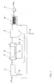
- FIG. 1 is a schematic diagram for explaining the process sequence for obtaining water to be taken from wastewater according to the prior art. This is how to cleanse Wastewater is usually first fed to a primary clarifier 10, in which a mechanical Separation of the finest particles takes place. At the bottom of the pool, substances deposited form a so-called primary sludge, which is withdrawn via a line 12 and a digestion tank is supplied. From the primary clarifier, the wastewater reaches a Aeration tank 14, in which a biological wastewater treatment takes place. This one Aerobic is performed, located in the bottom region of the basin 14 aerator 16, through which compressed air is supplied to the wastewater. Further, a stirrer 18 for Mixing of the wastewater in the aeration tank 14 may be present. About a line Further, a partial flow for denitrification may be returned to the basin 14 become.
- a basin 22 is present in which a slowing down of the flow rate the sewage takes place, whereby a sedimentation of settleable substances takes place. It there is a separation between purified water and activated sludge, with over a Line 24 return sludge biological treatment (activated sludge tank 14) returned becomes. Remaining sludge, like the primary sludge, is sent via a conduit 26 supplied to a digester. The purified from the activated sludge water is finally subjected to filtration. For this purpose, a bed 28 made of quartz sand can be used. Then takes place in a treatment stage 30 disinfecting z. B. with UV radiation.
- the invention provides that after a primary treatment in an im In connection with the pretreatment basin 10 described in FIG. 1, a biological purification in a fluidized bed reactor 32, from which the biologically purified wastewater either directly to a microsieve stage 34 or a so-called lamella separator thickener space 36 from the brochure "The Passavant Turbo LME Method", D-65322 Aarbergen, 2/2000, is known.
- the lamella separator thickener space 36 includes several flocculation 38, in the flocculant or Polyelectrolyte is added. After the flocculation stages is a lamellar separator 40th switched to supply from a drain 42, the water of the microsieve stage 34.
- the lamellar separator 40 is arranged above a thickener space 44. At the Bottom of the thickener space 44 accumulated sludge is either via a pipe 46 fed back as contact sludge a flocculation or - like the primary sludge - Via a line 48 a digester.
- the micro-sieving in the stage 34 takes place in a drum 50, which is in a concrete chamber or mounted in a sheet steel basin.
- the raw water flows through the bearing on the inlet side into the interior of the drum and flows through the rotating drum cage of inside out.
- the peripheral wall of the drum 50 is composed in particular of individual Sieve baskets together, preferably a steel fabric with opening widths between 20 microns and 40 microns.
- the sieve drum 50 is rotated in the filtrate, with a Upper section outside the filtrate runs. At the emergence of the screen body the filtrate running back or falling of adhering to the mesh fabrics contaminants To prevent blade shovels are provided.
- the on the inside of the mesh Retained particles are the circulation of the flat arched screen body in the vertex the drum above the liquid level hosed from outside to inside.
- the particles fall into an inner drainage channel and get through from there an axial flow discharged into a waste water collection channel 56.
- the spray of the screenings takes place with a water pressure of 4.0 to 6.0 bar over a spray water pipe, which can be equipped with high-performance flat jet nozzles. As cleaning water Filtrate is used.
- the pure water line is done either via an overflow edge 55, a fine adjustment allowed to the respective hydraulic conditions, or through slots in the peripheral wall the container 54.
- the captured from the drum 50 cleaning water with the particles is on the Line 56 returned to the primary treatment.
- disinfection preferably takes place by means of UV radiation.
- the corresponding treatment stage is identified by the reference numeral 52.
- the fluidized bed reactor 32 contains filler 60 having a specific surface area, preferably in the range between 800 m 2 / m 3 and 1200 m 2 / m 3 .
- the material for the packing is in particular plastic with a density between 0.85 g / cm 3 and 0.99 g / cm 3 in question.
- ventilation bodies 62 via which compressed air is introduced into the reactor 32 to the required extent.
- a stirrer 64 is further provided for mixing the waste water.
- Liquid or settled solids are further supplied via a line 66 of the pre-treatment. There is a recirculation. This results in the advantage that the micro-sieving is not - as in conventional methods - charged with a high TS concentration, so that increases the cleaning performance. If necessary, it would then be possible to dispense with disinfection.
Landscapes
- Chemical & Material Sciences (AREA)
- Chemical Kinetics & Catalysis (AREA)
- Life Sciences & Earth Sciences (AREA)
- Hydrology & Water Resources (AREA)
- Engineering & Computer Science (AREA)
- Environmental & Geological Engineering (AREA)
- Water Supply & Treatment (AREA)
- Organic Chemistry (AREA)
- Biodiversity & Conservation Biology (AREA)
- Microbiology (AREA)
- Biological Treatment Of Waste Water (AREA)
- Physical Water Treatments (AREA)
Abstract
Description
- Fig. 1
- eine Prinzipdarstellung zur Erläuterung eines üblichen Verfahrens zur Wassergewinnung aus Abwasser,
- Fig. 2
- eine Prinzipdarstellung einer ersten Ausführungsform der erfindungsgemäßen Lehre zur Durchführung eines Verfahrens zur Wassergewinnung aus Abwasser und
- Fig. 3
- eine alternative Ausführungsform zu der der Fig. 2 zu entnehmenden.
Claims (11)
- Verfahren zur Wassergewinnung aus Abwasser, wobei das Abwasser einer Vorklärung, in einer Zwischenstufe einer biologischen Abwasserreinigung, einer Nachklärung und sodann einer Desinfizierung unterzogen wird,
dadurch gekennzeichnet, dass die biologische Abwasserreinigung in der Zwischenstufe in einem Wirbelbettreaktor und die Nachklärung mittels einer Mikrosiebung durchgeführt werden, von der aus das gereinigte Wasser unmittelbar desinfiziert wird. - Verfahren nach Anspruch 1,
dadurch gekennzeichnet, dass das Abwasser in der Vorklärung eine oder mehrere Flockungsstufen und sodann einen Lamellenabscheider durchströmt und anschließend dem Wirbelbettreaktor zugeführt wird. - Verfahren nach Anspruch 1 oder 2,
dadurch gekennzeichnet, dass das Abwasser vor der Mikrosiebung und nach der biologischen Abwasserreinigung eine oder mehrere Flockungsstufen und sodann einen Lamellenabscheider durchströmt. - Verfahren nach zumindest einem der vorhergehenden Ansprüche,
dadurch gekennzeichnet, dass in dem Wirbelbettreaktor Füllmaterial mit einer spezifischen Oberfläche > 700 m2/m3, vorzugsweise zwischen 800 m2/m3 und 1200 m2/m3 eingesetzt wird. - Verfahren nach zumindest einem der vorhergehenden Ansprüche,
dadurch gekennzeichnet, dass als Füllmaterial Körper mit der Dichte ρ mit 0,85 g/cm3 ≤ ρ ≤ 0,99 g/cm3 verwendet wird. - Verfahren nach zumindest einem der vorhergehenden Ansprüche,
dadurch gekennzeichnet, dass das Füllmaterial aus Kunststoff besteht. - Verfahren nach zumindest einem der vorhergehenden Ansprüche,
dadurch gekennzeichnet, dass das Abwasser zur Mikrosiebung ein Stahlgewebe mit Öffnungsweiten zwischen 20 µm und 40 µm durchströmt. - Verfahren nach zumindest einem der vorhergehenden Ansprüche,
dadurch gekennzeichnet, dass die Mikrosiebung in einer umfangsseitig das Stahlgewebe aufweisenden Trommel erfolgt, in deren Inneres das zu reinigende Abwasser einströmt und sodann das Stahlgewebe durchsetzt. - Verfahren nach zumindest einem der vorhergehenden Ansprüche,
dadurch gekennzeichnet, dass Abwasser mit einem Feststoffgehalt < 150 mg/l, insbesondere < 100 mg/l der Mikrosiebung zugeführt wird. - Verfahren nach zumindest einem der vorhergehenden Ansprüche,
dadurch gekennzeichnet, dass das Abwasser unmittelbar nach der Mikrosiebung mit UV-Strahlung desinfiziert wird. - Verfahren nach zumindest einem der vorhergehenden Ansprüche,
dadurch gekennzeichnet, dass ein Teil von in dem Wirbelbettreaktor vorhandenem Abwasser in die Vorklärung zurückgeführt wird.
Priority Applications (3)
| Application Number | Priority Date | Filing Date | Title |
|---|---|---|---|
| SI200530593T SI1584606T1 (sl) | 2004-03-09 | 2005-03-09 | Postopek za biološko rekuperacijo vode iz odpadne vode s pomočjo reaktorja s fluidiziranim slojem |
| PL05005114T PL1584606T3 (pl) | 2004-03-09 | 2005-03-09 | Sposób biologicznego odzyskiwania wody ze ścieków za pomocą reaktora ze złożem fluidalnym |
| CY091100187T CY1108811T1 (el) | 2004-03-09 | 2009-02-18 | Μεθοδος για τη βιολογικη ανακτηση νερου απο λυματα με τη βοηθεια αντιδραστηρα ρευστοποιημενης κλινης |
Applications Claiming Priority (6)
| Application Number | Priority Date | Filing Date | Title |
|---|---|---|---|
| DE102004011849 | 2004-03-09 | ||
| DE102004011849 | 2004-03-09 | ||
| DE102004015470 | 2004-03-26 | ||
| DE102004015470 | 2004-03-26 | ||
| DE200410020235 DE102004020235A1 (de) | 2004-03-09 | 2004-04-22 | Verfahren zur Wassergewinnung aus Abwasser |
| DE102004020235 | 2004-04-22 |
Publications (2)
| Publication Number | Publication Date |
|---|---|
| EP1584606A1 true EP1584606A1 (de) | 2005-10-12 |
| EP1584606B1 EP1584606B1 (de) | 2008-11-19 |
Family
ID=34915874
Family Applications (1)
| Application Number | Title | Priority Date | Filing Date |
|---|---|---|---|
| EP20050005114 Expired - Lifetime EP1584606B1 (de) | 2004-03-09 | 2005-03-09 | Verfahren zur biologischen Wassergewinnung aus Abwasser mit Hilfe eines Wirbelbettreaktors |
Country Status (6)
| Country | Link |
|---|---|
| EP (1) | EP1584606B1 (de) |
| AT (1) | ATE414678T1 (de) |
| CY (1) | CY1108811T1 (de) |
| DE (2) | DE102004020235A1 (de) |
| PL (1) | PL1584606T3 (de) |
| SI (1) | SI1584606T1 (de) |
Cited By (5)
| Publication number | Priority date | Publication date | Assignee | Title |
|---|---|---|---|---|
| EP1893534A4 (de) * | 2005-07-06 | 2008-09-03 | Siemens Water Tech Holdg Corp | Verbessertes phosphorentfernungssystem und -verfahren |
| WO2012001136A1 (fr) * | 2010-07-02 | 2012-01-05 | Veolia Water Solutions & Technologies Support | Dispositif de traitement d'eau comprenant un tambour filtrant plein |
| EP2722089A1 (de) * | 2012-10-22 | 2014-04-23 | Krones AG | Vorrichtung zur thermischen Behandlung von Produkten mit Reinigung der Prozessflüssigkeit |
| GB2575372A (en) * | 2019-08-30 | 2020-01-08 | Lee Ashwell Sean | Water treatment apparatus and method |
| GB2590304A (en) * | 2019-08-30 | 2021-06-23 | Lee Ashwell Sean | Water treatment apparatus and method |
Families Citing this family (1)
| Publication number | Priority date | Publication date | Assignee | Title |
|---|---|---|---|---|
| CN102115288A (zh) * | 2011-01-28 | 2011-07-06 | 吴紫城 | 洗车和洗衣废水循环使用处理方法及其设备 |
Citations (5)
| Publication number | Priority date | Publication date | Assignee | Title |
|---|---|---|---|---|
| JPH04200697A (ja) * | 1990-11-30 | 1992-07-21 | Hitachi Chem Co Ltd | 有機性廃水の処理装置 |
| DE4326603A1 (de) * | 1993-08-07 | 1995-02-09 | Kummer Karl Dankwart Dipl Ing | Kläranlage mit Belebungsbecken |
| WO1997028093A1 (de) * | 1996-01-30 | 1997-08-07 | E.V.U. Entwicklung Von Umwelttechnik Gmbh | Biologische kleinkläranlage |
| DE10105221A1 (de) * | 2001-02-02 | 2002-08-08 | Koch Dietz Peter | Verfahren und Vorrichtung zur Elimination unerwünschter Wasserinhaltsstoffe |
| US20030201225A1 (en) * | 2002-04-30 | 2003-10-30 | Josse Juan Carlos | Organic slurry treatment process |
Family Cites Families (7)
| Publication number | Priority date | Publication date | Assignee | Title |
|---|---|---|---|---|
| DE2505565A1 (de) * | 1975-02-10 | 1976-08-26 | Zell I W J Krueckels Maschf | Verfahren zum sieben einer fluessigkeit, und vorrichtung zum durchfuehren eines solchen verfahrens |
| DE3243817C2 (de) * | 1982-11-26 | 1986-01-02 | Hager & Elsässer GmbH, 7000 Stuttgart | Verfahren zur Erzeugung von keimarmem Reinwasser |
| AT392460B (de) * | 1986-11-20 | 1991-04-10 | Waagner Biro Ag | Verfahren zum biologischen reinigen von abwasser |
| DE3827715A1 (de) * | 1988-08-16 | 1990-02-22 | Metz Mannheim Gmbh | Einrichtung und verfahren zur mikrobiologischen wasseraufbereitung |
| DE4205572A1 (de) * | 1992-02-24 | 1993-08-26 | Linde Ag | Verfahren und reaktionsteilchen zur durchfuehrung von reaktionen |
| DE19520542C2 (de) * | 1995-06-06 | 1999-02-18 | Eisenmann Kg Maschbau | Verfahren zur biologischen Behandlung von Abwasser und Anlage zur Verfahrensdurchführung |
| DE20209891U1 (de) * | 2002-06-26 | 2002-11-07 | 3F GmbH & Co. KG, 07368 Ebersdorf | F1 Mikrobenaufwuchselement zur Wasser- und Abwasserreinigung |
-
2004
- 2004-04-22 DE DE200410020235 patent/DE102004020235A1/de not_active Withdrawn
-
2005
- 2005-03-09 AT AT05005114T patent/ATE414678T1/de not_active IP Right Cessation
- 2005-03-09 EP EP20050005114 patent/EP1584606B1/de not_active Expired - Lifetime
- 2005-03-09 PL PL05005114T patent/PL1584606T3/pl unknown
- 2005-03-09 SI SI200530593T patent/SI1584606T1/sl unknown
- 2005-03-09 DE DE200550005979 patent/DE502005005979D1/de not_active Expired - Lifetime
-
2009
- 2009-02-18 CY CY091100187T patent/CY1108811T1/el unknown
Patent Citations (5)
| Publication number | Priority date | Publication date | Assignee | Title |
|---|---|---|---|---|
| JPH04200697A (ja) * | 1990-11-30 | 1992-07-21 | Hitachi Chem Co Ltd | 有機性廃水の処理装置 |
| DE4326603A1 (de) * | 1993-08-07 | 1995-02-09 | Kummer Karl Dankwart Dipl Ing | Kläranlage mit Belebungsbecken |
| WO1997028093A1 (de) * | 1996-01-30 | 1997-08-07 | E.V.U. Entwicklung Von Umwelttechnik Gmbh | Biologische kleinkläranlage |
| DE10105221A1 (de) * | 2001-02-02 | 2002-08-08 | Koch Dietz Peter | Verfahren und Vorrichtung zur Elimination unerwünschter Wasserinhaltsstoffe |
| US20030201225A1 (en) * | 2002-04-30 | 2003-10-30 | Josse Juan Carlos | Organic slurry treatment process |
Non-Patent Citations (1)
| Title |
|---|
| PATENT ABSTRACTS OF JAPAN vol. 016, no. 533 (C - 1002) 4 November 1992 (1992-11-04) * |
Cited By (13)
| Publication number | Priority date | Publication date | Assignee | Title |
|---|---|---|---|---|
| US7670486B2 (en) | 2005-07-06 | 2010-03-02 | Siemens Water Technologies Corp. | Phosphorus removal system and process |
| US8017018B2 (en) | 2005-07-06 | 2011-09-13 | Siemens Industry, Inc. | Phosphorus removal method |
| US8101072B2 (en) | 2005-07-06 | 2012-01-24 | Siemens Industry, Inc. | Phosphorous removal system |
| EP1893534A4 (de) * | 2005-07-06 | 2008-09-03 | Siemens Water Tech Holdg Corp | Verbessertes phosphorentfernungssystem und -verfahren |
| AU2011273397B2 (en) * | 2010-07-02 | 2015-04-02 | Veolia Water Solutions & Technolgies Support | Device for treating water comprising a solid filter drum |
| WO2012001136A1 (fr) * | 2010-07-02 | 2012-01-05 | Veolia Water Solutions & Technologies Support | Dispositif de traitement d'eau comprenant un tambour filtrant plein |
| FR2962049A1 (fr) * | 2010-07-02 | 2012-01-06 | Veolia Water Solutions & Tech | Dispositif de traitement d'eau comprenant un tambour filtrant plein |
| EP2722089A1 (de) * | 2012-10-22 | 2014-04-23 | Krones AG | Vorrichtung zur thermischen Behandlung von Produkten mit Reinigung der Prozessflüssigkeit |
| CN103768622A (zh) * | 2012-10-22 | 2014-05-07 | 克朗斯股份公司 | 用于热处理容器中的产品的装置及分离单元的使用 |
| EP2722089B1 (de) | 2012-10-22 | 2015-04-29 | Krones AG | Vorrichtung zur thermischen Behandlung von Produkten mit Reinigung der Prozessflüssigkeit |
| GB2575372A (en) * | 2019-08-30 | 2020-01-08 | Lee Ashwell Sean | Water treatment apparatus and method |
| GB2575372B (en) * | 2019-08-30 | 2021-04-14 | Lee Ashwell Sean | Water treatment apparatus and method |
| GB2590304A (en) * | 2019-08-30 | 2021-06-23 | Lee Ashwell Sean | Water treatment apparatus and method |
Also Published As
| Publication number | Publication date |
|---|---|
| EP1584606B1 (de) | 2008-11-19 |
| SI1584606T1 (sl) | 2009-04-30 |
| PL1584606T3 (pl) | 2009-04-30 |
| DE502005005979D1 (de) | 2009-01-02 |
| ATE414678T1 (de) | 2008-12-15 |
| CY1108811T1 (el) | 2014-04-09 |
| DE102004020235A1 (de) | 2005-09-29 |
Similar Documents
| Publication | Publication Date | Title |
|---|---|---|
| DE69413704T2 (de) | Verfahren und apparat zur wassergewinnung aus einem vorfluter | |
| DE60104188T2 (de) | Verfahren und vorrichtung zur behandlung von wasser/abwasser | |
| AT412275B (de) | Biologische reinigung von wasser | |
| DE2739690A1 (de) | Verfahren und vorrichtung zum reinigen von abwaessern | |
| DE102008030809B4 (de) | Verfahren und Vorrichtung zur Wasserrückgewinnung bzw. zur Reinigung von Abwasser | |
| DE102013009392A1 (de) | Wasseraufbereitung für die Fischzucht | |
| EP1584606B1 (de) | Verfahren zur biologischen Wassergewinnung aus Abwasser mit Hilfe eines Wirbelbettreaktors | |
| DE19845808C1 (de) | Verfahren und Vorrichtung zur biologischen Reinigung von Abwasser | |
| EP2225012B1 (de) | Abwasserbehandlungsanlage und verfahren zum behandeln von abwasser | |
| EP1568662B1 (de) | Membranbioreaktor und Verfahren zur Reinigung von Abwässern | |
| DE102008049970A1 (de) | Verfahren und Vorrichtung zur Aufbereitung von Grauwasser | |
| DE2630118A1 (de) | Verfahren und vorrichtung zur abwasserreinigung | |
| WO2018087384A1 (de) | Aufbereitung von abwasser zu trinkwasser mittels ozon | |
| EP1265819B1 (de) | Verfahren und vorrichtung zur abwasserreinigung | |
| CH637905A5 (en) | Process and equipment for effluent treatment | |
| DE60015557T2 (de) | Verfahren und anordnung zur reinigung von wasser | |
| EP0686605B1 (de) | Verfahren zur biologischen Reinigung von organisch belasteten Abwässern | |
| DE10059839C2 (de) | Verfahren und Vorrichtung zur Schlammeindickung in mechanisch-biologischen Abwasser-Kläranlagen | |
| EP2046689B8 (de) | Anlage zur vorreinigung von schmutzwässern mit integrierter weiterbehandlung der feststoffe | |
| DE102009049540A1 (de) | Anlage und Verfahren zur Wiederaufbereitung von Grauwasser | |
| Côté et al. | Pretreatment requirements for membrane bioreactors | |
| DE102004033152B4 (de) | Reinigungssystem zur Herstellung dauerhaft naturnaher Wässer | |
| DE10105221A1 (de) | Verfahren und Vorrichtung zur Elimination unerwünschter Wasserinhaltsstoffe | |
| EP1714946A2 (de) | Vorrichtung und Verfahren zum biologischen Aufbereiten von Abwasser | |
| WO2006002619A1 (de) | Reinigungssystem zur herstellung dauerhaft naturnaher wässer |
Legal Events
| Date | Code | Title | Description |
|---|---|---|---|
| PUAI | Public reference made under article 153(3) epc to a published international application that has entered the european phase |
Free format text: ORIGINAL CODE: 0009012 |
|
| AK | Designated contracting states |
Kind code of ref document: A1 Designated state(s): AT BE BG CH CY CZ DE DK EE ES FI FR GB GR HU IE IS IT LI LT LU MC NL PL PT RO SE SI SK TR |
|
| AX | Request for extension of the european patent |
Extension state: AL BA HR LV MK YU |
|
| 17P | Request for examination filed |
Effective date: 20060128 |
|
| AKX | Designation fees paid |
Designated state(s): AT BE BG CH CY CZ DE DK EE ES FI FR GB GR HU IE IS IT LI LT LU MC NL PL PT RO SE SI SK TR |
|
| AXX | Extension fees paid |
Extension state: LV Payment date: 20060128 |
|
| GRAP | Despatch of communication of intention to grant a patent |
Free format text: ORIGINAL CODE: EPIDOSNIGR1 |
|
| GRAS | Grant fee paid |
Free format text: ORIGINAL CODE: EPIDOSNIGR3 |
|
| GRAA | (expected) grant |
Free format text: ORIGINAL CODE: 0009210 |
|
| AK | Designated contracting states |
Kind code of ref document: B1 Designated state(s): AT BE BG CH CY CZ DE DK EE ES FI FR GB GR HU IE IS IT LI LT LU MC NL PL PT RO SE SI SK TR |
|
| AX | Request for extension of the european patent |
Extension state: LV |
|
| REG | Reference to a national code |
Ref country code: GB Ref legal event code: FG4D Free format text: NOT ENGLISH |
|
| REG | Reference to a national code |
Ref country code: CH Ref legal event code: EP |
|
| REG | Reference to a national code |
Ref country code: IE Ref legal event code: FG4D Free format text: LANGUAGE OF EP DOCUMENT: GERMAN |
|
| REF | Corresponds to: |
Ref document number: 502005005979 Country of ref document: DE Date of ref document: 20090102 Kind code of ref document: P |
|
| REG | Reference to a national code |
Ref country code: RO Ref legal event code: EPE |
|
| REG | Reference to a national code |
Ref country code: GR Ref legal event code: EP Ref document number: 20090400510 Country of ref document: GR |
|
| RAP2 | Party data changed (patent owner data changed or rights of a patent transferred) |
Owner name: BILFINGER BERGER UMWELTTECHNIK GMBH |
|
| PG25 | Lapsed in a contracting state [announced via postgrant information from national office to epo] |
Ref country code: ES Free format text: LAPSE BECAUSE OF FAILURE TO SUBMIT A TRANSLATION OF THE DESCRIPTION OR TO PAY THE FEE WITHIN THE PRESCRIBED TIME-LIMIT Effective date: 20090301 |
|
| PGFP | Annual fee paid to national office [announced via postgrant information from national office to epo] |
Ref country code: HU Payment date: 20090309 Year of fee payment: 5 Ref country code: LT Payment date: 20090224 Year of fee payment: 5 |
|
| REG | Reference to a national code |
Ref country code: PL Ref legal event code: T3 |
|
| NLV1 | Nl: lapsed or annulled due to failure to fulfill the requirements of art. 29p and 29m of the patents act | ||
| PG25 | Lapsed in a contracting state [announced via postgrant information from national office to epo] |
Ref country code: IS Free format text: LAPSE BECAUSE OF FAILURE TO SUBMIT A TRANSLATION OF THE DESCRIPTION OR TO PAY THE FEE WITHIN THE PRESCRIBED TIME-LIMIT Effective date: 20090319 Ref country code: NL Free format text: LAPSE BECAUSE OF FAILURE TO SUBMIT A TRANSLATION OF THE DESCRIPTION OR TO PAY THE FEE WITHIN THE PRESCRIBED TIME-LIMIT Effective date: 20081119 Ref country code: FI Free format text: LAPSE BECAUSE OF FAILURE TO SUBMIT A TRANSLATION OF THE DESCRIPTION OR TO PAY THE FEE WITHIN THE PRESCRIBED TIME-LIMIT Effective date: 20081119 |
|
| PGFP | Annual fee paid to national office [announced via postgrant information from national office to epo] |
Ref country code: CZ Payment date: 20090304 Year of fee payment: 5 Ref country code: PL Payment date: 20090219 Year of fee payment: 5 Ref country code: RO Payment date: 20090227 Year of fee payment: 5 Ref country code: SI Payment date: 20090225 Year of fee payment: 5 |
|
| REG | Reference to a national code |
Ref country code: HU Ref legal event code: AG4A Ref document number: E005022 Country of ref document: HU |
|
| REG | Reference to a national code |
Ref country code: IE Ref legal event code: FD4D |
|
| PG25 | Lapsed in a contracting state [announced via postgrant information from national office to epo] |
Ref country code: IE Free format text: LAPSE BECAUSE OF FAILURE TO SUBMIT A TRANSLATION OF THE DESCRIPTION OR TO PAY THE FEE WITHIN THE PRESCRIBED TIME-LIMIT Effective date: 20081119 Ref country code: DK Free format text: LAPSE BECAUSE OF FAILURE TO SUBMIT A TRANSLATION OF THE DESCRIPTION OR TO PAY THE FEE WITHIN THE PRESCRIBED TIME-LIMIT Effective date: 20081119 |
|
| PGFP | Annual fee paid to national office [announced via postgrant information from national office to epo] |
Ref country code: BG Payment date: 20090331 Year of fee payment: 5 Ref country code: EE Payment date: 20090223 Year of fee payment: 5 |
|
| PG25 | Lapsed in a contracting state [announced via postgrant information from national office to epo] |
Ref country code: SE Free format text: LAPSE BECAUSE OF FAILURE TO SUBMIT A TRANSLATION OF THE DESCRIPTION OR TO PAY THE FEE WITHIN THE PRESCRIBED TIME-LIMIT Effective date: 20090219 Ref country code: PT Free format text: LAPSE BECAUSE OF FAILURE TO SUBMIT A TRANSLATION OF THE DESCRIPTION OR TO PAY THE FEE WITHIN THE PRESCRIBED TIME-LIMIT Effective date: 20090420 |
|
| PLBE | No opposition filed within time limit |
Free format text: ORIGINAL CODE: 0009261 |
|
| STAA | Information on the status of an ep patent application or granted ep patent |
Free format text: STATUS: NO OPPOSITION FILED WITHIN TIME LIMIT |
|
| BERE | Be: lapsed |
Owner name: PASSAVANT-ROEDIGER UMWELTTECHNIK G.M.B.H. Effective date: 20090331 |
|
| PGFP | Annual fee paid to national office [announced via postgrant information from national office to epo] |
Ref country code: SK Payment date: 20090302 Year of fee payment: 5 |
|
| 26N | No opposition filed |
Effective date: 20090820 |
|
| PG25 | Lapsed in a contracting state [announced via postgrant information from national office to epo] |
Ref country code: MC Free format text: LAPSE BECAUSE OF NON-PAYMENT OF DUE FEES Effective date: 20090331 |
|
| REG | Reference to a national code |
Ref country code: CH Ref legal event code: PL |
|
| GBPC | Gb: european patent ceased through non-payment of renewal fee |
Effective date: 20090309 |
|
| REG | Reference to a national code |
Ref country code: EE Ref legal event code: GB1A Ref document number: E003099 Country of ref document: EE |
|
| REG | Reference to a national code |
Ref country code: FR Ref legal event code: ST Effective date: 20091130 |
|
| REG | Reference to a national code |
Ref country code: HU Ref legal event code: GB9C Owner name: PASSAVANT-ROEDIGER GMBH, DE Free format text: FORMER OWNER(S): BILFINGER BERGER UMWELTTECHNIK GMBH, DE Ref country code: HU Ref legal event code: FH1C Free format text: FORMER REPRESENTATIVE(S): SCHL?FER LASZLO, DANUBIA SZABADALMI ES JOGI IRODA KFT., HU Representative=s name: DANUBIA SZABADALMI ES JOGI IRODA KFT., HU |
|
| PG25 | Lapsed in a contracting state [announced via postgrant information from national office to epo] |
Ref country code: CH Free format text: LAPSE BECAUSE OF NON-PAYMENT OF DUE FEES Effective date: 20090331 Ref country code: LI Free format text: LAPSE BECAUSE OF NON-PAYMENT OF DUE FEES Effective date: 20090331 |
|
| PG25 | Lapsed in a contracting state [announced via postgrant information from national office to epo] |
Ref country code: BE Free format text: LAPSE BECAUSE OF NON-PAYMENT OF DUE FEES Effective date: 20090331 |
|
| REG | Reference to a national code |
Ref country code: SI Ref legal event code: SP73 Owner name: PASSAVANT-ROEDIGER GMBH; DE Effective date: 20100216 |
|
| PG25 | Lapsed in a contracting state [announced via postgrant information from national office to epo] |
Ref country code: FR Free format text: LAPSE BECAUSE OF NON-PAYMENT OF DUE FEES Effective date: 20091123 Ref country code: GB Free format text: LAPSE BECAUSE OF NON-PAYMENT OF DUE FEES Effective date: 20090309 |
|
| PG25 | Lapsed in a contracting state [announced via postgrant information from national office to epo] |
Ref country code: AT Free format text: LAPSE BECAUSE OF NON-PAYMENT OF DUE FEES Effective date: 20090309 |
|
| REG | Reference to a national code |
Ref country code: SK Ref legal event code: PC4A Ref document number: E 5011 Country of ref document: SK Owner name: PASSAVANT-ROEDIGER GMBH, HANAU, DE Free format text: FORMER OWNER: BILFINGER BERGER UMWELTTECHNIK GMBH, AARBERGEN, DE Effective date: 20100720 |
|
| LTLA | Lt: lapse of european patent or patent extension |
Effective date: 20100309 |
|
| PG25 | Lapsed in a contracting state [announced via postgrant information from national office to epo] |
Ref country code: LT Free format text: LAPSE BECAUSE OF NON-PAYMENT OF DUE FEES Effective date: 20100309 |
|
| PG25 | Lapsed in a contracting state [announced via postgrant information from national office to epo] |
Ref country code: CZ Free format text: LAPSE BECAUSE OF NON-PAYMENT OF DUE FEES Effective date: 20100309 |
|
| REG | Reference to a national code |
Ref country code: SI Ref legal event code: KO00 Effective date: 20101015 |
|
| REG | Reference to a national code |
Ref country code: SK Ref legal event code: MM4A Ref document number: E 5011 Country of ref document: SK Effective date: 20100309 |
|
| REG | Reference to a national code |
Ref country code: EE Ref legal event code: MM4A Ref document number: E003099 Country of ref document: EE Effective date: 20100331 |
|
| PG25 | Lapsed in a contracting state [announced via postgrant information from national office to epo] |
Ref country code: EE Free format text: LAPSE BECAUSE OF NON-PAYMENT OF DUE FEES Effective date: 20100331 |
|
| PG25 | Lapsed in a contracting state [announced via postgrant information from national office to epo] |
Ref country code: SK Free format text: LAPSE BECAUSE OF NON-PAYMENT OF DUE FEES Effective date: 20100309 Ref country code: SI Free format text: LAPSE BECAUSE OF NON-PAYMENT OF DUE FEES Effective date: 20100310 Ref country code: HU Free format text: LAPSE BECAUSE OF NON-PAYMENT OF DUE FEES Effective date: 20100310 Ref country code: BG Free format text: LAPSE BECAUSE OF NON-PAYMENT OF DUE FEES Effective date: 20101031 |
|
| PG25 | Lapsed in a contracting state [announced via postgrant information from national office to epo] |
Ref country code: IT Free format text: LAPSE BECAUSE OF FAILURE TO SUBMIT A TRANSLATION OF THE DESCRIPTION OR TO PAY THE FEE WITHIN THE PRESCRIBED TIME-LIMIT Effective date: 20081119 |
|
| PG25 | Lapsed in a contracting state [announced via postgrant information from national office to epo] |
Ref country code: LU Free format text: LAPSE BECAUSE OF NON-PAYMENT OF DUE FEES Effective date: 20090309 |
|
| PGFP | Annual fee paid to national office [announced via postgrant information from national office to epo] |
Ref country code: GR Payment date: 20110330 Year of fee payment: 7 |
|
| PG25 | Lapsed in a contracting state [announced via postgrant information from national office to epo] |
Ref country code: RO Free format text: LAPSE BECAUSE OF NON-PAYMENT OF DUE FEES Effective date: 20100309 |
|
| PGFP | Annual fee paid to national office [announced via postgrant information from national office to epo] |
Ref country code: CY Payment date: 20110223 Year of fee payment: 7 |
|
| REG | Reference to a national code |
Ref country code: PL Ref legal event code: LAPE |
|
| PG25 | Lapsed in a contracting state [announced via postgrant information from national office to epo] |
Ref country code: PL Free format text: LAPSE BECAUSE OF NON-PAYMENT OF DUE FEES Effective date: 20100309 |
|
| PGFP | Annual fee paid to national office [announced via postgrant information from national office to epo] |
Ref country code: DE Payment date: 20120321 Year of fee payment: 8 Ref country code: TR Payment date: 20120308 Year of fee payment: 8 |
|
| PG25 | Lapsed in a contracting state [announced via postgrant information from national office to epo] |
Ref country code: CY Free format text: LAPSE BECAUSE OF NON-PAYMENT OF DUE FEES Effective date: 20120309 |
|
| REG | Reference to a national code |
Ref country code: GR Ref legal event code: ML Ref document number: 20090400510 Country of ref document: GR Effective date: 20121008 |
|
| PG25 | Lapsed in a contracting state [announced via postgrant information from national office to epo] |
Ref country code: GR Free format text: LAPSE BECAUSE OF NON-PAYMENT OF DUE FEES Effective date: 20121008 |
|
| REG | Reference to a national code |
Ref country code: DE Ref legal event code: R119 Ref document number: 502005005979 Country of ref document: DE Effective date: 20131001 |
|
| PG25 | Lapsed in a contracting state [announced via postgrant information from national office to epo] |
Ref country code: DE Free format text: LAPSE BECAUSE OF NON-PAYMENT OF DUE FEES Effective date: 20131001 |
|
| PG25 | Lapsed in a contracting state [announced via postgrant information from national office to epo] |
Ref country code: TR Free format text: LAPSE BECAUSE OF NON-PAYMENT OF DUE FEES Effective date: 20130309 |