EP1584786A2 - Aube statorique à haute efficacité pour la deuxième étage d' une turbine à gaz - Google Patents
Aube statorique à haute efficacité pour la deuxième étage d' une turbine à gaz Download PDFInfo
- Publication number
- EP1584786A2 EP1584786A2 EP05252177A EP05252177A EP1584786A2 EP 1584786 A2 EP1584786 A2 EP 1584786A2 EP 05252177 A EP05252177 A EP 05252177A EP 05252177 A EP05252177 A EP 05252177A EP 1584786 A2 EP1584786 A2 EP 1584786A2
- Authority
- EP
- European Patent Office
- Prior art keywords
- blade
- profile
- turbine
- stator
- throat
- Prior art date
- Legal status (The legal status is an assumption and is not a legal conclusion. Google has not performed a legal analysis and makes no representation as to the accuracy of the status listed.)
- Withdrawn
Links
- 239000011248 coating agent Substances 0.000 claims description 4
- 238000000576 coating method Methods 0.000 claims description 4
- 239000007789 gas Substances 0.000 description 27
- 238000002485 combustion reaction Methods 0.000 description 9
- 238000006243 chemical reaction Methods 0.000 description 3
- 239000000446 fuel Substances 0.000 description 3
- 238000010438 heat treatment Methods 0.000 description 3
- 239000012530 fluid Substances 0.000 description 2
- 238000007493 shaping process Methods 0.000 description 2
- 230000006835 compression Effects 0.000 description 1
- 238000007906 compression Methods 0.000 description 1
- 238000001816 cooling Methods 0.000 description 1
- 238000007599 discharging Methods 0.000 description 1
- 238000010309 melting process Methods 0.000 description 1
- 238000000034 method Methods 0.000 description 1
- 239000000203 mixture Substances 0.000 description 1
- 210000000056 organ Anatomy 0.000 description 1
- 230000035882 stress Effects 0.000 description 1
- 238000006467 substitution reaction Methods 0.000 description 1
- 230000008646 thermal stress Effects 0.000 description 1
- 230000009466 transformation Effects 0.000 description 1
- 230000001131 transforming effect Effects 0.000 description 1
Images


Classifications
-
- F—MECHANICAL ENGINEERING; LIGHTING; HEATING; WEAPONS; BLASTING
- F01—MACHINES OR ENGINES IN GENERAL; ENGINE PLANTS IN GENERAL; STEAM ENGINES
- F01D—NON-POSITIVE DISPLACEMENT MACHINES OR ENGINES, e.g. STEAM TURBINES
- F01D9/00—Stators
- F01D9/02—Nozzles; Nozzle boxes; Stator blades; Guide conduits, e.g. individual nozzles
- F01D9/04—Nozzles; Nozzle boxes; Stator blades; Guide conduits, e.g. individual nozzles forming ring or sector
- F01D9/041—Nozzles; Nozzle boxes; Stator blades; Guide conduits, e.g. individual nozzles forming ring or sector using blades
-
- F—MECHANICAL ENGINEERING; LIGHTING; HEATING; WEAPONS; BLASTING
- F01—MACHINES OR ENGINES IN GENERAL; ENGINE PLANTS IN GENERAL; STEAM ENGINES
- F01D—NON-POSITIVE DISPLACEMENT MACHINES OR ENGINES, e.g. STEAM TURBINES
- F01D5/00—Blades; Blade-carrying members; Heating, heat-insulating, cooling or antivibration means on the blades or the members
- F01D5/12—Blades
-
- Y—GENERAL TAGGING OF NEW TECHNOLOGICAL DEVELOPMENTS; GENERAL TAGGING OF CROSS-SECTIONAL TECHNOLOGIES SPANNING OVER SEVERAL SECTIONS OF THE IPC; TECHNICAL SUBJECTS COVERED BY FORMER USPC CROSS-REFERENCE ART COLLECTIONS [XRACs] AND DIGESTS
- Y10—TECHNICAL SUBJECTS COVERED BY FORMER USPC
- Y10S—TECHNICAL SUBJECTS COVERED BY FORMER USPC CROSS-REFERENCE ART COLLECTIONS [XRACs] AND DIGESTS
- Y10S416/00—Fluid reaction surfaces, i.e. impellers
- Y10S416/02—Formulas of curves
Definitions
- the present invention relates to a stator for the second phase of a gas turbine.
- the invention relates to a high aerodynamic efficiency stator for the second phase of a low-pressure gas turbine.
- Gas turbine refers to a rotating thermal machine which converts the enthalpy of a gas into useful work, using gases coming from a combustion and which supplies mechanical power on a rotating shaft.
- the turbine therefore normally comprises a compressor or turbo-compressor, inside which the air taken from the outside is brought under pressure.
- Various injectors feed the fuel which is mixed with the air to form a air-fuel ignition mixture.
- the axial compressor is entrained by a turbine, or more precisely turbo-expander, which supplies mechanical energy to a user transforming the enthalpy of the gases combusted in the combustion chamber.
- the expansion jump is subdivided into two partial jumps, each of which takes place inside a turbine.
- the high-pressure turbine downstream of the combustion chamber, entrains the compression.
- the low-pressure turbine which collects the gases coming from the high-pressure turbine, is then connected to a user.
- turbo-expander turbo-compressor
- combustion chamber or heater
- outlet shaft regulation system and ignition system
- the gas has low-pressure and low-temperature characteristics, whereas, as it passes through the compressor, the gas is compressed and its temperature increases.
- the heat necessary for the temperature increase of the gas is supplied by the combustion of gas fuel introduced into the heating chamber, by means of injectors.
- the triggering of the combustion, when the machine is activated, is obtained by means of sparking plugs.
- the high-pressure and high-temperature gas reaches the turbine, through specific ducts, where it gives up part of the energy accumulated in the compressor and heating chamber (combustor) and then flows outside by means of the discharge channels.
- the phase is therefore the constitutive element for each section of a turbine and comprises a stator and a rotor, each equipped with a series of blades.
- thermodynamic cycle parameters such as combustion temperature, pressure changes, efficacy of the cooling system and components of the turbine.
- the geometrical configuration of the blade system significantly influences the aerodynamic efficiency. This depends on the fact that the geometrical characteristics of the blade determine the distribution of the relative fluid rates, consequently influencing the distribution of the limit layers along the walls and, last but not least, friction losses.
- the overall power of the gas turbine is related not only to the efficiency of the turbine itself, but also to the gas flow-rate which it can dispose of.
- a power increase can therefore be obtained by increasing the gas flow-rate which is it capable of processing.
- One of the objectives of the present invention is therefore to provide a stator for the second phase of a low-pressure turbine which, being the same the dimensions of the turbine, increases the power of the turbine itself.
- Another objective of the present invention is to provide a stator for the second step of a low-pressure turbine which allows a high aerodynamic efficiency and at the same time enables a high flow-rate of the turbine to be obtained, with a consequent increase in the power of the turbine itself with the same turbine dimensions.
- a further objective of the present invention is to provide a stator for the second phase of a low-pressure turbine which allows a high aerodynamic efficiency.
- Yet another objective of the present invention is to provide a stator for the second phase of a low-pressure turbine which can be produced on a wide scale by means of automated processes.
- a further objective of the present invention is to provide a stator for the second phase of a low-pressure turbine which, through three-dimensional modeling, can be defined by means of a limited series of starting elements.
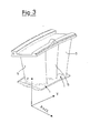
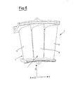
- a stator for a second phase of a gas turbine comprising an outer side surface and a series of blades 1 distributed on the outer side surface of the stator itself.
- Said blades 1 are uniformly distributed on said outer side surface.
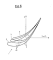
- Each blade 1 is defined by means of coordinates of a discreet combination of points, in a Cartesian reference system X,Y,Z, wherein the axis Z is a radial axis intersecting the central axis of the turbine.
- each blade 1 is identified by means of a series of closed intersection curves 20 between the profile itself and planes X,Y lying at distances Z from the central axis.
- each blade 1 comprises a first concave surface 3, which is under pressure, and a second convex surface 5 which is in depression and which is opposite to the first.
- the two surfaces 3, 5 are continuous and jointly form the profile of each blade 1.
- Each closed curve 20 has a throat angle defined by the cosine arc of the ratio between the length of the throat and the circumferential pitch, evaluated at the radius corresponding to the distance Z from the central axis of the closed curve 20 itself.
- Each blade 1 defines with the adjacent blades, passage sections for a gas, respectively a first inlet section and a throat section through which a gas passes in sequence.
- each throat section of the stator was obtained by suitably varying the throat angle of each closed curve 20.
- Each blade 1 has an average throat angle evaluated at mid-height of the blade 1 itself.
- Said average throat angle preferably ranges from 57.8° to 60.8°.
- Said average throat angle is preferably 59.3°.
- Each blade 1 has a throat angle distribution which varies along the height of the blade 1 itself.
- said throat angle distribution has a shift preferably ranging from +1.5° to -1.5°, so as to reduce the secondary pressure drops to the minimum.
- throat section There is in fact a relation between the throat section and characteristics such as efficiency and useful life of the turbine blades obtained by shaping the blades in relation to the inclination of the throat section itself.
- each blade 1 was suitably shaped to allow the efficiency to be maintained at high levels.
- each blade 1 is also directly influenced by said average throat angle.
- the present invention once the average throat angle has been fixed as also the shift of the throat angle distribution along the height Z of the blade 1, it is possible to shape the profile of each blade 1 so as to maintain a high efficiency and an adequate useful life.
- a stator of a second phase of a gas turbine preferably comprises a series of shaped blades 1, each of which has a shaped aerodynamic profile.
- each blade 1 of the stator for the second low-pressure phase of a gas turbine is defined by means of a series of closed curves 20 whose coordinates are defined with respect to a Cartesian reference system X,Y,Z, wherein the axis Z is a radial axis intersecting the central axis of the turbine, and said closed curves 20 lying at distances Z from the central axis, are defined according to Table I, whose values refer to a room temperature profile and are divided by value, expressed in millimeters, of the axial chord referring to the most internal distance Z of the blade 1, indicated in table 1 with CHX.
- the aerodynamic profile of the blade according to the invention is obtained with the values of Table I by stacking together the series of closed curves 20 and connecting them so as to obtain a continuous aerodynamic profile.
- each blade 1 can have a tolerance of +/- 0.3 mm in a normal direction with respect the profile of the blade 1 itself.
- each blade 1 can also comprise a coating, subsequently applied and such as to vary the profile itself.
- Said anti-wear coating has a thickness defined in a normal direction with respect to each surface of the blade and ranging from 0 to 0.5 mm.
- each blade therefore has an aerodynamic profile which allows a high conversion efficiency and a high useful life to be maintained.
Landscapes
- Engineering & Computer Science (AREA)
- Mechanical Engineering (AREA)
- General Engineering & Computer Science (AREA)
- Turbine Rotor Nozzle Sealing (AREA)
- Organic Low-Molecular-Weight Compounds And Preparation Thereof (AREA)
- Treating Waste Gases (AREA)
- Optical Record Carriers And Manufacture Thereof (AREA)
Applications Claiming Priority (2)
| Application Number | Priority Date | Filing Date | Title |
|---|---|---|---|
| IT000710A ITMI20040710A1 (it) | 2004-04-09 | 2004-04-09 | Statore ad elevata efficienza per secondo stadio di una turbina a gas |
| ITMI20040710 | 2004-04-09 |
Publications (2)
| Publication Number | Publication Date |
|---|---|
| EP1584786A2 true EP1584786A2 (fr) | 2005-10-12 |
| EP1584786A3 EP1584786A3 (fr) | 2011-05-11 |
Family
ID=34897798
Family Applications (1)
| Application Number | Title | Priority Date | Filing Date |
|---|---|---|---|
| EP05252177A Withdrawn EP1584786A3 (fr) | 2004-04-09 | 2005-04-07 | Aube statorique à haute efficacité pour le deuxième étage d' une turbine à gaz |
Country Status (8)
| Country | Link |
|---|---|
| US (1) | US7390165B2 (fr) |
| EP (1) | EP1584786A3 (fr) |
| JP (1) | JP2005299657A (fr) |
| KR (1) | KR101370091B1 (fr) |
| CN (1) | CN100410495C (fr) |
| CA (1) | CA2502788C (fr) |
| IT (1) | ITMI20040710A1 (fr) |
| NO (1) | NO20051740L (fr) |
Cited By (1)
| Publication number | Priority date | Publication date | Assignee | Title |
|---|---|---|---|---|
| EP2692987A4 (fr) * | 2011-03-30 | 2014-08-27 | Mitsubishi Heavy Ind Ltd | Turbine à gaz |
Families Citing this family (19)
| Publication number | Priority date | Publication date | Assignee | Title |
|---|---|---|---|---|
| US8281374B2 (en) * | 2005-09-14 | 2012-10-02 | Oracle International Corporation | Attested identities |
| FR2899269A1 (fr) * | 2006-03-30 | 2007-10-05 | Snecma Sa | Aube de redresseur optimisee, secteur de redresseurs, etage de compression, compresseur et turbomachine comportant une telle aube |
| ITMI20101447A1 (it) * | 2010-07-30 | 2012-01-30 | Alstom Technology Ltd | "turbina a vapore a bassa pressione e metodo per il funzionamento della stessa" |
| US9074483B2 (en) | 2011-03-25 | 2015-07-07 | General Electric Company | High camber stator vane |
| US9157326B2 (en) | 2012-07-02 | 2015-10-13 | United Technologies Corporation | Airfoil for improved flow distribution with high radial offset |
| WO2015112222A2 (fr) * | 2013-11-04 | 2015-07-30 | United Technologies Corporation | Surface portante de moteur à turbines à gaz |
| US9523284B2 (en) * | 2013-11-22 | 2016-12-20 | General Electric Technology Gmbh | Adjusted stationary airfoil |
| US9957805B2 (en) * | 2015-12-18 | 2018-05-01 | General Electric Company | Turbomachine and turbine blade therefor |
| US10443392B2 (en) * | 2016-07-13 | 2019-10-15 | Safran Aircraft Engines | Optimized aerodynamic profile for a turbine vane, in particular for a nozzle of the second stage of a turbine |
| US10443393B2 (en) * | 2016-07-13 | 2019-10-15 | Safran Aircraft Engines | Optimized aerodynamic profile for a turbine vane, in particular for a nozzle of the seventh stage of a turbine |
| US10041503B2 (en) * | 2016-09-30 | 2018-08-07 | General Electric Company | Airfoil shape for ninth stage compressor rotor blade |
| US10066641B2 (en) * | 2016-10-05 | 2018-09-04 | General Electric Company | Airfoil shape for fourth stage compressor stator vane |
| US11466573B1 (en) * | 2021-03-15 | 2022-10-11 | Raytheon Technologies Corporation | Turbine vane |
| CN113217226B (zh) * | 2021-06-02 | 2022-08-02 | 中国航发湖南动力机械研究所 | 桨扇涡轮一体式发动机 |
| US11428159B1 (en) * | 2021-07-01 | 2022-08-30 | Doosan Enerbility Co., Ltd. | Airfoil profile for a turbine blade |
| US11634995B1 (en) * | 2022-09-30 | 2023-04-25 | General Electric Company | Compressor stator vane airfoils |
| US12571323B2 (en) | 2024-06-14 | 2026-03-10 | Pratt & Whitney Canada Corp. | Turbine engine airfoil |
| US12509988B2 (en) | 2024-06-14 | 2025-12-30 | Pratt & Whitney Canada Corp. | Turbine engine airfoil |
| US12345174B1 (en) | 2024-06-14 | 2025-07-01 | Pratt & Whitney Canada Corp. | Turbine engine airfoil |
Citations (3)
| Publication number | Priority date | Publication date | Assignee | Title |
|---|---|---|---|---|
| US5299909A (en) * | 1993-03-25 | 1994-04-05 | Praxair Technology, Inc. | Radial turbine nozzle vane |
| JP2002256810A (ja) * | 2001-03-05 | 2002-09-11 | Toshiba Corp | 軸流タービン |
| JP2003020904A (ja) * | 2001-07-11 | 2003-01-24 | Toshiba Corp | 軸流タービン翼および軸流タービン段落 |
Family Cites Families (10)
| Publication number | Priority date | Publication date | Assignee | Title |
|---|---|---|---|---|
| JPH04269302A (ja) * | 1990-12-06 | 1992-09-25 | Westinghouse Electric Corp <We> | 蒸気タービンの静翼 |
| US5160242A (en) * | 1991-05-31 | 1992-11-03 | Westinghouse Electric Corp. | Freestanding mixed tuned steam turbine blade |
| US5286168A (en) * | 1992-01-31 | 1994-02-15 | Westinghouse Electric Corp. | Freestanding mixed tuned blade |
| US5277549A (en) * | 1992-03-16 | 1994-01-11 | Westinghouse Electric Corp. | Controlled reaction L-2R steam turbine blade |
| US6461110B1 (en) * | 2001-07-11 | 2002-10-08 | General Electric Company | First-stage high pressure turbine bucket airfoil |
| US6474948B1 (en) * | 2001-06-22 | 2002-11-05 | General Electric Company | Third-stage turbine bucket airfoil |
| US6450770B1 (en) * | 2001-06-28 | 2002-09-17 | General Electric Company | Second-stage turbine bucket airfoil |
| US6503059B1 (en) * | 2001-07-06 | 2003-01-07 | General Electric Company | Fourth-stage turbine bucket airfoil |
| US6685434B1 (en) * | 2002-09-17 | 2004-02-03 | General Electric Company | Second stage turbine bucket airfoil |
| US6715990B1 (en) * | 2002-09-19 | 2004-04-06 | General Electric Company | First stage turbine bucket airfoil |
-
2004
- 2004-04-09 IT IT000710A patent/ITMI20040710A1/it unknown
-
2005
- 2005-03-31 CA CA2502788A patent/CA2502788C/fr not_active Expired - Fee Related
- 2005-04-07 KR KR1020050029055A patent/KR101370091B1/ko not_active Expired - Fee Related
- 2005-04-07 US US11/100,625 patent/US7390165B2/en not_active Expired - Fee Related
- 2005-04-07 EP EP05252177A patent/EP1584786A3/fr not_active Withdrawn
- 2005-04-08 JP JP2005111728A patent/JP2005299657A/ja active Pending
- 2005-04-08 NO NO20051740A patent/NO20051740L/no not_active Application Discontinuation
- 2005-04-11 CN CNB2005100641251A patent/CN100410495C/zh not_active Expired - Fee Related
Patent Citations (3)
| Publication number | Priority date | Publication date | Assignee | Title |
|---|---|---|---|---|
| US5299909A (en) * | 1993-03-25 | 1994-04-05 | Praxair Technology, Inc. | Radial turbine nozzle vane |
| JP2002256810A (ja) * | 2001-03-05 | 2002-09-11 | Toshiba Corp | 軸流タービン |
| JP2003020904A (ja) * | 2001-07-11 | 2003-01-24 | Toshiba Corp | 軸流タービン翼および軸流タービン段落 |
Cited By (2)
| Publication number | Priority date | Publication date | Assignee | Title |
|---|---|---|---|---|
| EP2692987A4 (fr) * | 2011-03-30 | 2014-08-27 | Mitsubishi Heavy Ind Ltd | Turbine à gaz |
| US9719354B2 (en) | 2011-03-30 | 2017-08-01 | Mitsubishi Hitachi Power Systems, Ltd. | Gas turbine with improved blade and vane and flue gas diffuser |
Also Published As
| Publication number | Publication date |
|---|---|
| KR101370091B1 (ko) | 2014-03-04 |
| EP1584786A3 (fr) | 2011-05-11 |
| CA2502788C (fr) | 2013-03-26 |
| KR20060045580A (ko) | 2006-05-17 |
| NO20051740D0 (no) | 2005-04-08 |
| ITMI20040710A1 (it) | 2004-07-09 |
| JP2005299657A (ja) | 2005-10-27 |
| CN1769647A (zh) | 2006-05-10 |
| NO20051740L (no) | 2005-10-10 |
| US20050247045A1 (en) | 2005-11-10 |
| CN100410495C (zh) | 2008-08-13 |
| CA2502788A1 (fr) | 2005-10-09 |
| US7390165B2 (en) | 2008-06-24 |
Similar Documents
| Publication | Publication Date | Title |
|---|---|---|
| US7387490B2 (en) | High efficiency stator for the first phase of a gas turbine | |
| US7390165B2 (en) | High efficiency stator for the second phase of a gas turbine | |
| US7390171B2 (en) | High efficiency rotor for the second phase of a gas turbine | |
| US9506347B2 (en) | Compressor blade for gas turbine engine | |
| EP1331360B1 (fr) | Disposition des aubes statoriques et rotoriques au niveau de l'échappement d'une turbine | |
| US7530794B2 (en) | Rotor blade for a first phase of a gas turbine | |
| US7387495B2 (en) | High efficiency rotor for the first phase of a gas turbine | |
| US9528380B2 (en) | Turbine bucket and method for cooling a turbine bucket of a gas turbine engine | |
| JP2004027926A (ja) | ガスタービン設備の製造方法 | |
| US7559740B2 (en) | Protection device for a turbine stator | |
| US7972106B2 (en) | Protection device for a turbine stator | |
| US20200024991A1 (en) | Gas turbine |
Legal Events
| Date | Code | Title | Description |
|---|---|---|---|
| PUAI | Public reference made under article 153(3) epc to a published international application that has entered the european phase |
Free format text: ORIGINAL CODE: 0009012 |
|
| AK | Designated contracting states |
Kind code of ref document: A2 Designated state(s): AT BE BG CH CY CZ DE DK EE ES FI FR GB GR HU IE IS IT LI LT LU MC NL PL PT RO SE SI SK TR |
|
| AX | Request for extension of the european patent |
Extension state: AL BA HR LV MK YU |
|
| RTI1 | Title (correction) |
Free format text: HIGH EFFICIENCY STATOR BLADE FOR THE SECOND STAGE OF A GAS TURBINE |
|
| PUAL | Search report despatched |
Free format text: ORIGINAL CODE: 0009013 |
|
| AK | Designated contracting states |
Kind code of ref document: A3 Designated state(s): AT BE BG CH CY CZ DE DK EE ES FI FR GB GR HU IE IS IT LI LT LU MC NL PL PT RO SE SI SK TR |
|
| AX | Request for extension of the european patent |
Extension state: AL BA HR LV MK YU |
|
| 17P | Request for examination filed |
Effective date: 20111111 |
|
| AKX | Designation fees paid |
Designated state(s): CH DE FR GB IT LI NL |
|
| 17Q | First examination report despatched |
Effective date: 20120504 |
|
| STAA | Information on the status of an ep patent application or granted ep patent |
Free format text: STATUS: THE APPLICATION IS DEEMED TO BE WITHDRAWN |
|
| 18D | Application deemed to be withdrawn |
Effective date: 20131001 |