EP1584811A2 - Integriertes Luftansaugsystem - Google Patents
Integriertes Luftansaugsystem Download PDFInfo
- Publication number
- EP1584811A2 EP1584811A2 EP05252198A EP05252198A EP1584811A2 EP 1584811 A2 EP1584811 A2 EP 1584811A2 EP 05252198 A EP05252198 A EP 05252198A EP 05252198 A EP05252198 A EP 05252198A EP 1584811 A2 EP1584811 A2 EP 1584811A2
- Authority
- EP
- European Patent Office
- Prior art keywords
- air
- air flow
- filter assembly
- liquid reservoir
- assembly
- Prior art date
- Legal status (The legal status is an assumption and is not a legal conclusion. Google has not performed a legal analysis and makes no representation as to the accuracy of the status listed.)
- Withdrawn
Links
- 230000006698 induction Effects 0.000 title description 3
- 239000007788 liquid Substances 0.000 claims abstract description 33
- 239000012530 fluid Substances 0.000 claims abstract description 21
- 238000001914 filtration Methods 0.000 claims abstract description 10
- 229930195733 hydrocarbon Natural products 0.000 claims abstract description 10
- 150000002430 hydrocarbons Chemical class 0.000 claims abstract description 10
- 239000004215 Carbon black (E152) Substances 0.000 claims abstract description 8
- 238000010521 absorption reaction Methods 0.000 claims abstract 2
- 239000000945 filler Substances 0.000 claims description 4
- 230000030279 gene silencing Effects 0.000 abstract 1
- 239000003570 air Substances 0.000 description 44
- 230000000712 assembly Effects 0.000 description 3
- 238000000429 assembly Methods 0.000 description 3
- 238000002485 combustion reaction Methods 0.000 description 3
- 238000002347 injection Methods 0.000 description 3
- 239000007924 injection Substances 0.000 description 3
- 230000014759 maintenance of location Effects 0.000 description 3
- 230000008901 benefit Effects 0.000 description 2
- 238000004891 communication Methods 0.000 description 2
- 238000012423 maintenance Methods 0.000 description 2
- 239000012080 ambient air Substances 0.000 description 1
- 238000000071 blow moulding Methods 0.000 description 1
- 238000004140 cleaning Methods 0.000 description 1
- 230000003749 cleanliness Effects 0.000 description 1
- 238000004519 manufacturing process Methods 0.000 description 1
- 230000000717 retained effect Effects 0.000 description 1
- 238000007789 sealing Methods 0.000 description 1
- 238000003860 storage Methods 0.000 description 1
- 238000011144 upstream manufacturing Methods 0.000 description 1
Images
Classifications
-
- F—MECHANICAL ENGINEERING; LIGHTING; HEATING; WEAPONS; BLASTING
- F02—COMBUSTION ENGINES; HOT-GAS OR COMBUSTION-PRODUCT ENGINE PLANTS
- F02M—SUPPLYING COMBUSTION ENGINES IN GENERAL WITH COMBUSTIBLE MIXTURES OR CONSTITUENTS THEREOF
- F02M35/00—Combustion-air cleaners, air intakes, intake silencers, or induction systems specially adapted for, or arranged on, internal-combustion engines
- F02M35/14—Combined air cleaners and silencers
-
- F—MECHANICAL ENGINEERING; LIGHTING; HEATING; WEAPONS; BLASTING
- F02—COMBUSTION ENGINES; HOT-GAS OR COMBUSTION-PRODUCT ENGINE PLANTS
- F02M—SUPPLYING COMBUSTION ENGINES IN GENERAL WITH COMBUSTIBLE MIXTURES OR CONSTITUENTS THEREOF
- F02M35/00—Combustion-air cleaners, air intakes, intake silencers, or induction systems specially adapted for, or arranged on, internal-combustion engines
- F02M35/02—Air cleaners
- F02M35/024—Air cleaners using filters, e.g. moistened
-
- F—MECHANICAL ENGINEERING; LIGHTING; HEATING; WEAPONS; BLASTING
- F02—COMBUSTION ENGINES; HOT-GAS OR COMBUSTION-PRODUCT ENGINE PLANTS
- F02M—SUPPLYING COMBUSTION ENGINES IN GENERAL WITH COMBUSTIBLE MIXTURES OR CONSTITUENTS THEREOF
- F02M35/00—Combustion-air cleaners, air intakes, intake silencers, or induction systems specially adapted for, or arranged on, internal-combustion engines
- F02M35/10—Air intakes; Induction systems
- F02M35/1034—Manufacturing and assembling intake systems
- F02M35/10354—Joining multiple sections together
-
- F—MECHANICAL ENGINEERING; LIGHTING; HEATING; WEAPONS; BLASTING
- F02—COMBUSTION ENGINES; HOT-GAS OR COMBUSTION-PRODUCT ENGINE PLANTS
- F02M—SUPPLYING COMBUSTION ENGINES IN GENERAL WITH COMBUSTIBLE MIXTURES OR CONSTITUENTS THEREOF
- F02M35/00—Combustion-air cleaners, air intakes, intake silencers, or induction systems specially adapted for, or arranged on, internal-combustion engines
- F02M35/12—Intake silencers ; Sound modulation, transmission or amplification
- F02M35/1255—Intake silencers ; Sound modulation, transmission or amplification using resonance
-
- F—MECHANICAL ENGINEERING; LIGHTING; HEATING; WEAPONS; BLASTING
- F02—COMBUSTION ENGINES; HOT-GAS OR COMBUSTION-PRODUCT ENGINE PLANTS
- F02M—SUPPLYING COMBUSTION ENGINES IN GENERAL WITH COMBUSTIBLE MIXTURES OR CONSTITUENTS THEREOF
- F02M25/00—Engine-pertinent apparatus for adding non-fuel substances or small quantities of secondary fuel to combustion-air, main fuel or fuel-air mixture
- F02M25/08—Engine-pertinent apparatus for adding non-fuel substances or small quantities of secondary fuel to combustion-air, main fuel or fuel-air mixture adding fuel vapours drawn from engine fuel reservoir
-
- F—MECHANICAL ENGINEERING; LIGHTING; HEATING; WEAPONS; BLASTING
- F02—COMBUSTION ENGINES; HOT-GAS OR COMBUSTION-PRODUCT ENGINE PLANTS
- F02M—SUPPLYING COMBUSTION ENGINES IN GENERAL WITH COMBUSTIBLE MIXTURES OR CONSTITUENTS THEREOF
- F02M35/00—Combustion-air cleaners, air intakes, intake silencers, or induction systems specially adapted for, or arranged on, internal-combustion engines
- F02M35/02—Air cleaners
Definitions
- This invention relates to automobile components, in particular the invention relates to air filter assemblies for use with internal combustion engines and in particular, air filtration assemblies which serve multiple functions.
- an automotive air filtration assembly comprises an air flow chamber portion and a liquid reservoir portion.
- the air flow chamber portion defines an air flow inlet for ambient air and an air flow outlet for supply of clean air to the engine.
- the air flow chamber portion defines a suitable slot for receiving a panel filter and includes means for providing replacement of the panel filter in connection with routine maintenance.
- the fluid reservoir portion includes a fluid filler conduit, a fluid chamber for holding fluid and a fluid outlet. Most conveniently, the fluid reservoir portion is utilized for storage of fluid such as windshield washer fluid.
- the housing may also define a clip, the clip locating an additional liquid reservoir such as a power steering fluid reservoir.
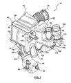
- Figure 1 is a perspective view of the embodiment
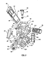
- Figure 2 is an exploded perspective view of the embodiment of Figure 1.
- the air filter assembly includes an air flow chamber portion 12 and a liquid reservoir portion 14.
- the air flow chamber portion 12 defines an air flow inlet 20 and an air flow outlet 22 (Fig. 2).
- An air flow inlet snorkel 24 is attached to the air flow inlet 20.
- the air flow inlet snorkel 24 may include a subsidiary branch inlet 25 for connection to an acoustic resonator- Conveniently, a corrugated air flow outlet duct. illustrated generally as 26, is attached to the air flow outlet 22.
- the air flow outlet duct 26 may be of any suitable configuration and length so that it may be attached to the motor air flow inlet. That inlet may be of any type depending upon the vehicle fuelling system.
- the air flow chamber portion 12 defines a slot 30 for housing a panel filter assembly 32.
- the slot 30 extends downwardly and forwardly toward the air flow outlet thereby providing a generally wedge shaped inlet area on the intake side of the panel filter assembly.
- the panel filter assembly 32 includes a generally U-shaped, injection molded, housing 34 which contains a replaceable filter media 36 and a handle/retainer 38.
- the handle/retainer 38 is received within air flow filter chamber portion clips 40 located on the air flow chamber portion 12 opposite either side of the slot 30.
- the clips 40 and the handle/retainer 38 function to permit replacement of the filter media 36 as part of routine maintenance.
- Air induction systems for automobiles require acoustic considerations in design.
- the air flow chamber portion 12 defines at least one acoustic chamber 50 for attenuation of sound waves in the air induction system.
- a second acoustic chamber 52 which also serves to help in sound attenuation. While the shape and configuration of the acoustic chambers 50 and 52 are open for design and selection by the designer, the requirement for such chambers is one of the significant space issues in designing the assembly of the present invention. Sufficient space must be made available to permit the acoustic design necessary. Acoustic considerations may also require use of a resonator which may be ducted to the snorkel 24. A duct connection 25 may be incorporated into the snorkel 24 for this purpose.
- the panel filter may include a single function filtration media suitable for the purpose of filtering incoming air to the requisite degree of cleanliness.
- the panel filter may include addition media such as hydrocarbon adsorbers which will help diminish any reverse flow of hydrocarbon vapors from the engine fuelling system after engine shut down.
- Such systems work by absorbing the hydrocarbons that might pass upstream from the engine fuelling system and are retained on the adsorber. When the engine is started again, incoming air is drawn through the adsorber and the hydrocarbons are drawn back into the engine for normal combustion.
- the air flow chamber portion 12 and the panel filter housing 34 are injection molded.
- the injection molded parts can then be made with sufficient accuracy to ensure appropriate sealing so that there is no escape of hydrocarbon vapors from the assembly, nor is there any unwanted air inlet leakage.
- the liquid reservoir portion 14 of the assembly 10 comprises an internal closed chamber for retaining of liquids.
- the liquid reservoir portion 14 is advantageously made in a blow molding operation, a manufacturing process which is particularly suited to making hollow articles.
- the liquid reservoir portion 14 comprises an upstanding boss 70 having an inlet aperture 72.
- the air flow chamber portion 12 includes an upstanding boss 74 with an inlet aperture 76. In the assembled condition, the aperture 76 of boss 74 is aligned over aperture 72 of boss 70 to provide a fluid communication conduit to the chamber of liquid reservoir portion 14.
- the liquid handling system advantageously includes a liquid filler pipe 80 having an openable and closable cap 82.
- the liquid filler pipe 80 works together with a seal 84 to sealingly engage the aperture 76 to provide a leak-free fluid communication between the cap 82 and the chamber within the liquid reservoir portion 14.
- the liquid reservoir portion 14 may also include an outstanding and preferably downwardly extending boss 90.
- the outstanding boss 90 may include a pump 92 together with a liquid level sensor 94.
- the pump 92 can deliver fluid from the chamber within the liquid reservoir portion 14 under pressure.
- the liquid reservoir portion 14 can be utilized to contain disposable fluid such as windshield washer fluid. As the chamber is emptied, more fluid can be filled into the container through the cap 82.
- the liquid reservoir portion 14 advantageously includes a recess 35 to receive the lower end of the panel filter assembly 32 when the unit is assembled and the filter panel assembly is put in place.
- the air flow chamber portion 12 may define a retention clip 100.
- the retention clip 100 may then be used to position an additional liquid reservoir 102.
- the additional liquid reservoir 102 may be used for other automobile fluids such as power steering fluid.
- the air flow chamber portion 12 and the liquid reservoir portion 14 are affixed together as an assembly by means of a plurality of screws 110 which may be placed around the periphery of a flange 112 of the air flow chamber portion 12.
- the plurality of screws 110 engage a plurality of bosses 120 formed in the periphery of the liquid reservoir portion 14.
- the assembly 10 may be affixed to the vehicle by means of outstanding flanges such as those illustrated at 130 and 132.
- the flanges 130 and 132 are positioned as necessary so that the assembly may be fixed to the vehicle at convenient mounting points.
- the embodiment illustrated in the figures thus provides an assembly of several components.
- the assembly defines the air flow path for the vehicle from inlet through a filter to a clean air delivery duct and provides appropriate space and configuration to meet the vehicle inlet air flow considerations including acoustic requirements as well as providing an appropriate seal to minimize reverse flow of hydrocarbon vapors on engine shut down.
- the housing defines a slot for use with a panel type filter cartridge which may include suitable media for air cleaning and vapor retention.
- the assembly provides a liquid reservoir with a refill cap and pump mounting.
- the assembly includes an additional reservoir for including an additional liquid such as power steering fluid. This whole assembly can be assembled prior to delivery of the assembly to the typical automobile assembly plant thereby reducing the amount of assembly required at the automotive assembly plant while still providing an assembly meeting a plurality of engine compartment requirements.
Landscapes
- Engineering & Computer Science (AREA)
- Chemical & Material Sciences (AREA)
- Combustion & Propulsion (AREA)
- Mechanical Engineering (AREA)
- General Engineering & Computer Science (AREA)
- Manufacturing & Machinery (AREA)
- Power Steering Mechanism (AREA)
- Filtering Of Dispersed Particles In Gases (AREA)
- Air-Conditioning For Vehicles (AREA)
Applications Claiming Priority (2)
| Application Number | Priority Date | Filing Date | Title |
|---|---|---|---|
| US55995404P | 2004-04-07 | 2004-04-07 | |
| US559954P | 2004-04-07 |
Publications (1)
| Publication Number | Publication Date |
|---|---|
| EP1584811A2 true EP1584811A2 (de) | 2005-10-12 |
Family
ID=34911025
Family Applications (1)
| Application Number | Title | Priority Date | Filing Date |
|---|---|---|---|
| EP05252198A Withdrawn EP1584811A2 (de) | 2004-04-07 | 2005-04-07 | Integriertes Luftansaugsystem |
Country Status (3)
| Country | Link |
|---|---|
| US (1) | US7150260B2 (de) |
| EP (1) | EP1584811A2 (de) |
| CA (1) | CA2503592A1 (de) |
Cited By (3)
| Publication number | Priority date | Publication date | Assignee | Title |
|---|---|---|---|---|
| EP1607616A3 (de) * | 2004-06-14 | 2010-12-15 | MANN+HUMMEL GmbH | Filtergehäuse mit Resonator und Reservoir |
| CN103818236A (zh) * | 2014-03-20 | 2014-05-28 | 重庆长安跨越车辆有限公司 | 一种适用于面包车的发动机进气系统 |
| WO2016082852A1 (en) * | 2014-11-24 | 2016-06-02 | Mann+Hummel Gmbh | Filtering device, filtering element and maintenance process of a filtering device |
Families Citing this family (13)
| Publication number | Priority date | Publication date | Assignee | Title |
|---|---|---|---|---|
| WO2007056589A2 (en) * | 2005-11-09 | 2007-05-18 | Donaldson Company, Inc. | Seal arrangement for filter element; filter element assembly: and, methods |
| US8097055B2 (en) * | 2007-10-29 | 2012-01-17 | Caterpillar Inc. | System for treating exhaust gas |
| US8092563B2 (en) * | 2007-10-29 | 2012-01-10 | Caterpillar Inc. | System for treating exhaust gas |
| US8083822B2 (en) * | 2008-03-06 | 2011-12-27 | Caterpillar Inc. | System for treating exhaust gas |
| US8813708B2 (en) * | 2009-12-10 | 2014-08-26 | Mann+Hummel Gmbh | Air pillow flow guidance and acoustic countermeasure system for an air intake tract |
| USD715417S1 (en) * | 2012-10-31 | 2014-10-14 | Stephen McCoy | Performance enhancing air filtration device |
| US9440175B2 (en) * | 2012-11-01 | 2016-09-13 | Advanced Flow Engineering, Inc. | Interface air filter and assembly |
| USD703803S1 (en) * | 2012-11-29 | 2014-04-29 | K&N Engineering, Inc. | Air filter |
| CN106364313A (zh) * | 2016-11-07 | 2017-02-01 | 中国重汽集团济南动力有限公司 | 一种轻型汽车用空滤器支架总成 |
| US10724483B2 (en) | 2017-08-29 | 2020-07-28 | Ford Global Technologies, Llc | NVH soundtube having integrated hydrocarbon adsorption and air filtration device to control evaporative emissions |
| KR102370942B1 (ko) * | 2017-09-14 | 2022-03-07 | 현대자동차주식회사 | 어댑터 필터고정방식 에어클리너 및 흡기 시스템 |
| CN116670386A (zh) * | 2020-07-14 | 2023-08-29 | 托莱多制模和冲模股份有限公司 | 设有集成宽带调谐器的车辆空气过滤器外壳 |
| CN116099267B (zh) * | 2023-02-20 | 2025-05-27 | 西安交通大学 | 一种水热液化高温高压产物的过滤器 |
Family Cites Families (6)
| Publication number | Priority date | Publication date | Assignee | Title |
|---|---|---|---|---|
| US4440555A (en) | 1982-05-20 | 1984-04-03 | Clark Equipment Company | Engine compartment and air cleaner |
| US4548166A (en) | 1985-01-07 | 1985-10-22 | General Motors Corporation | Engine air cleaner and duct arrangement |
| JP2631391B2 (ja) | 1988-02-26 | 1997-07-16 | 豊田合成株式会社 | フイルター付きタンク |
| US5197426A (en) | 1992-05-05 | 1993-03-30 | Briggs & Stratton Corporation | Integral engine housing |
| US5433772A (en) | 1993-10-15 | 1995-07-18 | Sikora; David | Electrostatic air filter for mobile equipment |
| JP2895407B2 (ja) | 1994-12-01 | 1999-05-24 | 本田技研工業株式会社 | 吸気消音装置 |
-
2005
- 2005-04-05 CA CA002503592A patent/CA2503592A1/en not_active Abandoned
- 2005-04-05 US US11/098,451 patent/US7150260B2/en not_active Expired - Fee Related
- 2005-04-07 EP EP05252198A patent/EP1584811A2/de not_active Withdrawn
Cited By (3)
| Publication number | Priority date | Publication date | Assignee | Title |
|---|---|---|---|---|
| EP1607616A3 (de) * | 2004-06-14 | 2010-12-15 | MANN+HUMMEL GmbH | Filtergehäuse mit Resonator und Reservoir |
| CN103818236A (zh) * | 2014-03-20 | 2014-05-28 | 重庆长安跨越车辆有限公司 | 一种适用于面包车的发动机进气系统 |
| WO2016082852A1 (en) * | 2014-11-24 | 2016-06-02 | Mann+Hummel Gmbh | Filtering device, filtering element and maintenance process of a filtering device |
Also Published As
| Publication number | Publication date |
|---|---|
| US20050224036A1 (en) | 2005-10-13 |
| CA2503592A1 (en) | 2005-10-07 |
| US7150260B2 (en) | 2006-12-19 |
Similar Documents
| Publication | Publication Date | Title |
|---|---|---|
| US7150260B2 (en) | Integrated air induction system | |
| US7610905B2 (en) | Passive evaporative emission control module | |
| US9964078B2 (en) | Air cleaner filter assembly for motor vehicles operating in extreme weather conditions | |
| US5623911A (en) | Fuel vapor treating apparatus | |
| US6390073B1 (en) | Evaporative emission storage canister with integral filter and vent solenoid | |
| KR100986063B1 (ko) | 차량용 캐니스터 | |
| EP0947366A3 (de) | Anordnung eines Luftfilters für ein System zur Rückgewinnung des Kraftstoffdampfes | |
| US5913295A (en) | Combination air cleaner fluid reservoir | |
| JP2002519557A (ja) | ハウジングシステム | |
| EP1043495A2 (de) | Brennstoffzufuhrvorrichtung | |
| FR2861655B1 (fr) | Dispositif d'obturation d'une tubulure de remplissage d'un reservoir a liquide, reservoir equipe d'un tel dispositif et vehicule automobile comprenant un tel reservoir | |
| EP1650426B1 (de) | Nutzfahrzeug | |
| CN100421981C (zh) | 整体式燃料箱和汽化物密封系统 | |
| US7185640B2 (en) | Integrated fuel tank and vapor containment system | |
| CN111535946B (zh) | 用于滤罐的过滤器单元 | |
| JP5021738B2 (ja) | 自動車に用いられる燃料タンク | |
| US7758677B2 (en) | Filtering device | |
| US11613174B2 (en) | Apparatus for purging fuel evaporation gas in fuel system | |
| CN208515377U (zh) | 油箱总成及含有该油箱总成的汽车 | |
| US20240115986A1 (en) | Self-cleaning air filter assembly | |
| US20040003650A1 (en) | Device for determining at least one parameter of a medium flowing through a pipe,comprising a filter for receiving harmful substances in said pipe | |
| JP7749519B2 (ja) | 燃料供給装置 | |
| KR100767519B1 (ko) | 차량용 캐니스터의 통기구조 | |
| WO2025006449A1 (en) | Self-cleaning air filter assembly | |
| KR100276248B1 (ko) | 자동차용 에어크리너 |
Legal Events
| Date | Code | Title | Description |
|---|---|---|---|
| PUAI | Public reference made under article 153(3) epc to a published international application that has entered the european phase |
Free format text: ORIGINAL CODE: 0009012 |
|
| AK | Designated contracting states |
Kind code of ref document: A2 Designated state(s): AT BE BG CH CY CZ DE DK EE ES FI FR GB GR HU IE IS IT LI LT LU MC NL PL PT RO SE SI SK TR |
|
| AX | Request for extension of the european patent |
Extension state: AL BA HR LV MK YU |
|
| STAA | Information on the status of an ep patent application or granted ep patent |
Free format text: STATUS: THE APPLICATION IS DEEMED TO BE WITHDRAWN |
|
| 18D | Application deemed to be withdrawn |
Effective date: 20101103 |