EP1584882A2 - Wasserspeicher, insbesondere Schichtenspeicher - Google Patents
Wasserspeicher, insbesondere Schichtenspeicher Download PDFInfo
- Publication number
- EP1584882A2 EP1584882A2 EP05002066A EP05002066A EP1584882A2 EP 1584882 A2 EP1584882 A2 EP 1584882A2 EP 05002066 A EP05002066 A EP 05002066A EP 05002066 A EP05002066 A EP 05002066A EP 1584882 A2 EP1584882 A2 EP 1584882A2
- Authority
- EP
- European Patent Office
- Prior art keywords
- hot water
- water inlet
- mouth
- cold water
- directed
- Prior art date
- Legal status (The legal status is an assumption and is not a legal conclusion. Google has not performed a legal analysis and makes no representation as to the accuracy of the status listed.)
- Withdrawn
Links
- XLYOFNOQVPJJNP-UHFFFAOYSA-N water Substances O XLYOFNOQVPJJNP-UHFFFAOYSA-N 0.000 title claims abstract description 123
- 229910001220 stainless steel Inorganic materials 0.000 claims description 5
- 239000010935 stainless steel Substances 0.000 claims description 5
- 230000007704 transition Effects 0.000 claims description 2
- 238000009826 distribution Methods 0.000 description 4
- 238000010276 construction Methods 0.000 description 2
- 238000013517 stratification Methods 0.000 description 2
- 238000009827 uniform distribution Methods 0.000 description 2
- 238000004891 communication Methods 0.000 description 1
- 230000001143 conditioned effect Effects 0.000 description 1
- 238000005516 engineering process Methods 0.000 description 1
- 239000012530 fluid Substances 0.000 description 1
- 238000010438 heat treatment Methods 0.000 description 1
- 239000008236 heating water Substances 0.000 description 1
- 238000007654 immersion Methods 0.000 description 1
- 239000008235 industrial water Substances 0.000 description 1
- 230000035484 reaction time Effects 0.000 description 1
- 230000000630 rising effect Effects 0.000 description 1
- 238000003466 welding Methods 0.000 description 1
Images
Classifications
-
- F—MECHANICAL ENGINEERING; LIGHTING; HEATING; WEAPONS; BLASTING
- F28—HEAT EXCHANGE IN GENERAL
- F28D—HEAT-EXCHANGE APPARATUS, NOT PROVIDED FOR IN ANOTHER SUBCLASS, IN WHICH THE HEAT-EXCHANGE MEDIA DO NOT COME INTO DIRECT CONTACT
- F28D20/00—Heat storage plants or apparatus in general; Regenerative heat-exchange apparatus not covered by groups F28D17/00 or F28D19/00
- F28D20/0034—Heat storage plants or apparatus in general; Regenerative heat-exchange apparatus not covered by groups F28D17/00 or F28D19/00 using liquid heat storage material
- F28D20/0039—Heat storage plants or apparatus in general; Regenerative heat-exchange apparatus not covered by groups F28D17/00 or F28D19/00 using liquid heat storage material with stratification of the heat storage material
-
- Y—GENERAL TAGGING OF NEW TECHNOLOGICAL DEVELOPMENTS; GENERAL TAGGING OF CROSS-SECTIONAL TECHNOLOGIES SPANNING OVER SEVERAL SECTIONS OF THE IPC; TECHNICAL SUBJECTS COVERED BY FORMER USPC CROSS-REFERENCE ART COLLECTIONS [XRACs] AND DIGESTS
- Y02—TECHNOLOGIES OR APPLICATIONS FOR MITIGATION OR ADAPTATION AGAINST CLIMATE CHANGE
- Y02E—REDUCTION OF GREENHOUSE GAS [GHG] EMISSIONS, RELATED TO ENERGY GENERATION, TRANSMISSION OR DISTRIBUTION
- Y02E60/00—Enabling technologies; Technologies with a potential or indirect contribution to GHG emissions mitigation
- Y02E60/14—Thermal energy storage
Definitions
- the present invention relates to a hot water tank, in particular Stratified storage tank, with a cold water inlet opening into its lower area, a leading out of the lower area cold water outlet, one in the upper area opening hot water inlet and one from the upper area leading away hot or service water discharge.
- Such a memory is known for example from DE 198 55 482 A1.
- the well-known construction So it is only suitable as a layer memory, if this is a volume of at least 120 liters.
- the present invention has for its object to provide an efficient Stratified storage to create, the storage capacity only about up to 50 liters includes. Accordingly, there is an efficient stratification between hot water and cold water inside the storage tank.
- the gist of the present invention in it, at least the introduced hot water on a short distance in horizontal Direction, i. deflect radially, the deflection should be turbulence-poor.
- This hot water is effectively kept in the upper part of the memory.
- such a flow deflection also takes place in the region of Cold water supply; so that the cold water in the area of the cold water inlet, i.e. is held in the lower area of the memory.
- the associated with the mouth of hot water and / or cold water inlet Strömungsumschiata are preferably plate-shaped, but in particular pot-shaped or cup-shaped.
- the mouth of cold water and / or Hot water inlet is directed into the bowl interior against the shell bottom, the mouth being in each case approximately at the level of the upper edge of the shell-like Strömungsumschiata lies.
- This is a turbulence poor diversion of initiated hot water or cold water introduced in the radial direction causes, in each case on the shortest distance or storage height.
- the goal is one uniform distribution up to a dispensing rate of about 15 liters per minute, according to a performance index of 1.1.
- the reservoir itself is preferably made of stainless steel and has a diameter of about 300 mm.
- the shell-like Strömungsumschieri exist preferably also made of stainless steel and have a diameter of about 80 mm at a shell height of about 20-30 mm. This will be a quick deceleration and achieved good distribution of the introduced hot water and / or cold water.
- the stream of hot water hits centrally on the baffle of the shell-like Strömungsumschelements, wherein these in a diameter range of about 40-60 mm a to the mouth of the hot water inlet directed towards curvature of about 5 mm.
- the hot water pipe, through which hot water in the Memory is introduced has a diameter of about 14-18 mm, in particular about 16 mm, with larger pipe diameters flow advantages bring, but are also expensive to handle. The deformation of pipes with a flow diameter of more than 16 mm is expensive and accordingly expensive.
- the mouth of hot water and cold water inlet is at a preferred Embodiment between the respective associated shell-like Strömungsumschelement on the one hand and a rebounding disk on the other hand, which is still one more uniform distribution of the introduced hot and cold water in radial Direction leads, this embodiment is particularly for larger volumes of water offering.
- the cold water inlet is a flow deflection bowl assigned, which may be as well formed or contoured as the deflection or guide shell assigned to the hot water supply.
- the incoming one cold water preferably occurs in the edge region of the shell, namely especially if it is welded to the cold water connection. This is also possible because of the cold water inlet nozzle in a so-called.
- Handhole cover is welded, which has a special contour, the fast equalization and distribution of the flow favors.
- a fast horizontal Water distribution especially in hot water dispensing operation is possible on a conventional storage temperature sensor directly in the water or in dispensed with a separate immersion sleeve.
- the storage tank temperature sensor can be inexpensively in the embodiment according to the invention as a so-called contact sensor To run.
- the reaction time for the signal to recharge the memory with cold water is fast enough.
- the attachment is only via two welding studs just above or below the round weld between the bottom and cylinder jacket of the Memory. This arrangement allows a comfortable access from the front. Also each one Another way of attaching the contact sensor is conceivable, as long as only one is sufficient direct contact between the storage enclosure and the temperature sensor ensured is.
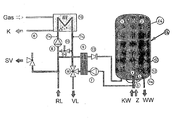
- FIG. 15 shows - a schematic representation of a gas condensing boiler with stratified storage.
- the Stratified storage has the reference numeral 15.
- In the lower area opens Cold water inlet 5.
- a cold water outlet leads from the lower area away, which is in fluid communication with a secondary circuit which a plate heat exchanger 9 with thermal module, a storage loading pump 7 and a check valve 13, wherein the check valve 13 in the plate heat exchanger downstream hot water supply line 1 is arranged. This is to prevent be that hot water from the upper region of the stratified storage 15 in the Secondary circuit pushes back.
- the hot water supply line opens into the upper Area of the stratified storage 15, wherein this hot water inlet with the Reference numeral 1 is characterized. Furthermore leads from the upper area of the Stratified storage tank 15 a hot or service water outlet 2 away. These. Line includes outside of the layer memory 15 a not shown Tap.
- both the mouth of the hot water inlet 1 and the mouth of the cold water inlet 5 is directed in each case to an approximately horizontally extending Strömungsumschelement 16, 17.
- the Strömungsumschetti 16, 17 are pot-shaped or cup-shaped, wherein the edge faces in each case the mouth of hot water and cold water inlet.
- the mouths of cold water and hot water inlet are each approximately at the height of the upper edge of the deflection shells 16, 17th
- the baffle or the bottom of the shell-like Strömungsumschetti 16, 17, to which the mouth of cold water and hot water inlet is directed is curved towards the respective mouth.
- the mouth of the hot water inlet 1 is further directed centrally on the baffle or bottom surface of the associated Strömungsumschelements 16 out.
- the mouth of the cold water inlet can also be arranged centrally, but is preferably directed at the edge on the impact or bottom surface of the associated Strömungsumschelements 17 out.
- the diameter of the memory 15 is approximately 250-350 mm, in particular about 300 mm with a storage volume of up to about 50 liters.
- the shell-like Strömungsumschetti have a middle Diameter of about 80 mm and a rim height of about 20-30 mm.
- the mouth of the hot water inlet is according to the attached drawing directed downwards within the store.
- the mouth of the cold water inlet is directed upwards.
- the flow diameter of the hot water inlet is about 12-18 mm, in particular about 16 mm.
- the flow diameter of the Cold water inlet is about 15-20 mm.
- the Strömungsumschetti 16, 17 exist as well as the memory preferably made of stainless steel. These are pressed or deep-drawn parts.
- a storage temperature sensor is as a contact sensor 12 on the outside of the memory 15, preferably in the transition region between the storage jacket and Storage floor arranged.
- the cold water outlet is in the accompanying drawing with the reference numeral 4th marked with the reference numeral 3, the radial cold water distribution conditioned by the cold water inlet 5 associated Strömungsumschschale 17th is marked.
Landscapes
- Engineering & Computer Science (AREA)
- Physics & Mathematics (AREA)
- Thermal Sciences (AREA)
- Mechanical Engineering (AREA)
- General Engineering & Computer Science (AREA)
- Heat-Pump Type And Storage Water Heaters (AREA)
- Details Of Fluid Heaters (AREA)
Abstract
Description
- 6 =
- Kondensatablauf
- 7 =
- Speicherladepumpe
- 8 =
- x Heizkreispumpe PWM-modulierend
- 9 =
- Plattenwärmetauscher im Thermenmodul
- 10 =
- Heizwasserwärmetauscher
- 11 =
- 3-Wege-Umschaltventil im Thermenmodul
- 13 =
- Rückschlagventil
- 14 =
- integriertes Überströmventil
Des weiteren sei darauf hingewiesen, dass die Prallfläche bzw. der Boden der schalenartigen Strömungsumlenkelemente 16, 17, auf die die Mündung von Kaltwasser- und Warmwasser-Zulauf gerichtet ist, in Richtung zur jeweiligen Mündung hin gewölbt ist. Die Mündung des Warmwasser-Zulaufs 1 ist des weiteren zentral auf die Prall- bzw. Bodenfläche des zugeordneten Strömungsumlenkelements 16 hin gerichtet. Auch die Mündung des Kaltwasser-Zulaufs kann zentral angeordnet sein, ist jedoch vorzugsweise randseitig auf die Prall- bzw. Bodenfläche des zugeordneten Strömungsumlenkelements 17 hin gerichtet.
- RL =
- Rücklauf
- VL =
- Vorlauf
- KW =
- Kaltwasser
- WW =
- Warmwasser
- Z =
- Zirkulationsleitung
- K =
- Kondensat
- 1
- Warmwasserzulauf
- 2
- Warm- bzw. Brauchwasser-Ausleitung
- 3
- Radialströmung des Altwassers
- 4
- Kaltwasserabzug
- 5
- Kaltwasserzulauf
- 15
- Schichtenspeicher
- 16
- Strömungsumlenkschale
- 17
- Strömungsumlenkschale
Claims (13)
- Warmwasserspeicher, insbesondere Schichtenspeicher (15), mit einem in dessen unteren Bereich mündenden Kaltwasserzulauf (5), einem aus dessen unterem Bereich wegführenden Kaltwasserabzug (4), einem in dessen oberen Bereich mündenden Warmwasserzulauf (1) und einer aus dessen oberem Bereich wegführenden Warm- bzw. Brauchwasser-Ausleitung (2),
dadurch gekennzeichnet, dass
die Mündung zumindest des Warmwasserzulaufs (1), insbesondere aber sowohl des Kaltwasserzulaufs (5) als auch des Warmwasserzulaufs (1) jeweils auf sich etwa horizontal erstreckende Strömungsumlenkelemente (16, 17) gerichtet ist. - Warmwasserspeicher nach Anspruch 1,
dadurch gekennzeichnet, dass
die Strömungsumlenkelemente (16, 17) plattenförmig, insbesondere topf- bzw. schalenartig ausgebildet sind. - Warmwasserspeicher nach Anspruch 2,
dadurch gekennzeichnet, dass
bei topf- bzw. schalenartiger Ausbildung der Strömungsumlenkelemente (16, 17) die Mündung von Kaltwasser- und/oder Warmwasser-Zulauf in das Schaleninnere gerichtet ist. - Warmwasserspeicher nach Anspruch 2 oder 3,
dadurch gekennzeichnet, dass
die Mündung von Kaltwasser- und/oder Warmwasser-Zulauf etwa auf Höhe der Oberkante der topf- bzw. schalenartigen Strömungsumlenkelemente (16, 17) liegt. - Warmwasserspeicher nach einem der Ansprüche 1 bis 4,
dadurch gekennzeichnet, dass
die Prall- bzw. Bodenfläche der Strömungsumlenkelemente (16, 17), auf die
die Mündung von Kaltwasser- und/oder Warmwasser-Zulauf gerichtet ist, in Richtung zur besagten Mündung hin gewölbt ist. - Warmwasserspeicher nach einem der Ansprüche 1 bis 5,
dadurch gekennzeichnet, dass
die Mündung des Warmwasserzulaufs (1) zentral auf die Prallfläche des zugeordneten Strömungsumlenkelements (16), die Mündung des Kaltwasserzulaufs (5) dagegen entweder ebenfalls zentral oder randseitig auf die Prallfläche des zugeordneten Strömungsumlenkelements (17) gerichtet ist. - Warmwasserspeicher nach einem der Ansprüche 1-6,
dadurch gekennzeichnet, dass
bei einem Durchmesser desselben in der Größenordnung von etwa 250 mm bis 350 mm, insbesondere etwa 300 mm und einem Speichervolumen von bis zu etwa 50 Liter die schalenartigen Strömungsumlenkelemente einen mittleren Durchmesser von etwa 80 mm und eine Randhöhe von etwa 20-30 mm aufweist. - Warmwasserspeicher nach einem der Ansprüche 5-7,
dadurch gekennzeichnet, dass
bei zur Mündung von Warmwasser- und/oder Kaltwasserzulauf hin gerichteter Wölbung der Prallfläche des Strömungsumlenkelements (16, 17) diese sich über einen mittleren Durchmesser von etwa 40-60 mm erstreckt und eine Höhe von etwa 4-6 mm, insbesondere etwa 5 mm aufweist. - Warmwasserspeicher nach einem der Ansprüche 1-8,
dadurch gekennzeichnet, dass
die Mündung des Warmwasserzulaufs (1) innerhalb des Speichers (15) nach unten gerichtet ist und einen Strömungsdurchmesser von etwa 12-18 mm, insbesondere etwa 15-16 mm aufweist. - Warmwasserspeicher nach einem der Ansprüche 1-9,
dadurch gekennzeichnet, dass
die Strömungsumlenkelemente (16, 17) aus Edelstahl, insbesondere als Preß- oder Tiefziehteil ausgebildet sind. - Warmwasserspeicher nach einem der Ansprüche 1-10,
dadurch gekennzeichnet, dass
ein Speichertemperatur-Fühler als Anlegefühler (12) an der Außenseite des Speichers (15), insbesondere im Übergangsbereich zwischen Speichermantel und Speicherboden angeordnet ist. - Warmwasserspeicher nach einem der Ansprüche 1-11,
dadurch gekennzeichnet, dass
die Mündung des Kaltwasserzulaufs (5) innerhalb des Speichers (15) nach oben gerichtet ist und einen Strömungsdurchmesser von 15-20 mm aufweist. - Warmwasserspeicher nach einem der Ansprüche 1-12,
dadurch gekennzeichnet, dass
die Mündung von Warmwasser- und/oder Kaltwasserzulauf (1 bzw. 5) zwischen dem jeweils zugeordneten schalenartigen Strömungsumlenkelement (16, 17) und einer Rückprallscheibe liegt.
Applications Claiming Priority (2)
| Application Number | Priority Date | Filing Date | Title |
|---|---|---|---|
| DE102004017532 | 2004-04-07 | ||
| DE102004017532A DE102004017532A1 (de) | 2004-04-08 | 2004-04-08 | Wasserspeicher, insbesondere Schichtenspeicher |
Publications (2)
| Publication Number | Publication Date |
|---|---|
| EP1584882A2 true EP1584882A2 (de) | 2005-10-12 |
| EP1584882A3 EP1584882A3 (de) | 2008-05-07 |
Family
ID=34895541
Family Applications (1)
| Application Number | Title | Priority Date | Filing Date |
|---|---|---|---|
| EP05002066A Withdrawn EP1584882A3 (de) | 2004-04-08 | 2005-02-01 | Wasserspeicher, insbesondere Schichtenspeicher |
Country Status (2)
| Country | Link |
|---|---|
| EP (1) | EP1584882A3 (de) |
| DE (1) | DE102004017532A1 (de) |
Families Citing this family (2)
| Publication number | Priority date | Publication date | Assignee | Title |
|---|---|---|---|---|
| DE202009000530U1 (de) | 2009-01-14 | 2009-04-30 | Schulze, Rolf, Dipl.-Ing. | Vorrichtung zum Speichern von unterschiedlichen Wässern in Rotationsschichten |
| DE102012024073A1 (de) | 2012-12-07 | 2013-08-01 | Vaillant Gmbh | Schichtenspeicher |
Citations (5)
| Publication number | Priority date | Publication date | Assignee | Title |
|---|---|---|---|---|
| US4138996A (en) * | 1977-07-28 | 1979-02-13 | Rheem Manufacturing Company | Solar heater freeze protection system |
| AT372179B (de) * | 1980-07-07 | 1983-09-12 | Austria Email Eht Ag | Temperaturregeleinrichtung des wassers in einem wasserspeicherbehaelter |
| US5596952A (en) * | 1995-07-24 | 1997-01-28 | Bradford White Corporation | Indirect water heater |
| DE19855482A1 (de) | 1997-12-02 | 1999-06-10 | Marantec Antrieb Steuerung | Torblatt |
| DE10114505A1 (de) | 2001-03-23 | 2002-09-26 | Bosch Gmbh Robert | Wärmeerzeuger für Heizzwecke und Warmwasserbereitung |
Family Cites Families (15)
| Publication number | Priority date | Publication date | Assignee | Title |
|---|---|---|---|---|
| US2207057A (en) * | 1938-06-01 | 1940-07-09 | Stator Corp | Liquid stratification |
| US2711756A (en) * | 1949-10-26 | 1955-06-28 | Mcgraw Electric Co | Baffle plate for tanks |
| DE2749714A1 (de) * | 1977-11-07 | 1979-05-23 | Walter Dipl Ing Zimmermann | Waermespeicher |
| NL8001008A (nl) * | 1980-02-19 | 1981-09-16 | Eurometaal Nv | Werkwijze voor het regelen van de energiehuishouding van een zonne-energiesysteem, alsmede een daarop gebaseerd zonne-energiesysteem. |
| AT368621B (de) * | 1980-04-10 | 1982-10-25 | Austria Email Eht Ag | Temperaturregeleinrichtung des wassers in einem wasserspeicherbehaelter |
| JPS59173650A (ja) * | 1983-03-23 | 1984-10-01 | Matsushita Electric Ind Co Ltd | 温水ボイラ |
| DE3470943D1 (en) * | 1984-10-15 | 1988-06-09 | Plaatverwerkende Ind Van Wijk | Water heating appliance e.g. a domestic boiler |
| JPS61143692A (ja) * | 1984-12-17 | 1986-07-01 | Keiichi Yasukawa | 温度別蓄熱槽 |
| DD263113A1 (de) * | 1987-07-20 | 1988-12-21 | Schwerin Energiekombinat | Anordnung zur wirbelfreien einleitung von speichermedien in schichtwaermespeicherbehaelter |
| DE4139181A1 (de) * | 1991-11-28 | 1993-06-03 | Euratherm Handels Gmbh | Warmwasserheizungsanlage fuer gebaeude |
| AT409174B (de) * | 1996-09-30 | 2002-06-25 | Vaillant Gmbh | Schichtenspeicher |
| DE29714361U1 (de) * | 1996-08-05 | 1997-12-04 | Joh. Vaillant Gmbh U. Co, 42859 Remscheid | Schichtenspeicher |
| DE19719793A1 (de) * | 1997-05-10 | 1998-11-12 | Christiane Unterste | Modul-Schichtenspeicher-System (MSS-System) |
| GB9800500D0 (en) * | 1998-01-12 | 1998-03-04 | Heatrae Sadia Heating Ltd | Improvements to baffles for water heaters |
| DE10327696A1 (de) * | 2003-06-20 | 2005-01-05 | Robert Bosch Gmbh | Warmwasserspeicher, insbesondere Schichtladespeicher |
-
2004
- 2004-04-08 DE DE102004017532A patent/DE102004017532A1/de not_active Ceased
-
2005
- 2005-02-01 EP EP05002066A patent/EP1584882A3/de not_active Withdrawn
Patent Citations (5)
| Publication number | Priority date | Publication date | Assignee | Title |
|---|---|---|---|---|
| US4138996A (en) * | 1977-07-28 | 1979-02-13 | Rheem Manufacturing Company | Solar heater freeze protection system |
| AT372179B (de) * | 1980-07-07 | 1983-09-12 | Austria Email Eht Ag | Temperaturregeleinrichtung des wassers in einem wasserspeicherbehaelter |
| US5596952A (en) * | 1995-07-24 | 1997-01-28 | Bradford White Corporation | Indirect water heater |
| DE19855482A1 (de) | 1997-12-02 | 1999-06-10 | Marantec Antrieb Steuerung | Torblatt |
| DE10114505A1 (de) | 2001-03-23 | 2002-09-26 | Bosch Gmbh Robert | Wärmeerzeuger für Heizzwecke und Warmwasserbereitung |
Also Published As
| Publication number | Publication date |
|---|---|
| DE102004017532A1 (de) | 2005-11-03 |
| EP1584882A3 (de) | 2008-05-07 |
Similar Documents
| Publication | Publication Date | Title |
|---|---|---|
| EP2397777B1 (de) | Gehäuseeinheit für eine Heizungsanlage | |
| DE102008060088B4 (de) | Ausgleichsbehälter für eine Kühlanlage | |
| EP1936297B1 (de) | Einsatz für einen Warmwasser-Schichtspeicher | |
| EP0683362A1 (de) | Wärmespeicher | |
| DE102011081712A1 (de) | Getränkeauslauf und Getränkespender | |
| DE102011017030A1 (de) | Wärmetauscher mit Kernrohr und Ringkanal | |
| WO2004092321A1 (de) | Vorrichtung und verfahren zur bierbereitung | |
| EP2357424A2 (de) | Speicher zum temperaturgeschichteten Speichern von warmen Flüssigkeiten unterschiedlicher Temperatur | |
| DE102005062660B4 (de) | Warmwasserbereiter sowie Grundbehälter für einen Warmwasserbereiter | |
| DE102004017532A1 (de) | Wasserspeicher, insbesondere Schichtenspeicher | |
| DE102012100423B3 (de) | Schichtenspeicher | |
| AT409175B (de) | Schichtspeicher | |
| EP1489374A1 (de) | Warmwasserspeicher, insbesondere Schichtladespeicher | |
| DE10123305A1 (de) | Schichtspeicher mit einem Speicherbehälter zum Speichern von Wärmeenergie | |
| DE102007041398A1 (de) | Handbrause | |
| DE19756312B4 (de) | Schichtenspeicher | |
| DE4243367A1 (de) | Heiz- und Brauchwasserspeicher | |
| DE102006058160A1 (de) | Warmwasser-Schichtspeicher | |
| DE10304684B4 (de) | Schichtenspeicher | |
| DE10257209B3 (de) | Verteilereinrichtung für eine Warmwasser-Schichtspeichervorrichtung und entsprechende Warmwasser-Schichtspeichervorrichtung | |
| EP0320678A2 (de) | Gerät zur Brauchwasserbereitung und -speicherung | |
| AT408145B (de) | Warmwasserspeicher | |
| DE20300658U1 (de) | Wasserspeicher mit Innenmantel | |
| DE29823188U1 (de) | Heizkessel-Speicher-Kombination | |
| DE29614764U1 (de) | Wasserspeicher |
Legal Events
| Date | Code | Title | Description |
|---|---|---|---|
| PUAI | Public reference made under article 153(3) epc to a published international application that has entered the european phase |
Free format text: ORIGINAL CODE: 0009012 |
|
| AK | Designated contracting states |
Kind code of ref document: A2 Designated state(s): AT BE BG CH CY CZ DE DK EE ES FI FR GB GR HU IE IS IT LI LT LU MC NL PL PT RO SE SI SK TR |
|
| AX | Request for extension of the european patent |
Extension state: AL BA HR LV MK YU |
|
| PUAL | Search report despatched |
Free format text: ORIGINAL CODE: 0009013 |
|
| AK | Designated contracting states |
Kind code of ref document: A3 Designated state(s): AT BE BG CH CY CZ DE DK EE ES FI FR GB GR HU IE IS IT LI LT LU MC NL PL PT RO SE SI SK TR |
|
| AX | Request for extension of the european patent |
Extension state: AL BA HR LV MK YU |
|
| 17P | Request for examination filed |
Effective date: 20080711 |
|
| AKX | Designation fees paid |
Designated state(s): AT BE BG CH CY CZ DE DK EE ES FI FR GB GR HU IE IS IT LI LT LU MC NL PL PT RO SE SI SK TR |
|
| 17Q | First examination report despatched |
Effective date: 20090612 |
|
| STAA | Information on the status of an ep patent application or granted ep patent |
Free format text: STATUS: THE APPLICATION IS DEEMED TO BE WITHDRAWN |
|
| 18D | Application deemed to be withdrawn |
Effective date: 20161011 |