EP1585000A1 - Bilderfassungsvorrichtung für Automatisierungsgeräte - Google Patents
Bilderfassungsvorrichtung für Automatisierungsgeräte Download PDFInfo
- Publication number
- EP1585000A1 EP1585000A1 EP04008517A EP04008517A EP1585000A1 EP 1585000 A1 EP1585000 A1 EP 1585000A1 EP 04008517 A EP04008517 A EP 04008517A EP 04008517 A EP04008517 A EP 04008517A EP 1585000 A1 EP1585000 A1 EP 1585000A1
- Authority
- EP
- European Patent Office
- Prior art keywords
- image
- capture device
- actuator
- image capture
- data
- Prior art date
- Legal status (The legal status is an assumption and is not a legal conclusion. Google has not performed a legal analysis and makes no representation as to the accuracy of the status listed.)
- Granted
Links
Images

Classifications
-
- G—PHYSICS
- G06—COMPUTING OR CALCULATING; COUNTING
- G06T—IMAGE DATA PROCESSING OR GENERATION, IN GENERAL
- G06T1/00—General purpose image data processing
- G06T1/0007—Image acquisition
-
- H—ELECTRICITY
- H04—ELECTRIC COMMUNICATION TECHNIQUE
- H04L—TRANSMISSION OF DIGITAL INFORMATION, e.g. TELEGRAPHIC COMMUNICATION
- H04L12/00—Data switching networks
- H04L12/28—Data switching networks characterised by path configuration, e.g. LAN [Local Area Networks] or WAN [Wide Area Networks]
- H04L12/40—Bus networks
- H04L2012/4026—Bus for use in automation systems
Definitions
- the invention relates to an image capture device for detection of image data one by at least one actuator along a moving path moving object, wherein the image capture device designed as a camera.
- the invention further relates to a control module for such Image capture device.
- Such an image capture device is for example known from DE 100 33 366 A1.
- the image capture device in the form of a camera allows the detection of optical Data of an object generated by a handling device is moved with two actuators.
- the image capture device transmits data to a control computer containing the handling device controls with the two actuators.
- the known handling system can be made of modular, build standardized components. However, it is disadvantageous that several, to be matched components necessary.
- control means For controlling the at least one actuator.
- the image acquisition device fulfills two tasks: Collection and expediently analysis of image data and Furthermore, the control of one or more actuators.
- the actor or the actuators expediently form a component a handling device provided by the image capture device is controlled.
- the Image acquisition device in the form of a camera in addition a controller for one or more actuators, that is for an actuator arrangement.
- In the video area usually 50 or 60 frames per second.
- the image capture device detected in a preferred embodiment as a high-speed camera, preferably 200 to 400 frames per second, including embodiments with greater performance, for example, 1,000 images per second, or lower efficiency with more than about 50-60 frames per second, for example 100 pictures per second, are possible without further ado.
- the image capture device has accordingly via a powerful image processing processor, which additionally fulfills the control tasks.
- the Image acquisition device works expediently in one correlating to the speed of movement of the at least one actuator Speed, especially in real time.
- the Control means are opposite to the image data processing means advantageously prioritized.
- the image capture device advantageously allows a highly dynamic evaluation of image data and generated on this way expediently image analysis data.
- the image analysis data sets the image capture device for the control tasks that is, it controls the actuator (s) based on the image analysis data. It is understood that the invention also includes an image capture device having a provides lower operating speed.
- the control means are advantageously for detection from by the at least one actuator and / or by at least a sensor reported feedback configured in for example, a relative position of an actuator member the actuator or the like is reported.
- the control means are advantageously via a programming interface programmable, with at least one movement of the actuator is programmable.
- the control means work expediently as a flow control.
- For the Programming is a standardized programming language preferred, for example, according to IEC-11631.
- control means as a programmable logic Control (PLC) is appropriate. It is also possible that the Control means a programmable logic controller, so to speak emulate. The control means then work according to one Programmable logic controller, that is, for example the programming of the control means takes the form of a Programmable logic controller.
- PLC programmable logic Control
- the control means communicate with the at least one actuator directly or indirectly.
- the direct communication can be, for example via output interfaces, e.g. a bus interface or the like.
- indirect communication is for example a separate input-output module available as a subordinate unit is executed.
- the image capture device and the input-output module are conveniently via a bus connection connected with each other.
- image capture device contains web interface means to output data in a page description language.
- the image capture device forms expediently a kind of web server, so they by means of an Internet browser is operable.
- the image capture device may Output visualization data and / or programming commands received for programming the control means.
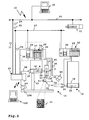
- a handling system 10 shown in Figure 1 includes handling means 11, 12, through an image capture device 13 are controlled.
- a central control computer 30 controls the image capture device 13 and an actuator 31 via a central control bus 29, for example a field bus, an Ethernet bus or the like.
- a central control bus 29 can also be further actuator arrangements, subordinate programmable logic Controllers or the like connected be.
- the image capture device 13 forms a local controller for the handling devices 11, 12, in which a valve battery 14, actuators 16, 17 and a valve battery 15 a Actuator 18 drives.
- a valve battery 14, actuators 16, 17 and a valve battery 15 a Actuator 18 drives To the valve batteries 14, 15 can also connected, not shown in the figure actuators be.
- the valve batteries 14, 15 operate in the present case on a fluidic, in particular pneumatic basis, that is, they act on the actuators 16, 17, 18 with compressed air, to actuate their actuator members 22, 23, 24.
- the image capture device 13 controls the actuators 16 to 18 indirectly via the valve batteries 14, 15, in particular via Control modules 25, 26 of the valve batteries 14, 15, with which the image capture device 13 via a field bus 27, for example an ASi bus (actuator sensor interface) or a CAN bus (Controller Area Network), is connected.
- the Control modules 25, 26 form local input-output modules for Actuation of the actuators 16, 17 and 18.
- the control modules 25, 26 control valve modules, for example valve modules 19, 20, 21, to which the actuators 16, 17, 18 by means of fluid lines, e.g. Compressed air lines are connected.
- the image capture device 13 also for the direct control of actuators, in particular electrical Actors, can be designed, and then no Intermediate input-output modules are necessary.
- the image capture device 13 controls a from her separate illumination device 104, e.g. a lamp, directly on and switches these brightness-dependent on and out.
- bus connection between the image capture device 13 and the control modules 25, 26 can also direct Connections in the form of lines 28 between the image capture device 13 and the control modules 25, 26 are provided be. It is understood that even wireless connections, For example, via a wireless LAN, are possible.
- the image capture device 13 is configured as a camera and has an objective 40. Furthermore, the Image capture device 13 from a separate camera 89 via a line 91 image data 90.
- the handling devices 11, 12 are for handling of Objects provided, for example, workpieces, tools or similar.
- an object 32 that is in the Drawing of the handling device 11 is moved, shown.
- the handling device 11 transfers the object 32 of the handling device 12 and moves the object, for example along a movement path shown schematically 36th
- the handling devices 11, 12 are multi-axis handling devices, which is shown schematically in the drawing are.
- the actuator 16 horizontally oriented arranged on a stand 33.
- the actuator member 22 moves, for example, a piston rod which is arranged on a pneumatic piston, from a housing of the actuator 16 out or in this.
- the Actuator 22 is actuated in the X direction.
- the actuator 16 and the actuator 17 is a pneumatic Linear actuator.
- the actuator 17 is oriented vertically, the means, when actuated by the valve module 20, the actuator member leads 23, for example, a piston rod, a movement in the Y direction, that is, the piston rod 23 moves up or down.
- Aktorglieds 23 is a fluidic holding device in the form of a nipple 34, the corresponding actuation by the valve module 35th the object 32 sucks or repels.
- the valve module 35 is with a vacuum generating device, not shown connected.
- a gripper 37 for example, electric or pneumatic is operable, the object takes 32nd
- the gripper 37 is arranged at the front, free end of the Aktorglieds.
- Actuator 18 is also horizontally oriented, that is Actuator member 24, e.g. a piston rod, is movable in the X direction or drivable.
- pneumatic linear actuators shown. It is understood that other drive variants, For example, electric drives, rotary actuators or the like are possible.
- the image capture device 13 is overlaid by a Control device in the form of the control computer 30 controllable.
- the control computer 30 sends, for example, a control command 39 to the image capture device 13 for movement of the object 32 along the path of movement 36.
- the Execution of the control command 39 acknowledges the image capture device 13, for example, with an acknowledgment 62.
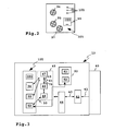
- the image capture device 13 is schematic in FIG shown.
- An image converter 42 converts incident through the object 40 Light 41 in image data 43, here digital image data. It it is understood that analogue image data 43 are also possible.
- a processor 44 performs different based on the image data 43 Control tasks, which will be explained later become.
- the processor 44 is for analyzing image data and additionally designed to carry out control tasks.
- the processor executes program code from program modules 45 for example, an analysis module 46 for analyzing the Image data 43, 90, a control module 47 for controlling the handling devices 11, 12 and a visualization module 48 for the visualization of image data, of control functions or the like.
- the control module 47 controls the actuators 16, 17, 18 on the basis of Control command 39 of the control computer 30 and based on parameter data 52, a movement of the actuators 16, 17, 18 represent. Further, the control module 47 evaluates image analysis data 49, the analysis module 46 based on the image data 43, 90 generated.
- the image analysis data 49 signal for example, a correct or an incorrect movement of the object 32 by the handling devices 11, 12.
- the parameter data 52 includes, for example, an ideal one geometric path 55 of the object 32 along the Trajectory 36, which is shown in Figure 4. Furthermore, can in the parameter data 52 also a time-dependent, ideal Route 65 according to Figure 5 and / or a time-dependent ideal Velocity profile 84 parameterized according to FIG. 6 be.
- the control module 47 forms control means for controlling the actuators 16 to 18.
- the analysis module 46 forms detection means for the detection and in the present case for the analysis of image data, for example the image data 43 and / or 90.
- the control module 47 and the analysis module 46 act in an advantageous manner below described way together:
- the analysis module 46 analyzes the image data 43, 90 in geometric Respect, but also in dynamic terms.
- the analysis module 46 analyzes the image data 43 several positions of the movement path 36, in particular along at least one subsection of the movement path 36.
- the handling devices 11, 12 move the Object 32 along the ideal geometric course 55 according to Figure 4.
- the movements overlap the actuators 16 to 18, so that is a typical geometric History 56 sets.
- the course 56 is located inside a geometric tolerance band 57, which by a bounded lower and upper limit 58, 59 is.
- the analysis module 46 sends a warning information 61st to the control module 47.
- the control module 47 may then, for example send a warning message to the control computer 30 and / or the actuators 16, 17 and / or 18 to a corrected, the ideal geometric path 55 approximate movement of the object 32 to drive.
- the geometric tolerance band 57 is a warning tolerance band, so to speak.
- the analysis module 46 is configured to the object 32 as well optionally further, not shown in the figure Identify objects, including, for example, an identification code or an identification identifier 51 on the object evaluates.
- the identifier 51 is For example, a data matrix code, a bar code or similar.
- the analysis module 46 may e.g. based on Image data 43 also evaluate object features of the object 32, to determine the identity of the object 32.
- the analysis module 46 can display further properties of the object 32 determine, for example, its location, its dimensions, its Distances from one or more obstacles as well as its Surface quality.
- the aforementioned analysis data for example a part number, an identification code, Survey data, distance data, alignment data / location data and / or surface data, the image capture device may 13 to the superimposed control device in Transmit shape of the control computer 30.
- the analysis module 46 is also capable of one or several dynamic properties of the object 32 at least a position along the trajectory 36 to analyze and trigger a follow-up action, for example warning information in the nature of the warning information 36 to send.
- a dynamic property is, for example, by represents the path progression 65 or the velocity course 84.
- the analysis module 46 is parameterized, for example, that the time-dependent path course of the object 32 along the trajectory 36 move within a tolerance band 67 must be that through a lower and an upper limit 68, 69 is limited.
- a typical path-time curve 66 is in Figure 4 shown by a solid line. It is but possible that the path-time history is wrong, which is indicated by a dotted line 70. The dotted Line 70 leaves the tolerance band 67 upwards. Accordingly, the analysis module 46 sends a Warning information in the manner of the warning information 61 to the Control module 47, whereupon this the actuators 16 to 18 to a correct handling of the object 32 is driving.
- tolerance bands for example an alarm tolerance band 79 and an emergency tolerance band 86 for the speed of the object 32 along the trajectory 36 are defined.
- the analysis module 46 sends an alarm message 77 to the control computer 30.
- Such an overrun is for example, by the error-speed course 85 given that reaches an alarm speed 75.
- the analysis module 46 sends an emergency message 78 the control module 47.
- Control module 47 for example, the actuators 16, 17, 18 directly at.
- the control module 47 then sends, for example Hold command 74 to the control modules 25, 26 of the valve batteries 14, 15 about this to a stop of the actuators 16 to 18 to instruct.
- a visualization / parameterization device 102 in the form a personal computer is used to visualize Visualization data 50, which generates the visualization module 48. Furthermore, the device 102 allows a parameterization the parameter data 52 at a parameterization interface 53.
- the image capture device 13 and the visualization / parameterization device 102 communicate via one wireless connection, such as a Wi-Fi connection.
- the parameterization interface 53 contains, for example, a Radio controller.
- the parameterization interface 53 is at Embodiment at the same time a visualization interface to output the visualization data 50, for example an image sequence 93 containing a movement of the object 32 along the trajectory 36 shows.
- the image sequence 93 and the parameter data 52 are in one Memory 92 stored, via a connection, not shown is connected to the processor 44.
- In the store 92 are also not shown in the program modules 45 and may be used by the processor 44 to execute their program code are read from the memory 92.
- the parameterization interface 53 is a kind of web server designed, that is, it provides the visualization data 50, for example, as multimedia data ready, conveniently embedded in code of a page description language, e.g. HTML (Hypertext Markup Language).
- a page description language e.g. HTML (Hypertext Markup Language).
- the memory 92 is for long-term storage of image sequences designed, for example, the image sequence 93. Usually be reflected in the memory 92 image sequences again deleted, for example, the oldest image data be replaced by current image data. In dependence of a trigger condition, such as an alarm condition or an emergency condition (eg, when the emergency tolerance band 86 exits is), the image capture device 13 stores the Image sequence 92 in a long-term memory area of the memory 92. From this long-term storage area, the respective Image sequence for later analysis, for example, with help the visualization device 102, are read.
- a trigger condition such as an alarm condition or an emergency condition (eg, when the emergency tolerance band 86 exits is)
- the image capture device 13 stores the Image sequence 92 in a long-term memory area of the memory 92. From this long-term storage area, the respective Image sequence for later analysis, for example, with help the visualization device 102, are read.
- These Function is particularly in the commissioning of the handling devices 11, 12 advantageous, but also in the ongoing operation,
- FIGS 2 and 3 are interface means 105 of the image capture device 13 partially shown.
- a connection 94 for example, a plug connection
- a plug-in connector is powered by a bus controller 96 serves and serves to connect the field bus 27.
- a Digital-to-analog converter arrangement or analog-to-digital converter arrangement 98 is an input-output connector 97 assigned and allows, for example, the switching and / or dimming the illumination device 104 and / or the Connection of external sensors, for example a position sensor 87 on the actuator 16.
- the position sensor 87 sends a digital or analog position signal 88 to the image capture device 13, the position, for example, the End position, the actuator member 22 signals.
- the control module 47 can the position signal 88 for controlling the actuators 16 to 18, in particular to control the actuator 16, evaluate.
- An Ethernet controller 100 operates an Ethernet port 99, for example in the form of an RJ-45 connector, for connection to the control bus 29. It is understood that others Buses as Ethernet as well as various wired and wireless connection types are possible.
- Display means 101 for example LEDs signal operating states the image capture device 13, for example Normal operation, failure, emergency stop.
- the ports 94, 95, 97 are suitably in a high Degree of protection realized, for example, IP 65/67.
- the image capture device according to the invention can be implemented in software and / or hardware.
- the image capture device 13 may also include a gateway between the field bus 27 and the superimposed control bus 29 form and for example messages of the control modules 25, 26 on the Transform bus 27 into messages on the bus 29 and / or in reverse direction control commands of the control computer 30 the bus 29 as control commands on the bus 27 output.
Landscapes
- Physics & Mathematics (AREA)
- General Physics & Mathematics (AREA)
- Engineering & Computer Science (AREA)
- Theoretical Computer Science (AREA)
- Studio Devices (AREA)
- Image Input (AREA)
- Pharmaceuticals Containing Other Organic And Inorganic Compounds (AREA)
- Silver Salt Photography Or Processing Solution Therefor (AREA)
- Control And Other Processes For Unpacking Of Materials (AREA)
Abstract
Description
- Figur 1
- ein Handhabungssystem, bei dem eine erfindungsgemäße Bilderfassungsvorrichtung zwei Handhabungsvorrichtungen steuert,
- Figur 2
- eine Rückseite der Bilderfassungsvorrichtung gemäß Figur 1,
- Figur 3
- eine schematische Ansicht der Bilderfassungsvorrichtung gemäß Figur 1,
- Figur 4
- schematische geometrische Bewegungsbahnverläufe eines durch die Handhabungsvorrichtungen gemäß Figur 1 bewegten Objekts sowie ein zugeordnetes geometrisches Toleranzband,
- Figur 5
- schematische Weg-Zeit-Verläufe von Bewegungsbahnen, die ein durch die Handhabungsvorrichtungen gemäß Figur 1 bewegtes Objekt durchläuft, sowie ein zugeordnetes geometrisches Toleranzband und
- Figur 6
- schematische zeitabhängige Geschwindigkeitsverläufe eines durch die Handhabungsvorrichtungen gemäß Figur 1 bewegten Objektes sowie zwei zugeordnete Toleranzbänder.
Claims (23)
- Bilderfassungsvorrichtung zur Erfassung von Bilddaten (43, 90) eines durch mindestens einen Aktor (16, 17, 18) entlang einer Bewegungsbahn (36) bewegten Objekts (32), wobei die Bilderfassungsvorrichtung als eine Kamera ausgestaltet ist, dadurch gekennzeichnet, dass sie Steuermittel (47) zur Steuerung des mindestens einen Aktors (16, 17, 18) aufweist.
- Bilderfassungsvorrichtung nach Anspruch 1, dadurch gekennzeichnet, dass die Steuermittel (47) zur Erfassung von durch den mindestens einen Aktor (16, 17, 18) und/oder durch mindestens einen Sensor (87) gemeldete Rückmeldungen ausgestaltet sind.
- Bilderfassungsvorrichtung nach Anspruch 1 oder 2, dadurch gekennzeichnet, dass die Steuermittel (47) über eine Programmier-Schnittstelle programmierbar sind, wobei mindestens ein Bewegungsablauf des mindestens einen Aktors (16, 17, 18) programmierbar ist.
- Bilderfassungsvorrichtung nach einem der vorhergehenden Ansprüche, dadurch gekennzeichnet, dass die Steuermittel (47) mit einer standardisierten Programmiersprache programmierbar sind.
- Bilderfassungsvorrichtung nach einem der vorhergehenden Ansprüche, dadurch gekennzeichnet, dass die Steuermittel (47) als eine Speicherprogrammierbare Steuerung aufgebaut sind und/oder in der Art einer Speicherprogrammierbaren Steuerung funktionieren.
- Bilderfassungsvorrichtung nach einem der vorhergehenden Ansprüche, dadurch gekennzeichnet, dass die Steuermittel (47) zur direkten oder indirekten Kommunikation mit dem mindestens einen Aktor (16, 17, 18) ausgestaltet sind.
- Bilderfassungsvorrichtung nach Anspruch 6, dadurch gekennzeichnet, dass die Steuermittel (47) zu der indirekten Kommunikation mit einem mindestens einem unterlagerten, von der Bilderfassungsvorrichtung separaten Eingabe-/Ausgabemodul (25, 26) zum Empfang von Meldungen bzw. zur Ausgabe von Steuerungsbefehlen an den mindestens einen Aktor (16, 17, 18) kommunizieren.
- Bilderfassungsvorrichtung nach einem der vorhergehenden Ansprüche, dadurch gekennzeichnet, dass sie Web-Schnittstellenmittel zur Eingabe und/oder Ausgabe von Daten in einer Seitenbeschreibungssprache aufweist.
- Bilderfassungsvorrichtung nach Anspruch 8, dadurch gekennzeichnet, dass die Web-Schnittstellenmittel eine Programmier-Schnittstelle zur Programmierung der Steuermittel (47) bilden.
- Bilderfassungsvorrichtung nach einem der vorhergehenden Ansprüche, dadurch gekennzeichnet, dass sie mindestens eine Bus-Schnittstelle (96), insbesondere eine Feldbus-Schnittstelle, zum Anschluss des mindestens einen Aktors (16, 17, 18) oder eines Eingabe-/Ausgabemoduls (25, 26) zur Ansteuerung des Aktors (16, 17, 18) aufweist.
- Bilderfassungsvorrichtung nach Anspruch 10, dadurch gekennzeichnet, dass sie einen Ethernet-Gateway für die mindestens eine Bus-Schnittstelle (96) bildet, wobei die Bilderfassungsvorrichtung an der Bus-Schnittstelle empfangene Meldungen an einer Ethernet-Schnittstelle (100) ausgibt und an der Ethernet-Schnittstelle empfangene Meldungen an der Bus-Schnittstelle ausgibt.
- Bilderfassungsvorrichtung nach einem der vorhergehenden Ansprüche, dadurch gekennzeichnet, dass sie Anschlussmittel (53) für eine Visualisierungsvorrichtung (102) aufweist und/oder Visualisierungsmittel (48) enthält.
- Bilderfassungsvorrichtung nach einem der vorhergehenden Ansprüche, dadurch gekennzeichnet, dass sie von einer überlagerten Steuerungsvorrichtung (30) steuerbar ist.
- Bilderfassungsvorrichtung nach einem der vorhergehenden Ansprüche, dadurch gekennzeichnet, dass sie Erfassungsmittel (42) zum Erfassen von Bilddaten (43, 90) eines insbesondere durch den mindestens einen Aktor (16, 17, 18) bewegten Objekts (32) an mehreren Positionen einer Bewegungsbahn (36) aufweist.
- Bilderfassungsvorrichtung nach einem der vorhergehenden Ansprüche, dadurch gekennzeichnet, dass sie Speichermittel zur Speicherung der Bilddaten (43, 90), insbesondere von Bildsequenzen, aufweist.
- Bilderfassungsvorrichtung nach einem der vorhergehenden Ansprüche, dadurch gekennzeichnet, dass sie Analysemittel (46) zum Ermitteln von Bildanalysedaten (49) des Objektes (32) anhand der Bilddaten (43, 90) aufweist.
- Bilderfassungsvorrichtung nach Anspruch 16, dadurch gekennzeichnet, dass die Bildanalysedaten (49) Qualitätsdaten des bewegten Objekts (32) enthalten.
- Bilderfassungsvorrichtung nach Anspruch 16 oder 17, dadurch gekennzeichnet, dass die Analysemittel (46) zum Erzeugen der Bildanalysedaten (49) anhand einer geometrischen und/oder einer dynamischen Analyse einer Bewegungsbahn (36) des bewegten Objekts (32) ausgestaltet sind.
- Bilderfassungsvorrichtung nach einem der vorhergehenden Ansprüche, dadurch gekennzeichnet, dass die Analysemittel (46) und/oder die Erfassungsmittel und/oder die Steuermittel (47) zumindest teilweise durch einen Prozessor (44) zur Bilddatenverarbeitung gebildet sind.
- Bilderfassungsvorrichtung nach einem der Ansprüche 16 bis 19, dadurch gekennzeichnet, dass die Erfassungsmittel und/oder die Steuermittel (47) zur Erzeugung von Steuerungsdaten anhand der Bildanalysedaten (49) ausgestaltet sind.
- Bilderfassungsvorrichtung nach einem der vorhergehenden Ansprüche, dadurch gekennzeichnet, dass sie durch einen Prozessor (44) ausführbaren Programmcode enthält.
- Steuermodul für eine Bilderfassungsvorrichtung zur Erfassung von Bilddaten (43, 90) eines durch mindestens einen Aktor (16, 17, 18) entlang einer Bewegungsbahn (36) bewegten Objekts (32), wobei die Bilderfassungsvorrichtung als eine Kamera ausgestaltet ist, wobei das Steuerungsmodul Steuermittel (47) zur Steuerung des mindestens einen Aktors (16, 17, 18) aufweist, und wobei das Steuerungsmodul durch einen Prozessor (44) der Bilderfassungsvorrichtung ausführbaren Programmcode enthält.
- Speichermittel mit einem Steuermodul nach Anspruch 22 oder einer Bilderfassungsvorrichtung nach Anspruch 21.
Priority Applications (3)
| Application Number | Priority Date | Filing Date | Title |
|---|---|---|---|
| DE502004008021T DE502004008021D1 (de) | 2004-04-08 | 2004-04-08 | Bilderfassungsvorrichtung für Automatisierungsgeräte |
| EP04008517A EP1585000B1 (de) | 2004-04-08 | 2004-04-08 | Bilderfassungsvorrichtung für Automatisierungsgeräte |
| AT04008517T ATE408178T1 (de) | 2004-04-08 | 2004-04-08 | Bilderfassungsvorrichtung für automatisierungsgeräte |
Applications Claiming Priority (1)
| Application Number | Priority Date | Filing Date | Title |
|---|---|---|---|
| EP04008517A EP1585000B1 (de) | 2004-04-08 | 2004-04-08 | Bilderfassungsvorrichtung für Automatisierungsgeräte |
Publications (2)
| Publication Number | Publication Date |
|---|---|
| EP1585000A1 true EP1585000A1 (de) | 2005-10-12 |
| EP1585000B1 EP1585000B1 (de) | 2008-09-10 |
Family
ID=34896016
Family Applications (1)
| Application Number | Title | Priority Date | Filing Date |
|---|---|---|---|
| EP04008517A Expired - Lifetime EP1585000B1 (de) | 2004-04-08 | 2004-04-08 | Bilderfassungsvorrichtung für Automatisierungsgeräte |
Country Status (3)
| Country | Link |
|---|---|
| EP (1) | EP1585000B1 (de) |
| AT (1) | ATE408178T1 (de) |
| DE (1) | DE502004008021D1 (de) |
Cited By (2)
| Publication number | Priority date | Publication date | Assignee | Title |
|---|---|---|---|---|
| WO2009007312A1 (de) * | 2007-07-06 | 2009-01-15 | Mettler-Toledo Ag | Kontrollgewicht, verfahren und system zur rückverfolgbarkeit solcher gewichte |
| DE102013208355A1 (de) * | 2013-05-07 | 2014-11-13 | Krones Ag | Vorrichtung und Verfahren zur Aufbringung einer Etikettenhülse |
Families Citing this family (2)
| Publication number | Priority date | Publication date | Assignee | Title |
|---|---|---|---|---|
| DE102016107527A1 (de) | 2016-04-22 | 2017-10-26 | Beckhoff Automation Gmbh | Echtzeitumgebung und speicherprogrammierbare Steuerung |
| DE102018133058A1 (de) | 2018-12-20 | 2020-06-25 | Beckhoff Automation Gmbh | Verfahren zum steuern eines automatisierungsprozesses in echtzeit |
Citations (4)
| Publication number | Priority date | Publication date | Assignee | Title |
|---|---|---|---|---|
| DE3031507A1 (de) * | 1980-08-21 | 1982-02-25 | Licentia Patent-Verwaltungs-Gmbh, 6000 Frankfurt | Verfahren zur automatisierung von technischen produktionsablaeufen |
| WO1991017021A1 (en) * | 1990-05-09 | 1991-11-14 | Pietro Torielli | Apparatus for the automatic control of a machine, particularly of a shoe making machine |
| US6061603A (en) * | 1997-09-10 | 2000-05-09 | Schneider Automation Inc. | System for remotely accessing an industrial control system over a commercial communications network |
| US20020186302A1 (en) * | 1999-09-03 | 2002-12-12 | Veijo Pulkinnen | Camera control in a process control system |
-
2004
- 2004-04-08 EP EP04008517A patent/EP1585000B1/de not_active Expired - Lifetime
- 2004-04-08 AT AT04008517T patent/ATE408178T1/de active
- 2004-04-08 DE DE502004008021T patent/DE502004008021D1/de not_active Expired - Lifetime
Patent Citations (4)
| Publication number | Priority date | Publication date | Assignee | Title |
|---|---|---|---|---|
| DE3031507A1 (de) * | 1980-08-21 | 1982-02-25 | Licentia Patent-Verwaltungs-Gmbh, 6000 Frankfurt | Verfahren zur automatisierung von technischen produktionsablaeufen |
| WO1991017021A1 (en) * | 1990-05-09 | 1991-11-14 | Pietro Torielli | Apparatus for the automatic control of a machine, particularly of a shoe making machine |
| US6061603A (en) * | 1997-09-10 | 2000-05-09 | Schneider Automation Inc. | System for remotely accessing an industrial control system over a commercial communications network |
| US20020186302A1 (en) * | 1999-09-03 | 2002-12-12 | Veijo Pulkinnen | Camera control in a process control system |
Cited By (4)
| Publication number | Priority date | Publication date | Assignee | Title |
|---|---|---|---|---|
| WO2009007312A1 (de) * | 2007-07-06 | 2009-01-15 | Mettler-Toledo Ag | Kontrollgewicht, verfahren und system zur rückverfolgbarkeit solcher gewichte |
| EP2165166B1 (de) | 2007-07-06 | 2016-04-06 | Mettler-Toledo GmbH | Kontrollgewicht, verfahren und system zur rückverfolgbarkeit solcher gewichte |
| DE102013208355A1 (de) * | 2013-05-07 | 2014-11-13 | Krones Ag | Vorrichtung und Verfahren zur Aufbringung einer Etikettenhülse |
| EP2801534A3 (de) * | 2013-05-07 | 2014-12-31 | Krones AG | Vorrichtung und Verfahren zur Aufbringung einer Etikettenhülse |
Also Published As
| Publication number | Publication date |
|---|---|
| DE502004008021D1 (de) | 2008-10-23 |
| EP1585000B1 (de) | 2008-09-10 |
| ATE408178T1 (de) | 2008-09-15 |
Similar Documents
| Publication | Publication Date | Title |
|---|---|---|
| EP3140043B1 (de) | Beschichtungsanlage zur beschichtung von bauteilen, insbesondere zur lackierung von kraftfahrzeugkarosseriebauteilen | |
| EP3098034B1 (de) | Auswahl eines gerätes oder eines objektes mit hilfe einer kamera | |
| EP2666727B1 (de) | Hubeinrichtung für eine Verpackungsmaschine | |
| DE102007023585A1 (de) | Einrichtung und Verfahren zum Einmessen von Schwenkaggregaten, insbesondere an Schneidmaschinen | |
| DE10351669B4 (de) | Verfahren und Vorrichtung zum Steuern eines Handhabungsgeräts relativ zu einem Objekt | |
| DE102017213459A1 (de) | Robotersystem | |
| DE112004000504B4 (de) | Aktor mit der Funktion der Steuerung eines Verschiebungsvorgangs | |
| EP1125693A1 (de) | Parallelkinematisches System | |
| DE29709588U1 (de) | Intelligente Steuer- und Regeleinrichtung | |
| EP1975418B1 (de) | Ventilbatterie | |
| DE102008025845A1 (de) | Antriebssystem | |
| DE3710688C2 (de) | Roboterführbares Werkzeug | |
| EP1585000B1 (de) | Bilderfassungsvorrichtung für Automatisierungsgeräte | |
| DE102018109329B4 (de) | Mehrgliedrige aktuierte Kinematik, vorzugsweise Roboter, besonders vorzugsweise Knickarmroboter | |
| DE102020213982B3 (de) | Verfahren zur Inbetriebnahme einer pneumatischen Aktorvorrichtung, Inbetriebnahmesystem und pneumatisches Steuermodul | |
| EP3098033A1 (de) | Ermittlung der roboterachswinkel und auswahl eines roboters mit hilfe einer kamera | |
| EP4263154A1 (de) | Handhabungssystem mit externer steuerbaugruppe | |
| DE102019105466B3 (de) | Verfahren zum Betrieb eines Antriebssystems sowie Antriebssystem | |
| EP1584944B1 (de) | Bilderfassungsvorrichtung und Verfahren zur Erfassung bewegter Objekte | |
| EP1584945B1 (de) | Steuermodul und Ventilbatterie zur Zusammenwirkung mit einer Bilderfassungsvorrichtung | |
| EP2644281B1 (de) | Farbwechsler | |
| DE102021213624A1 (de) | Bearbeitungseinrichtung und Bearbeitungssystem | |
| DE19639212A1 (de) | Sensor-Aktuator-Interfacebaustein | |
| DE3022173A1 (de) | Anordnung und verfaren zur steuerung desarmes eines industrieroboters, insbesondere beim programmieren | |
| DE102015213402A1 (de) | Greifersystem |
Legal Events
| Date | Code | Title | Description |
|---|---|---|---|
| PUAI | Public reference made under article 153(3) epc to a published international application that has entered the european phase |
Free format text: ORIGINAL CODE: 0009012 |
|
| AK | Designated contracting states |
Kind code of ref document: A1 Designated state(s): AT BE BG CH CY CZ DE DK EE ES FI FR GB GR HU IE IT LI LU MC NL PL PT RO SE SI SK TR |
|
| AX | Request for extension of the european patent |
Extension state: AL HR LT LV MK |
|
| 17P | Request for examination filed |
Effective date: 20051025 |
|
| AKX | Designation fees paid |
Designated state(s): AT BE BG CH CY CZ DE DK EE ES FI FR GB GR HU IE IT LI LU MC NL PL PT RO SE SI SK TR |
|
| 17Q | First examination report despatched |
Effective date: 20060922 |
|
| GRAP | Despatch of communication of intention to grant a patent |
Free format text: ORIGINAL CODE: EPIDOSNIGR1 |
|
| RAP1 | Party data changed (applicant data changed or rights of an application transferred) |
Owner name: FESTO AG & CO. KG |
|
| GRAS | Grant fee paid |
Free format text: ORIGINAL CODE: EPIDOSNIGR3 |
|
| GRAA | (expected) grant |
Free format text: ORIGINAL CODE: 0009210 |
|
| AK | Designated contracting states |
Kind code of ref document: B1 Designated state(s): AT BE BG CH CY CZ DE DK EE ES FI FR GB GR HU IE IT LI LU MC NL PL PT RO SE SI SK TR |
|
| REG | Reference to a national code |
Ref country code: GB Ref legal event code: FG4D Free format text: NOT ENGLISH |
|
| REG | Reference to a national code |
Ref country code: CH Ref legal event code: NV Representative=s name: TROESCH SCHEIDEGGER WERNER AG Ref country code: CH Ref legal event code: EP |
|
| REG | Reference to a national code |
Ref country code: IE Ref legal event code: FG4D Free format text: LANGUAGE OF EP DOCUMENT: GERMAN |
|
| REF | Corresponds to: |
Ref document number: 502004008021 Country of ref document: DE Date of ref document: 20081023 Kind code of ref document: P |
|
| REG | Reference to a national code |
Ref country code: SE Ref legal event code: TRGR |
|
| PG25 | Lapsed in a contracting state [announced via postgrant information from national office to epo] |
Ref country code: SI Free format text: LAPSE BECAUSE OF FAILURE TO SUBMIT A TRANSLATION OF THE DESCRIPTION OR TO PAY THE FEE WITHIN THE PRESCRIBED TIME-LIMIT Effective date: 20080910 Ref country code: FI Free format text: LAPSE BECAUSE OF FAILURE TO SUBMIT A TRANSLATION OF THE DESCRIPTION OR TO PAY THE FEE WITHIN THE PRESCRIBED TIME-LIMIT Effective date: 20080910 |
|
| REG | Reference to a national code |
Ref country code: IE Ref legal event code: FD4D |
|
| PG25 | Lapsed in a contracting state [announced via postgrant information from national office to epo] |
Ref country code: IE Free format text: LAPSE BECAUSE OF FAILURE TO SUBMIT A TRANSLATION OF THE DESCRIPTION OR TO PAY THE FEE WITHIN THE PRESCRIBED TIME-LIMIT Effective date: 20080910 Ref country code: BG Free format text: LAPSE BECAUSE OF FAILURE TO SUBMIT A TRANSLATION OF THE DESCRIPTION OR TO PAY THE FEE WITHIN THE PRESCRIBED TIME-LIMIT Effective date: 20081210 Ref country code: ES Free format text: LAPSE BECAUSE OF FAILURE TO SUBMIT A TRANSLATION OF THE DESCRIPTION OR TO PAY THE FEE WITHIN THE PRESCRIBED TIME-LIMIT Effective date: 20081221 |
|
| PG25 | Lapsed in a contracting state [announced via postgrant information from national office to epo] |
Ref country code: PT Free format text: LAPSE BECAUSE OF FAILURE TO SUBMIT A TRANSLATION OF THE DESCRIPTION OR TO PAY THE FEE WITHIN THE PRESCRIBED TIME-LIMIT Effective date: 20090210 Ref country code: CZ Free format text: LAPSE BECAUSE OF FAILURE TO SUBMIT A TRANSLATION OF THE DESCRIPTION OR TO PAY THE FEE WITHIN THE PRESCRIBED TIME-LIMIT Effective date: 20080910 Ref country code: RO Free format text: LAPSE BECAUSE OF FAILURE TO SUBMIT A TRANSLATION OF THE DESCRIPTION OR TO PAY THE FEE WITHIN THE PRESCRIBED TIME-LIMIT Effective date: 20080910 Ref country code: SK Free format text: LAPSE BECAUSE OF FAILURE TO SUBMIT A TRANSLATION OF THE DESCRIPTION OR TO PAY THE FEE WITHIN THE PRESCRIBED TIME-LIMIT Effective date: 20080910 |
|
| PLBE | No opposition filed within time limit |
Free format text: ORIGINAL CODE: 0009261 |
|
| STAA | Information on the status of an ep patent application or granted ep patent |
Free format text: STATUS: NO OPPOSITION FILED WITHIN TIME LIMIT |
|
| PG25 | Lapsed in a contracting state [announced via postgrant information from national office to epo] |
Ref country code: EE Free format text: LAPSE BECAUSE OF FAILURE TO SUBMIT A TRANSLATION OF THE DESCRIPTION OR TO PAY THE FEE WITHIN THE PRESCRIBED TIME-LIMIT Effective date: 20080910 Ref country code: DK Free format text: LAPSE BECAUSE OF FAILURE TO SUBMIT A TRANSLATION OF THE DESCRIPTION OR TO PAY THE FEE WITHIN THE PRESCRIBED TIME-LIMIT Effective date: 20080910 |
|
| 26N | No opposition filed |
Effective date: 20090611 |
|
| BERE | Be: lapsed |
Owner name: FESTO A.G. & CO. KG Effective date: 20090430 |
|
| PG25 | Lapsed in a contracting state [announced via postgrant information from national office to epo] |
Ref country code: MC Free format text: LAPSE BECAUSE OF NON-PAYMENT OF DUE FEES Effective date: 20090430 |
|
| PG25 | Lapsed in a contracting state [announced via postgrant information from national office to epo] |
Ref country code: PL Free format text: LAPSE BECAUSE OF FAILURE TO SUBMIT A TRANSLATION OF THE DESCRIPTION OR TO PAY THE FEE WITHIN THE PRESCRIBED TIME-LIMIT Effective date: 20080910 Ref country code: BE Free format text: LAPSE BECAUSE OF NON-PAYMENT OF DUE FEES Effective date: 20090430 |
|
| PG25 | Lapsed in a contracting state [announced via postgrant information from national office to epo] |
Ref country code: GR Free format text: LAPSE BECAUSE OF FAILURE TO SUBMIT A TRANSLATION OF THE DESCRIPTION OR TO PAY THE FEE WITHIN THE PRESCRIBED TIME-LIMIT Effective date: 20081211 |
|
| PG25 | Lapsed in a contracting state [announced via postgrant information from national office to epo] |
Ref country code: LU Free format text: LAPSE BECAUSE OF NON-PAYMENT OF DUE FEES Effective date: 20090408 |
|
| PG25 | Lapsed in a contracting state [announced via postgrant information from national office to epo] |
Ref country code: HU Free format text: LAPSE BECAUSE OF FAILURE TO SUBMIT A TRANSLATION OF THE DESCRIPTION OR TO PAY THE FEE WITHIN THE PRESCRIBED TIME-LIMIT Effective date: 20090311 |
|
| PG25 | Lapsed in a contracting state [announced via postgrant information from national office to epo] |
Ref country code: TR Free format text: LAPSE BECAUSE OF FAILURE TO SUBMIT A TRANSLATION OF THE DESCRIPTION OR TO PAY THE FEE WITHIN THE PRESCRIBED TIME-LIMIT Effective date: 20080910 |
|
| PG25 | Lapsed in a contracting state [announced via postgrant information from national office to epo] |
Ref country code: CY Free format text: LAPSE BECAUSE OF FAILURE TO SUBMIT A TRANSLATION OF THE DESCRIPTION OR TO PAY THE FEE WITHIN THE PRESCRIBED TIME-LIMIT Effective date: 20080910 |
|
| PGFP | Annual fee paid to national office [announced via postgrant information from national office to epo] |
Ref country code: SE Payment date: 20120416 Year of fee payment: 9 |
|
| PGFP | Annual fee paid to national office [announced via postgrant information from national office to epo] |
Ref country code: NL Payment date: 20130415 Year of fee payment: 10 |
|
| REG | Reference to a national code |
Ref country code: SE Ref legal event code: EUG |
|
| PG25 | Lapsed in a contracting state [announced via postgrant information from national office to epo] |
Ref country code: SE Free format text: LAPSE BECAUSE OF NON-PAYMENT OF DUE FEES Effective date: 20130409 |
|
| PGFP | Annual fee paid to national office [announced via postgrant information from national office to epo] |
Ref country code: CH Payment date: 20140430 Year of fee payment: 11 |
|
| REG | Reference to a national code |
Ref country code: NL Ref legal event code: V1 Effective date: 20141101 |
|
| PG25 | Lapsed in a contracting state [announced via postgrant information from national office to epo] |
Ref country code: NL Free format text: LAPSE BECAUSE OF NON-PAYMENT OF DUE FEES Effective date: 20141101 |
|
| REG | Reference to a national code |
Ref country code: FR Ref legal event code: PLFP Year of fee payment: 12 |
|
| PGFP | Annual fee paid to national office [announced via postgrant information from national office to epo] |
Ref country code: GB Payment date: 20150325 Year of fee payment: 12 |
|
| PGFP | Annual fee paid to national office [announced via postgrant information from national office to epo] |
Ref country code: AT Payment date: 20150407 Year of fee payment: 12 Ref country code: FR Payment date: 20150422 Year of fee payment: 12 Ref country code: IT Payment date: 20150423 Year of fee payment: 12 |
|
| REG | Reference to a national code |
Ref country code: CH Ref legal event code: PL |
|
| PG25 | Lapsed in a contracting state [announced via postgrant information from national office to epo] |
Ref country code: CH Free format text: LAPSE BECAUSE OF NON-PAYMENT OF DUE FEES Effective date: 20150430 Ref country code: LI Free format text: LAPSE BECAUSE OF NON-PAYMENT OF DUE FEES Effective date: 20150430 |
|
| PGFP | Annual fee paid to national office [announced via postgrant information from national office to epo] |
Ref country code: DE Payment date: 20160311 Year of fee payment: 13 |
|
| REG | Reference to a national code |
Ref country code: AT Ref legal event code: MM01 Ref document number: 408178 Country of ref document: AT Kind code of ref document: T Effective date: 20160408 |
|
| GBPC | Gb: european patent ceased through non-payment of renewal fee |
Effective date: 20160408 |
|
| REG | Reference to a national code |
Ref country code: FR Ref legal event code: ST Effective date: 20161230 |
|
| PG25 | Lapsed in a contracting state [announced via postgrant information from national office to epo] |
Ref country code: GB Free format text: LAPSE BECAUSE OF NON-PAYMENT OF DUE FEES Effective date: 20160408 Ref country code: FR Free format text: LAPSE BECAUSE OF NON-PAYMENT OF DUE FEES Effective date: 20160502 |
|
| PG25 | Lapsed in a contracting state [announced via postgrant information from national office to epo] |
Ref country code: AT Free format text: LAPSE BECAUSE OF NON-PAYMENT OF DUE FEES Effective date: 20160408 Ref country code: IT Free format text: LAPSE BECAUSE OF NON-PAYMENT OF DUE FEES Effective date: 20160408 |
|
| REG | Reference to a national code |
Ref country code: DE Ref legal event code: R119 Ref document number: 502004008021 Country of ref document: DE |
|
| PG25 | Lapsed in a contracting state [announced via postgrant information from national office to epo] |
Ref country code: DE Free format text: LAPSE BECAUSE OF NON-PAYMENT OF DUE FEES Effective date: 20171103 |