EP1585041A2 - Méthode de support à la conception de câblage, dispositif de support utilisant cette méthode, et support d'enregistrement lisible par ordinateur - Google Patents
Méthode de support à la conception de câblage, dispositif de support utilisant cette méthode, et support d'enregistrement lisible par ordinateur Download PDFInfo
- Publication number
- EP1585041A2 EP1585041A2 EP05007412A EP05007412A EP1585041A2 EP 1585041 A2 EP1585041 A2 EP 1585041A2 EP 05007412 A EP05007412 A EP 05007412A EP 05007412 A EP05007412 A EP 05007412A EP 1585041 A2 EP1585041 A2 EP 1585041A2
- Authority
- EP
- European Patent Office
- Prior art keywords
- support member
- linear structure
- finite element
- element model
- wire harness
- Prior art date
- Legal status (The legal status is an assumption and is not a legal conclusion. Google has not performed a legal analysis and makes no representation as to the accuracy of the status listed.)
- Ceased
Links
Images





Classifications
-
- G—PHYSICS
- G06—COMPUTING OR CALCULATING; COUNTING
- G06F—ELECTRIC DIGITAL DATA PROCESSING
- G06F30/00—Computer-aided design [CAD]
- G06F30/20—Design optimisation, verification or simulation
- G06F30/23—Design optimisation, verification or simulation using finite element methods [FEM] or finite difference methods [FDM]
-
- G—PHYSICS
- G06—COMPUTING OR CALCULATING; COUNTING
- G06F—ELECTRIC DIGITAL DATA PROCESSING
- G06F2113/00—Details relating to the application field
- G06F2113/16—Cables, cable trees or wire harnesses
Definitions
- the present invention relates to a method of supporting a wiring design of a linear structure, such as a wire harness, a supporting apparatus using the method, and a computer-readable recording medium.
- a vehicle and the like is mounted with a plurality of electric parts, which are connected together by a so-called wire harness as a linear structure in which a plurality of linear members, such as electric wires, communication wires and the like are bundled in a binding member, such as an insulating lock and the like, and an outer armoring member, such as a tape.
- a so-called wire harness as a linear structure in which a plurality of linear members, such as electric wires, communication wires and the like are bundled in a binding member, such as an insulating lock and the like, and an outer armoring member, such as a tape.
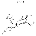
- connectors 2a, 2b, 2c, 2d joined to electric parts and the like are provided at end portions of a wire harness 1.
- various kinds of clips 3a, 3b, 3c, 3d, and a branch point 4 are provided at intermediate portions of the wire harness.
- the design for wiring such a wire harness in a vehicle and the like has been made in many cases by making calculations by using multipurpose analytic software called CAD (Computer Aided Design) and CAE (Computer Aided Engineering), or on the basis of a designer's experience and perception.
- CAD Computer Aided Design
- CAE Computer Aided Engineering
- JP-A-2004-139570 proposes a method of supporting an optimum wiring design by calculating a predictive shape of a linear structure with the physical property of a linear structure, such as a wire harness, i.e. a material thereof and the rigidity thereof with respect to the bend and distortion of each portion thereof taken into consideration, and by displaying the condition of the linear structure of gradual variation of from an initial shape to a predictive shape thereof, by utilizing a finite element process.
- Patent Publication 1 is extremely excellent in that the predictive shape of the linear structure can be precisely calculated considering the physical properties of the linear structure, such as the material or the rigidity against the bending or torsion of each portion. Nevertheless, what has been done on the support member such as the connectors 2a, 2b, 2c and 2d and the clips 3a, 3b, 3c and 3d is to give their center axes only the restriction conditions, as will be described with reference to Fig. 2.
- the predictive shape of the wire harness is calculated by the method of Patent Publication 1. Then, the wire harness takes a shape, as indicated by 1z in Fig. 3. Specifically, the portion of the wire harness, to which a complete restriction type support member 3 is attached, is handled as the complete restriction throughout the entire length of the support member 3. In Fig. 3, letters FX indicate the point of the complete restriction.
- the support member has different rigidities at a portion corresponding to the center axis and at portions corresponding to the two end portions.
- the complete restriction type support member such as a clamp
- the portion corresponding to the center axis CX is subjected to the complete restriction, but the portions corresponding to the two end portions are displaced according to the rigidity.
- the support member is inclined, as indicated at 3', if the point FX is subjected to the complete restriction.
- the wire harness takes the predictive shape depending on the inclination, as indicated by 1z'.
- Patent Publication 1 has failed to consider the physical properties such as the rigidity of the support member. It is, therefore, found that the predictive shape of the wire harness may be different from the actual one, and that the method has room for further improvement.
- the invention has an object to provide a wring design aiding process capable of designing the wiring of a linear structure more practically by calculating the predictive shape of the linear structure while supposing the rigidity or the like of a support member, and an apparatus and a program for the process.
- a method of supporting an optimum wiring design of a linear structure comprising:
- the support member is a complete restriction type support member.
- a complete restriction is applied to a joint corresponding to a center axis of the support member as one of the restriction conditions.
- a complete freedom is applied to a joint corresponding to other than the center axis of the support member as one of the restriction conditions.
- the method further comprising a process of calculating an inclination of the support member with respect to a predetermined reference line on the basis of the joint corresponding to the center axis of the support member and joints corresponding to two end portions of the support member.
- the outputting process outputs the inclination of the support member along with the calculation result.
- a supporting apparatus for supporting an optimum wiring design of a linear structure comprising:
- a computer-readable recording medium for causing a computer to execute the above methods of supporting an optimum wiring design of a linear structure.
- a finite element model is created as a finite element model by making an objective linear structure and a support member of the linear structure as an elastic body, in which a plurality of beam elements having a kept linearity are combined; the predictive shape in the physically balanced state of the finite element model is calculated in accordance with the physical characteristics and the restriction conditions of the linear structure and the support member given to the finite element model; and the calculation result is outputted.
- the predictive shape is calculated supposing even the physical properties of the support member.
- the predictive shape is calculated by using the finite element method while supposing even the physical properties of the support member. It is, therefore, possible to design the wiring of the linear structure more practically.
- a complete restriction is given as a kind of the restriction conditions to a joint corresponding to the center axis of the support member, and a complete freedom is given as a kind of the restriction conditions to a joint corresponding to other than the center axis of the support member. It is, therefore, possible to calculate the predictive shape of the linear structure, more precisely, in case the complete restriction type support member is attached to the intermediate portion.
- an inclination of the support member is determined with respect to a predetermined reference line on the basis of the joint corresponding to the center axis and joints corresponding to two end portions, and is outputted. Therefore, effective information is provided at the time of selecting the support member. Therefore, the information is also effective for the optimum wiring design of the linear structure.
- Fig. 1 is a drawing schematically showing an example of an object wire harness.
- Fig. 2 is a diagram showing the relation between typical support members fixed to the wire harness and the degree of freedom of restrictions.
- Connectors 2a, 2b, 2c, 2d for connecting electric parts are mounted at both end portions of the wire harness 1.
- Various kinds of clips 3a, 3b, 3b, 3c are mounted to intermediate portions of the wire harness 1, which further has a branch point 4. Since the branch lines of the wire harness 1 have basically different number and kind of structural filament members, the thickness, length, elasticity, density and the like thereof are also different.
- the connectors 2a, 2b, 2c, 2d are detachably joined to fixed portions and predetermined portions, which are in accordance with the part fixing direction, of connectors on the side of an electric part, and the end portions of the wire harness are thereby completely restricted.
- the clips 3a, 3b, 3c, 3e completely restrict or rotationally restrict predetermined portions of the wire harness with respect to predetermined portions of a body and a stay of a vehicle.
- the clips basically include an elongated hole clip, and a round hole clip.
- a round hole clip is also called a rotary clip, and has a base seat portion for retaining the wire harness, and a support leg inserted into a round fixing hole provided in a stay and the like.
- the round hole clip can be rotated around a Z-axis (perpendicular direction of a fixing portion).
- the elongated hole clip is also called a fixed clip, and has a base seat portion for retaining the wire harness, and a support leg inserted into an elongated fixing hole provided in a stay and the like.
- This support leg has an elongated hole-like cross-sectional shape substantially identical with the cross-sectional shape of the fixing hole.
- the elongated hole clip is non-rotatable around the Z-axis.
- the elongated hole clips and round hole clips include corrugated elongated hole clips rotatable around an X-axis (longitudinal direction of the wire harness), and corrugated round hole clips.
- the degrees of freedom of restriction in the axial directions and in the directions around the axes of such clips are as shown in Fig. 2.
- the X-axis, Y-axis and Z-axis correspond to three straight lines in a right-hand local coordinate system on joints (or called nodes as well) on the wire harness.
- the Z-axis is set so that the Z-axis is in alignment with the clip axis.
- These setting methods can be changed suitably depending upon the functions in use.
- the drawing also shows for reference the degrees of freedom of restriction of the branch point.
- a joint though it is not shown in the drawing, set arbitrarily on the portion of the wire harness which is other than the above-mentioned restriction point is basically completely free. Such a degree of freedom of restriction is set on each joint for making calculations of predictive paths which will be described later.
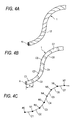
- Fig. 4A is a drawing showing an external view of a wire harness
- Fig. 4B a drawing showing a discrete condition of the wire harness of Fig. 4A
- Fig. 4C a drawing representing the wire harness of Fig. 4A by beam elements and joints.
- Fig. 5 is a drawing for describing the degree of freedom in the wire harness represented by beam elements and joints.
- Fig. 6A is a drawing representing the wire harness by three beam elements
- Fig. 6B a drawing showing the condition of the three beam elements of Fig. 6A combined together.
- hypotheses are built up under use of the finite element method for designing the wire harness.
- the wire harness is also set hypothetically as a uniform cross section, i.e. a homogeneous cross section.
- the cross section is assumed to be circular but it is not always necessary to assume the cross section in this manner. However, in the following statement, a description will be given with the cross section of the wire harness assumed to be circular.
- the wire harness is discretized.
- the wire harness formed by binding a plurality of electric wires 11 by an armoring material, such as a tape 12 as shown in Fig. 4A can be regarded as a continuous body.
- an armoring material such as a tape 12 as shown in Fig. 4A
- a wire harness 1 is divided (discretized) into some beam elements C1, C2, C3,....
- the wire harness is like one rope, so that the wire harness can be regarded as finite pieces of connected beam elements.
- the wire harness can be expressed as a combination of a plurality of beam elements C1, C2, C3,... connected to one another by a plurality of nodes N1, N2, N3,....
- the characteristic values necessary for the beam elements are as follows.
- a density ⁇ and a Poisson's ratio ⁇ , etc. are also used, though they are not directly shown in these characteristic values.
- the parameters concerning the physical properties directly determining an outer shape of a linear structure are called outer shape parameters, and the parameters concerning the physical properties other than the outer shape parameters, such as the second moment of area I, polar moment of area J, longitudinal elastic modulus E and lateral elastic modulus G, density ⁇ , Poisson's ratio ⁇ , etc. shall be called non-outer shape parameters.
- each beam element (C1, C2, C3,...) has two nodes ⁇ and ⁇ .
- the node ⁇ has three translational components and three rotational components, so that the node has a total of six degrees of freedom.
- the beam element C necessarily has twelve degrees of freedom.
- the overall rigidity matrix [K] in a first item of a left side of the balance equation is obtained by converting the rigidity matrix of each element, which is rewritten as the coordinate value is changed momentarily in each incremental step, into a coordinate value in an overall coordinate system, and aggregating the values thus obtained.
- the concrete content of expression of the element rigidity matrix forming a basis is shown in the following equation (2).
- the wire harness shall be expressed by three beam elements C1, C2, C3 for simplicity's sake.
- the quantity of displacement of a node 1 ⁇ of the beam element C1 and that of displacement of a node 2 ⁇ of the beam element C2 become equal, and a force applied to these two nodes is also balanced.
- the quantities of displacement of the node 2 ⁇ of the beam element C2 and node 3 ⁇ of a beam element C3 also become equal, and a force applied to these two nodes is also balanced. Therefore, owing to the continuity of the displacement and the satisfaction of the condition of equilibrium, the beam elements C1 and C2, and the beam elements C2 and C3 can be combined with each other as shown in Fig. 6B.
- the matrixes M1, M2 and M3 on a line 12 and a column 12 in the equation (3) are the same as that shown in the above equation (2).
- the portions M12 and M23 in which the matrixes M1, M2 and M3 overlap each other are portions in which the structural elements of the matrixes are summed up.
- Fig. 7A is a drawing showing the measurement of geometrical moment of inertia and a longitudinal elastic modulus
- Fig. 7B a drawing showing the measurement of a polar moment of area and a lateral elastic modulus.
- the lateral elastic modulus G can be determined by measuring the relation between F and ⁇ .
- each of the lateral elastic modulus G and longitudinal elastic modulus E may also be obtained by a method other than this example of the measuring method.
- the support member is also handled like the wire harness, as described hereinbefore. This is described with reference to Fig. 9 and Fig. 10.
- Fig. 8 is a block diagram showing the construction of the hardware in all of the modes of embodiments of the present invention.
- the apparatus includes a microcomputer 21, an input unit 22, a display 23, a printing unit 24, a storage 25, a communication interface 26 and a read/write unit 27.
- a personal computer is used. Needless to say, a desk top computer and a supercomputer which are other than the personal computer may also be used.
- the microcomputer 21 includes a CPU 21 a (Central Processing Unit), a ROM 21 b for storing a boot program, etc., and a RAM 21 c for temporarily storing the results of various kinds of processing operations.
- CPU 21 a Central Processing Unit
- ROM 21 b read-only memory
- RAM 21 c for temporarily storing the results of various kinds of processing operations.
- the input unit 22 is a keyboard, a mouse and the like for inputting the mentioned various values thereinto
- the display 23 is a LCD, a CRT and the like for displaying the results of processing operations
- the printing unit 24 a printer for printing the results of processing operations.
- the storage 25 stores an installed wiring design support program 29a, i.e. a hard disk drive for storing the results of a process based on this program 29a, while the communication interface 26 is a modem board and the like for making data communication between the communication interface and an external unit by using, for example, internet and a LAN circuit and the like.
- the read/write unit 27 is a device for reading the wiring design support program 29a stored in a recording medium 29, such as a CD and a DVD, and write the calculation results based on this wiring design support program 29a in the recording medium 29. These structural elements are connected together via an inner bus 28.
- the microcomputer 21 installs the wiring design support program 29a read by the read/write unit 27, on the storage 25.
- the microcomputer 21 is started according to the boot program stored in the ROM 21 b, to start the wiring design support program 29a installed.
- the microcomputer 21 performs operations for the shape prediction considering the rigidity or the like of the support member, outputs the processed results from the display unit 23 or the print unit 24, and stores the processed results in the storage 25 or the recording medium 29.
- the wiring design support program 29a can also be installed on another personal computer having the aforementioned basic configuration, and causes, after installed, the computer to function as a wiring design aiding device.
- the wiring design support program 29a may also be serviced not only from the recording medium 29 but also through the communication lines such as the intemet or the LAN.
- Fig. 9 is a flow chart showing the processing procedure of the first embodiment of the invention.
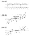
- Fig. 10A to Fig. 10C are diagrams showing the states, in which the wire harness is deformed at the individual processing operations of Fig. 9.
- a clamp is attached as the support member 3 to the intermediate portion of the wire harness.
- the clamp is a complete restriction type support member like the slot clip, as shown in Fig. 2.
- the finite element model 1a corresponding to the wire harness to be designed is created by the aforementioned method, as shown in Fig. 10A.
- the finite element method 1 a is configured of a clamp portion corresponding to the portion to attach the clamp, and a wire harness portion (as will be called the "W/H portion") corresponding to the remaining portion.
- the length of the clamp portion is made to correspond to the longitudinal length of the clamp, for example.
- the clamp portion includes a plurality of beam elements having nodes n3 to n7, and the W/H portion includes a plurality of beam elements having nodes n0 to n2 and n8 to n10.
- the individual joints are assigned at equal intervals.
- the operation of Step S1 corresponds to the finite element mode creating step and the finite element model creating unit.
- the external parameters and the non-external parameters of the clamp portion and the W/H portion are set, respectively, at Step S2 and Step S3.
- the length I, the sectional area A of the clamp portion and the W/H portion are individually set as the external parameters
- the geometrical moment of inertia I, the polar moment of inertia of area J, the Poisson's ratio ⁇ , the density ⁇ , the modulus of longitudinal elasticity E and the modulus of transverse elasticity G of the clamp portion and the W/H portion are individually set as the non-external parameters.
- the individual values are set to raise the rigidity of the clamp portion but to lower the rigidity of the W/H portion.
- the initial restriction conditions are set for the individual joints n0 to n10 of the finite element model 1a.
- the restriction kinds e.g., the complete restriction, the rotational restriction or the complete freedom
- the coordinates and so on, as shown in Fig. 2 are set as the initial restriction conditions.
- the kind of the restriction conditions of the joint n5 corresponding to the clamp center axis is the complete restriction
- the kind of the restriction conditions of the remaining joints n3, n4, n6 and n7 is completely free.
- the clamp center axis extends normal to the face of the Drawing and is designated by a point so that it apparently coincides with the joint n5.
- the kind of the restriction conditions of the joints n0 and n10 corresponding to the stationary point and the control point is the complete restriction, and the kind of the restriction conditions of the remaining joints n1, n2, n8 and n9 is completely free.
- the joint n10 corresponding to the control point is forcibly displaced.
- the individual values set herein relate to the individual elements in the displacement vector ⁇ x ⁇ in the equation (3).
- Step S5 there is calculated the predictive shape or the state, in which the finite element model is physically balanced, according to the aforementioned set values, that is, the initial shape, as shown at 1 a in Fig. 10A.
- the initial restriction conditions are set such that the objective wire harness is so made at its portion between the joints n0 and n10 as to correspond to the straight extended state. Therefore, the initial shape takes the linear shape, as shown as the finite element model 1 a in Fig. 10A. Nevertheless, the initial restriction conditions may also be set to give another shape as the initial shape.
- the wire harnesses When the wire harnesses are shipped from the wire harness maker to a car maker, for example, they are packaged in a container. In case, however, the wire harnesses extracted from the container are to be distributed to the vehicles, their initial shapes vary depending on how they are folded in the container. By reflecting those folded initial shapes as a starting point on the predictive shape, the more practical reaction evaluations can be calculated.
- the finite element method need not always be utilized for the calculations of the initial shape.
- These shape calculating operations are done by the microcomputer 21.
- the input unit 22 is used for setting the individual values, and the display unit 23 and/or the print unit 24 is used for outputting the predictive shape. In the subsequent procedure, too, the shape calculating operations are done by the microcomputer 21.
- the input unit 22 is used for setting the individual values, and the display unit 23 is used for outputting the calculated results.
- Step S6 the joint n10 corresponding to the control point is forcibly displaced to a predetermined position.
- the coordinates of the joint n10 are forcibly displaced.
- the remaining restriction conditions, external parameters and non-external parameters to be adopted take the values set at Step S2, Step S3 and Step S4.
- Step S7 there is calculated the predictive shape or the state, in which the finite element model is physically balanced, according to the aforementioned set values, that is, the predictive shape, as shown at 1z in Fig. 10B.
- the clamp portion between the individual joints n3 and n7 is given a small bent by the physical properties such as the rigidity of the clamp, but that the W/H portion between the joints n0 and n2 and between the joints n8 and n10 is given a large bent by the physical properties of the wire harness.
- the operation of Step S 7 corresponds to the predictive shape calculating step and the predictive shape calculating unit.
- the inclination of the clamp portion is calculated on the basis of the aforementioned predictive shape 1 z.
- This inclination of the clamp portion is calculated by determining the inclination of the clamp portion with respect to a predetermined reference line R, as indicated by ⁇ in Fig. 10C, on the basis of the coordinates of the joint n5 corresponding to the center axis of the clamp and the joints n3 and n7 corresponding to the two end portions.
- a straight line X corresponding to the inclination ⁇ of the clamp portion can be determined by applying the method of least squares to the coordinates of the joint n5 and the joints n3 and n7, for example.
- Step S8 corresponds to the inclination calculating step and the inclination calculating unit.
- Step S9 the results thus calculates are outputted to the display unit 23. It is preferred that the calculation results are outputted to not only the display unit 23 but also the print unit 24 and are recorded in the recording medium 29.
- the output image fleshes out the predictive shape 1 z, as shown in Fig. 10B and Fig. 10C, with the thickness of the wire harness and the shape of the clamp, and further with the inclination ⁇ shown in Fig. 10C. It is also preferred to output the initial shape calculated at Step S4, to the display unit 23.
- the operation of Step S9 corresponds to the result outputting step and the result outputting unit.
- the predictive shape of the wire harness is calculated supposing the rigidity or the like of the support member so that a more practical wiring of the wire harness can be designed.
- the foregoing embodiment exemplifies the case, in which the clamp is attached to the intermediate portion of the wire harness.
- the invention can also be applied to the case (as referred to 2a to 2d of Fig. 1), in which the support member such as the connector is attached to the end portion of the wire harness.
- the support member is attached to the end portion of the wire harness, it is preferred that not the joint corresponding to the center axis of the support member but the joint corresponding to the portion to be fitted on the mating connector is completely constrained.
- the foregoing embodiment exemplifies the case, in which one support member is attached to the wire harness.
- the calculations can also be made on the case of plural support members.
- the support member should not be limited to the clamp but may be any of the kinds enumerated in Fig. 2.
- the foregoing embodiment exemplifies the example of calculating the shape prediction by the forced displacement, but can be applied to the shape prediction at the time when the deformation is made by applying the force to the predetermined joint.
- the invention has been described by way of an example of the wire harness wired as the linear structure in the vehicle. Nevertheless, the invention can naturally be applied not only to such wire harness but also to the hose or tube, which has a simpler structure than that of the wire harness and which is arranged outside of the vehicle, or a general electric wire or a single electric wire.
- the linear structure of the invention includes those hose, tube, general electric wire and single electric wire.
- the invention can also be applied to the wire harness having branches.
- the invention can also be likewise applied to the linear structure having not only the circular section but also a rectangular section, an annular section, an elliptical section and an H-shaped section.
- the linear structure, to which the invention is applied should not be limited to the circular section.
Landscapes
- Engineering & Computer Science (AREA)
- Physics & Mathematics (AREA)
- Theoretical Computer Science (AREA)
- Computer Hardware Design (AREA)
- Evolutionary Computation (AREA)
- Geometry (AREA)
- General Engineering & Computer Science (AREA)
- General Physics & Mathematics (AREA)
- Installation Of Indoor Wiring (AREA)
- Internal Circuitry In Semiconductor Integrated Circuit Devices (AREA)
Applications Claiming Priority (2)
| Application Number | Priority Date | Filing Date | Title |
|---|---|---|---|
| JP2004110992 | 2004-04-05 | ||
| JP2004110992A JP4448367B2 (ja) | 2004-04-05 | 2004-04-05 | 線条構造物の配線設計支援方法、その装置及びそのプログラム |
Publications (2)
| Publication Number | Publication Date |
|---|---|
| EP1585041A2 true EP1585041A2 (fr) | 2005-10-12 |
| EP1585041A3 EP1585041A3 (fr) | 2012-09-19 |
Family
ID=34909468
Family Applications (1)
| Application Number | Title | Priority Date | Filing Date |
|---|---|---|---|
| EP05007412A Ceased EP1585041A3 (fr) | 2004-04-05 | 2005-04-05 | Méthode de support à la conception de câblage, dispositif de support utilisant cette méthode, et support d'enregistrement lisible par ordinateur |
Country Status (3)
| Country | Link |
|---|---|
| US (1) | US7587689B2 (fr) |
| EP (1) | EP1585041A3 (fr) |
| JP (1) | JP4448367B2 (fr) |
Cited By (1)
| Publication number | Priority date | Publication date | Assignee | Title |
|---|---|---|---|---|
| FR2939489A1 (fr) * | 2008-12-08 | 2010-06-11 | Eads Europ Aeronautic Defence | Procede d'optimisation pour routage de tubes sur une structure supportant de petites deformations |
Families Citing this family (8)
| Publication number | Priority date | Publication date | Assignee | Title |
|---|---|---|---|---|
| US7403829B2 (en) * | 2004-12-27 | 2008-07-22 | Kanto Auto Works, Ltd. | Estimating method and apparatus and estimating program of wire harness and recording medium thereof |
| US7823428B1 (en) * | 2006-10-23 | 2010-11-02 | Wright State University | Analytical method for use in optimizing dimensional quality in hot and cold rolling mills |
| WO2008084534A1 (fr) * | 2007-01-10 | 2008-07-17 | Fujitsu Limited | Système, procédé et programme d'aide à la conception |
| US8965738B2 (en) * | 2011-10-05 | 2015-02-24 | Nova Chemicals (International) S.A. | Method of selecting a plastic |
| JP6287392B2 (ja) * | 2013-08-21 | 2018-03-07 | 日立金属株式会社 | ケーブル面外変形予測方法およびケーブル面外変形の予測装置 |
| CN114945923A (zh) * | 2019-11-21 | 2022-08-26 | 日本制铁株式会社 | 连续梁的评价方法、连续梁的评价程序及组合梁的评价方法 |
| JP7348510B2 (ja) * | 2019-11-21 | 2023-09-21 | 日本製鉄株式会社 | 合成梁の評価方法 |
| JP7348509B2 (ja) * | 2019-11-21 | 2023-09-21 | 日本製鉄株式会社 | 連続梁の評価方法及び連続梁の評価プログラム |
Family Cites Families (10)
| Publication number | Priority date | Publication date | Assignee | Title |
|---|---|---|---|---|
| JPH07306883A (ja) * | 1994-05-12 | 1995-11-21 | Fujitsu Ltd | パターン評価支援装置 |
| US6665849B2 (en) * | 1999-06-09 | 2003-12-16 | Interuniversitair Microelektronica Centrum Vzw | Method and apparatus for simulating physical fields |
| JP2002231074A (ja) * | 2001-01-26 | 2002-08-16 | Furukawa Electric Co Ltd:The | ワイヤーハーネスの設計方法およびこの方法をコンピュータに実行させるプログラム |
| EP1236989B1 (fr) * | 2001-03-02 | 2012-09-19 | Sumitomo Wiring Systems, Ltd. | Méthode d'estimation de la durée de flexion, procédé et programme de conception d'un faisceau de câbles |
| KR100514706B1 (ko) * | 2002-09-25 | 2005-09-14 | 야자키 소교 가부시키가이샤 | 배선구조의 배선설계 지원방법, 장치 및 프로그램 |
| JP4600913B2 (ja) | 2002-09-25 | 2010-12-22 | 矢崎総業株式会社 | ワイヤー様構造物の配線設計支援方法、その装置及びそのプログラム |
| JP4600912B2 (ja) * | 2002-09-25 | 2010-12-22 | 矢崎総業株式会社 | ワイヤー様構造物の配線設計支援方法、その装置及びそのプログラム |
| EP1426886B1 (fr) * | 2002-11-19 | 2016-10-19 | Yazaki Corporation | Méthode de prédiction de la forme de structure de cablage, ainsi que l'appareil et le programme |
| JP2005258641A (ja) * | 2004-03-10 | 2005-09-22 | Yazaki Corp | 線条構造物の配線設計支援方法、その装置及びそのプログラム |
| JP4445326B2 (ja) * | 2004-05-21 | 2010-04-07 | 矢崎総業株式会社 | 線条構造物の予測形状計算方法、その装置及びそのプログラム |
-
2004
- 2004-04-05 JP JP2004110992A patent/JP4448367B2/ja not_active Expired - Lifetime
-
2005
- 2005-04-04 US US11/097,273 patent/US7587689B2/en not_active Expired - Lifetime
- 2005-04-05 EP EP05007412A patent/EP1585041A3/fr not_active Ceased
Non-Patent Citations (1)
| Title |
|---|
| None * |
Cited By (2)
| Publication number | Priority date | Publication date | Assignee | Title |
|---|---|---|---|---|
| FR2939489A1 (fr) * | 2008-12-08 | 2010-06-11 | Eads Europ Aeronautic Defence | Procede d'optimisation pour routage de tubes sur une structure supportant de petites deformations |
| WO2010066711A1 (fr) * | 2008-12-08 | 2010-06-17 | European Aeronautic Defence And Space Company Eads France | Procede d'optimisation de la routage de tubes sur une structure supportant de petites deformations |
Also Published As
| Publication number | Publication date |
|---|---|
| EP1585041A3 (fr) | 2012-09-19 |
| JP2005294195A (ja) | 2005-10-20 |
| JP4448367B2 (ja) | 2010-04-07 |
| US7587689B2 (en) | 2009-09-08 |
| US20050222824A1 (en) | 2005-10-06 |
Similar Documents
| Publication | Publication Date | Title |
|---|---|---|
| JP4542791B2 (ja) | ワイヤー様構造物におけるねじれ角計算方法、その装置及びそのプログラム | |
| US7418677B2 (en) | Method of calculating predictive shape of wire structure, calculation apparatus, and computer-readable recording medium | |
| EP1585041A2 (fr) | Méthode de support à la conception de câblage, dispositif de support utilisant cette méthode, et support d'enregistrement lisible par ordinateur | |
| EP1403146A2 (fr) | Procédé pour la conception assistée d'un câblage, appareil et logiciel | |
| EP1403145A1 (fr) | Méthode d'assistance pour la conception de structure de cablage, ainsi que l'appareil et le programme | |
| US7343574B2 (en) | Method of supporting wiring design, supporting apparatus using the method, and computer-readable recording medium | |
| JP4445326B2 (ja) | 線条構造物の予測形状計算方法、その装置及びそのプログラム | |
| EP1426886A2 (fr) | Méthode de prédiction de la forme de structure de cablage, ainsi que l'appareil et le programme | |
| JP4516303B2 (ja) | 線条構造物の配線設計支援方法、その装置及びそのプログラム | |
| JP4235064B2 (ja) | ワイヤー様構造物の配線設計支援方法、その装置及びそのプログラム | |
| JP4452091B2 (ja) | 線条構造物の配線設計支援方法、その装置及びそのプログラム | |
| US7337417B2 (en) | Method of supporting wiring design, supporting apparatus using the method, and computer-readable recording medium | |
| JP4600913B2 (ja) | ワイヤー様構造物の配線設計支援方法、その装置及びそのプログラム | |
| JP4365719B2 (ja) | 線材の予測形状計算方法、その装置及びそのプログラム | |
| JP4344204B2 (ja) | ワイヤー様構造物の形状予測方法、その装置及びそのプログラム | |
| JP3968288B2 (ja) | ワイヤー様構造物の可動範囲予測方法及びその装置 | |
| JP4600911B2 (ja) | ワイヤー様構造物の配線設計支援方法、その装置及びそのプログラム | |
| JP4448368B2 (ja) | 線材の予測形状計算方法、その装置及びそのプログラム | |
| CN100419768C (zh) | 计算线状结构中扭转角的方法以及用于该方法的装置 | |
| JP2007102676A (ja) | ワイヤー様構造物の形状計算方法、そのねじれ計算方法、その形状計算装置、その形状計算システム及びその形状計算プログラム |
Legal Events
| Date | Code | Title | Description |
|---|---|---|---|
| PUAI | Public reference made under article 153(3) epc to a published international application that has entered the european phase |
Free format text: ORIGINAL CODE: 0009012 |
|
| AK | Designated contracting states |
Kind code of ref document: A2 Designated state(s): AT BE BG CH CY CZ DE DK EE ES FI FR GB GR HU IE IS IT LI LT LU MC NL PL PT RO SE SI SK TR |
|
| AX | Request for extension of the european patent |
Extension state: AL BA HR LV MK YU |
|
| RAP1 | Party data changed (applicant data changed or rights of an application transferred) |
Owner name: YAZAKI CORPORATION |
|
| PUAL | Search report despatched |
Free format text: ORIGINAL CODE: 0009013 |
|
| AK | Designated contracting states |
Kind code of ref document: A3 Designated state(s): AT BE BG CH CY CZ DE DK EE ES FI FR GB GR HU IE IS IT LI LT LU MC NL PL PT RO SE SI SK TR |
|
| AX | Request for extension of the european patent |
Extension state: AL BA HR LV MK YU |
|
| RIC1 | Information provided on ipc code assigned before grant |
Ipc: G06F 17/50 20060101AFI20120810BHEP |
|
| 17P | Request for examination filed |
Effective date: 20121212 |
|
| AKX | Designation fees paid |
Designated state(s): DE FR GB IT |
|
| 17Q | First examination report despatched |
Effective date: 20171011 |
|
| STAA | Information on the status of an ep patent application or granted ep patent |
Free format text: STATUS: THE APPLICATION HAS BEEN REFUSED |
|
| 18R | Application refused |
Effective date: 20191022 |