EP1585144A2 - Kabel und Audiokabelanordnung - Google Patents
Kabel und Audiokabelanordnung Download PDFInfo
- Publication number
- EP1585144A2 EP1585144A2 EP05007386A EP05007386A EP1585144A2 EP 1585144 A2 EP1585144 A2 EP 1585144A2 EP 05007386 A EP05007386 A EP 05007386A EP 05007386 A EP05007386 A EP 05007386A EP 1585144 A2 EP1585144 A2 EP 1585144A2
- Authority
- EP
- European Patent Office
- Prior art keywords
- cable
- less
- audio
- insulation
- intermediate layer
- Prior art date
- Legal status (The legal status is an assumption and is not a legal conclusion. Google has not performed a legal analysis and makes no representation as to the accuracy of the status listed.)
- Withdrawn
Links
Images

Classifications
-
- H—ELECTRICITY
- H01—ELECTRIC ELEMENTS
- H01B—CABLES; CONDUCTORS; INSULATORS; SELECTION OF MATERIALS FOR THEIR CONDUCTIVE, INSULATING OR DIELECTRIC PROPERTIES
- H01B11/00—Communication cables or conductors
- H01B11/02—Cables with twisted pairs or quads
- H01B11/12—Arrangements for exhibiting specific transmission characteristics
Definitions
- the present invention relates to a cable, in particular an audio cable, according to the preamble of claim 1 and an audio cable arrangement according to the preamble of claim 8.
- the present invention is based on the object, a cable, in particular specify an audio cable, and an audio cable arrangement that is simple, cost-effective structure, especially for the transmission of audio signals or for connecting speakers are suitable
- an intermediate layer is provided between a conductor and an electrical insulation, which is made of hollow filaments or tubing and / or apertures and / or contains such a proportion of air, that the desired low capacitance, in particular a dielectric constant ⁇ r of the entire cable of less than 2.0 is achievable.
- the intermediate layer is formed as a braid of tubes or Schlaumaterial. This results in a simple and inexpensive construction with significantly improved transmission properties over the prior art.
- An audio cable arrangement according to the invention is characterized in particular by this from that a sheath is provided, in which the cables in two at least one spacer separated groups are performed.
- the cladding is elastic and reticulated in which as pipes or hoses trained spacers are used. This leads to a simple construction with very good transmission properties.
- Another The advantage is that a modular design is made possible, ie individual Cable and spacers used as needed and by the preferred elastic sheath are held together. So becomes a universal Usability and adaptability to the particular circumstances allows.
- the cable 1 shown in Fig. 1 is in particular a Audio cable, preferably for connection not shown speakers or dg1.
- the cable 1 can basically also be used for other purposes become.
- the cable 1 has a conductor 2, which is preferably designed as a stranded wire is and consists at least essentially of copper
- the cable 1 further has an associated insulation 3, in particular is made of a suitable plastic and preferably by extrusion is made.
- the intermediate layer 4 has Openings 5 and is made of hollow filaments or tubing. 6 produced.
- the intermediate layer 4 is formed as a braid.
- the intermediate layer 4 serves a certain distance from particular Ensure at least 1 to 3 mm between the conductor 2 and the insulation 3. In this case, the intermediate layer 4 supports the insulation 3 at least in substantially uniformly and extends along the insulation 3,
- the openings 5 are preferably diamond-shaped in the illustrated example formed and in particular have a size in the range of 1 to 5 mm, preferably 2 to 4 mm.
- the optical coverage of the conductor 2 through the intermediate layer 4 is at Representation example less than 50%, preferably less than 40%, in particular less than 30%, and more preferably is substantially 25% or less.
- the intermediate layer 4 is preferably made of a material with a dielectric constant ⁇ r smaller than 2.5 and is preferably made of plastic, in particular Pernuoralkoxy polymer (PFA) or polyethylene.
- PFA Pernuoralkoxy polymer
- Hose material 6 is particularly thin-walled, hollow and / or flexible. In the illustrated example, it has a diameter of 0.5 to 3 mm, preferably less than 2 mm, in particular less than 1.5 mm and very particularly preferably of substantially 1.1 mm or less
- the insulation 3 is directly extruded on the intermediate layer 4 or in otherwise suitably applied. It is preferably continuous, especially coat-like, formed and consists of a suitable Plastic.
- the cable 1 is not shielded.
- a shield not shown, may be provided, possibly with a second intermediate layer between the insulation 3 and then externally applied, not shown shield.
- the proposed cable 1 is due to the flexible intermediate layer 4th overall very flexible and therefore easy to lay and easy to handle.
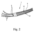
- Fig. 2 shows a schematic representation of a proposed audio cable arrangement 7, the multiple cables 1 in a common enclosure. 8 having.
- the envelope 8 is formed like a net in the representation example. she can However, for example, also hose-like or in any other suitable manner be educated.
- the envelope 8 is preferably flexible and / or elastic. She For example, Teflon or other suitable material.
- the audio cable assembly 7 further comprises at least one, preferably also in the enclosure 8 arranged spacers 9 to the cables 1 in at least two separate groups 10 to lead.
- spacers 9 to the cables 1 in at least two separate groups 10 to lead.
- the spacer 9 is preferably tubular or tubular, in particular thin-walled, hollow and / or flexible. In the illustrated embodiment, it consists of a material with a dielectric constant ⁇ r less than 2.5, in particular of plastic, such as perfluoroalkoxy polymer or polyethylene.
- the spacer 9 extends along the cable 1 in the enclosure 8 and ensures that the two groups 10 of the cables 1 remain disconnected. Especially for this purpose, a plurality of spacers 9 are received by the enclosure 8.
- the envelope 8 holds the cable 1 and spacers 9 preferably non-positively due to their inherent elasticity together. This will be a simple one Mounting the audio cable assembly 7 allows.
- the serving can 8 as needed also consistently or, closed, possibly even as Heat shrink tubing or the like., Be formed.
- the enclosure 8 allows a particularly simple installation and adjustment to the respective circumstances.
- a modular construction of the audio cable assembly 7 with the appropriate number of cables 1 and spacers 9 allows, in addition, also different sizes - In particular in terms of length and diameter - of wrappings. 8 can be used.
- the cables 1 are preferably each clearly identified to confusion when connecting to avoid.
- the cable 1 according to the illustration example has an overall dielectric constant ⁇ r less than 2.0, preferably less than 1.8 and in particular less than 1.6. The same applies to the cables 1 in the audio cable arrangement 7.
- the enclosure 8 of the flat cable assembly or audio cable assembly 7 is preferably woven to achieve the desired inherent elasticity in the transverse direction Longitudinal extension of the cable 1 and 9 spacers to achieve.
- the individual threads or the like run at least substantially vertically and parallel to said longitudinal extent.
- Fig. 2 are the threads or the like. Shown only obliquely for purposes of illustration.
- the spacers 9 only to simplify the Representation about unspecified end sections or terminators 8 serving.
- the spacers 9 end within the enclosure 8 or in the end pieces, in particular such can be closed, that the spacers 9 do not slip out unintentionally can.
Landscapes
- Communication Cables (AREA)
- Insulated Conductors (AREA)
Abstract
Description
- Fig. 1
- eine schematische Ansicht eines vorschlagsgemäßen Kabels; und
- Fig. 2
- eine schematische Ansicht einer vorschlagsgemäl3en Audiokabelanordnung.
Claims (12)
- Kabel (1), insbesondere Audiokabel, vorzugsweise nicht abgeschirmt, mit einem Leiter (2) und einer elektrischen Isolierung (3),
dadurch gekennzeichnet, daß das Kabel (1) eine Dielektrizitätskonstante εr kleiner 2,0 und/oder zwischen dem Leiter (2) und der Isolierung (3) eine Zwischenschicht (4) aufweist, die mit Durchbrechungen (5) versehen und/oder aus Hohlfilamenten oder Schlauchmaterial (6) hergestellt ist - Kabel nach Anspruch 1, dadurch gekennzeichnet, daß der Leiter (2) als Litze ausgebildet ist und/oder zumindest im wesentlichen aus Kupfer besteht und/oder daß die Dielektrizitätskonstante εr kleiner 1,8, insbesondere kleiner 1,6 ist.
- Kabel nach Anspruch 1 oder 2, dadurch gekennzeichnet, daß die optische Überdeckung des Leiters (2) durch die Zwischenschicht (4) kleiner 50 %, vorzugsweise kleiner 40 %, insbesondere kleiner 30 %, ist und besonders bevorzugt im wesentlichen 25 % oder weniger beträgt
- Kabel nach einem der voranstehenden Ansprüche, dadurch gekennzeichnet, daß die Zwischenschicht (4) als Geflecht, Gewebe, Gelege oder Einzelwendel ausgebildet ist, und/oder daß die Durchbrechungen (5) rautenförmig ausgebildet sind.
- Kabel nach einem der voranstehenden Ansprüche, dadurch gekennzeichnet, daß das Schlauchmaterial (6) aus einem Material mit einer Dielektrizitätskonstanten εr kleiner 2,5 und/oder aus Kunststoff, insbesondere Perfluoralkoxy-Polymer oder Polyethylen, besteht
- Kabel nach einem der voranstehenden Ansprüche, dadurch gekennzeichnet, daß das Schlauchmaterial (6) dünnwandig, hohl und/oder flexibel ausgebildet ist und/oder daß das Schlauchmaterial (6) einen Durchmesser von 0,5 bis 3 mm, vorzugsweise kleiner 2 mm, insbesondere kleiner 1,5 mm, und ganz bevorzugt von im wesentlichen 1,1 mm oder weniger aufweist.
- Kabel nach einem der voranstehenden Ansprüche, dadurch gekennzeichnet, daß die Isolierung (3) auf die Zwischenschicht (4) extrudiert ist und/oder daß die Isolierung (3) durchgehend, insbesondere mantelartig, ausgebildet ist und/oder daß die Isolierung (3) aus Kunststoff besteht.
- Audiokabelanordnung (7) mit mehreren elektrisch isolierten Kabeln (1),
dadurch gekennzeichnet, daß die Kabel (1) gemäß einem der voranstehenden Ansprüche ausgebildet sind und die Audiokabelanordnung (7) eine Umhüllung (8) aufweist, in der die Kabel (1) in zwei durch mindestens einen Abstandhalter (9) getrennten Gruppen (10) geführt sind. - Audiokabelanordnung nach Anspruch 8, dadurch gekennzeichnet, daß die Audiokabelanordnung (7) modular aufgebaut ist und/oder einen zumindest im wesentlichen flachen, insbesondere rechteckigen, Querschnitt aufweist.
- Audiokabelanordnung nach Anspruch 8 oder 9, dadurch gekennzeichnet, daß die Umhüllung (8) zumindest bereichsweise, insbesondere auf gegenüberliegenden Flachseiten oder im Bereich der Abstandhalter (9), netzartig und/oder elastisch ausgebildet ist, und/oder daß die Umhüllung (8) aus Kunststoff, insbesondere Teflon und/oder zumindest abschnittsweise aus gewebtem Material besteht.
- Audiokabelanordnung nach einem der Ansprüche 8 bis 10, dadurch gekennzeichnet, daß der Abstandhalter (9) schlauchförmig oder rohrförmig, insbesondere dünnwandig, hohl und/oder flexibel, ausgebildet ist und/oder daß sich der Abstandhalter (9) entlang der Kabel (1) in der Umhüllung (8) und/oder zwischen den zwei Gruppen (10) der Kabel (1) erstreckt
- Audiokabelanordnung nach einem der Ansprüche 8 bis 11, dadurch gekennzeichnet, daß der Abstandhalter (9) aus einem Material mit einer Dielektrizitätskonstanten εr kleiner 2,5 und/oder aus Kunststoff, insbesondere Perfluoralkoxy-Polymer oder Polyethylen, besteht.
Applications Claiming Priority (4)
| Application Number | Priority Date | Filing Date | Title |
|---|---|---|---|
| DE202004005805 | 2004-04-08 | ||
| DE202004005805U | 2004-04-08 | ||
| DE202004011967U DE202004011967U1 (de) | 2004-04-08 | 2004-07-30 | Kabel und Audiokabelanordnung |
| DE202004011967U | 2004-07-30 |
Publications (2)
| Publication Number | Publication Date |
|---|---|
| EP1585144A2 true EP1585144A2 (de) | 2005-10-12 |
| EP1585144A3 EP1585144A3 (de) | 2006-02-08 |
Family
ID=34913383
Family Applications (1)
| Application Number | Title | Priority Date | Filing Date |
|---|---|---|---|
| EP05007386A Withdrawn EP1585144A3 (de) | 2004-04-08 | 2005-04-05 | Kabel und Audiokabelanordnung |
Country Status (1)
| Country | Link |
|---|---|
| EP (1) | EP1585144A3 (de) |
Family Cites Families (3)
| Publication number | Priority date | Publication date | Assignee | Title |
|---|---|---|---|---|
| US2585484A (en) * | 1947-06-25 | 1952-02-12 | Fairchild Camera Instr Co | Method of making high-frequency transmission line |
| US4440973A (en) * | 1980-06-05 | 1984-04-03 | Champlain Cable Corporation | Coaxial cables |
| US20040055777A1 (en) * | 2002-09-24 | 2004-03-25 | David Wiekhorst | Communication wire |
-
2005
- 2005-04-05 EP EP05007386A patent/EP1585144A3/de not_active Withdrawn
Also Published As
| Publication number | Publication date |
|---|---|
| EP1585144A3 (de) | 2006-02-08 |
Similar Documents
| Publication | Publication Date | Title |
|---|---|---|
| DE69906052T2 (de) | Abgeschirmtes kabel und sein herstellungsverfahren | |
| DE69111750T2 (de) | Elektrisches Kabel mit hoher Übertragungsgeschwindigkeit. | |
| DE3779828T2 (de) | Schraubenfoermig gewickelter flexibler schlauch. | |
| EP0619583B1 (de) | Elektrisches Rundkabel | |
| DE4214380A1 (de) | Uebertragungsleitung mit fluiddurchlaessigem mantel | |
| DE19706753A1 (de) | Kabel mit voneinander beabstandeten Wendeln | |
| EP3103122B1 (de) | Datenkabel | |
| DE69408613T2 (de) | Hochfrequenzübertragungskabel | |
| EP3132513B1 (de) | Kabelanordnung | |
| DE10303809A1 (de) | Datenübertragungskabel zum Anschluss an orstveränderliche Geräte | |
| DE2644252A1 (de) | Flachbandleitung mit folienfoermigen durchbrochenen metallischen einlagen | |
| DE10315609B4 (de) | Datenübertragungskabel | |
| EP3147913B1 (de) | Konfektionierbares datenübertragungskabel | |
| DE3043778C2 (de) | HF-Koaxialkabel | |
| DE10119653C1 (de) | Mehrleiteranordnung zur Energie- und/oder Datenübertragung | |
| EP1451497B1 (de) | Kunststoffschlauch, insbesondere pneumatikschlauch | |
| WO2005069314A1 (de) | Koaxialkabel | |
| DE212021000163U1 (de) | Kabel | |
| EP2989641B1 (de) | Hochgeschwindigkeitsdatenkabel | |
| EP1585144A2 (de) | Kabel und Audiokabelanordnung | |
| DE60032587T2 (de) | Strahlendes kabel | |
| DE102014013558B4 (de) | Audiokabel zur Signalübertragung | |
| DE202004011967U1 (de) | Kabel und Audiokabelanordnung | |
| EP0304007A1 (de) | Einrichtung zur elektrischen Beheizung von Rohren, Behältern und dergleichen | |
| EP1134749B1 (de) | Elektrische Leitung |
Legal Events
| Date | Code | Title | Description |
|---|---|---|---|
| PUAI | Public reference made under article 153(3) epc to a published international application that has entered the european phase |
Free format text: ORIGINAL CODE: 0009012 |
|
| AK | Designated contracting states |
Kind code of ref document: A2 Designated state(s): AT BE BG CH CY CZ DE DK EE ES FI FR GB GR HU IE IS IT LI LT LU MC NL PL PT RO SE SI SK TR |
|
| AX | Request for extension of the european patent |
Extension state: AL BA HR LV MK YU |
|
| PUAL | Search report despatched |
Free format text: ORIGINAL CODE: 0009013 |
|
| AK | Designated contracting states |
Kind code of ref document: A3 Designated state(s): AT BE BG CH CY CZ DE DK EE ES FI FR GB GR HU IE IS IT LI LT LU MC NL PL PT RO SE SI SK TR |
|
| AX | Request for extension of the european patent |
Extension state: AL BA HR LV MK YU |
|
| 17P | Request for examination filed |
Effective date: 20060808 |
|
| AKX | Designation fees paid |
Designated state(s): AT BE BG CH CY CZ DE DK EE ES FI FR GB GR HU IE IS IT LI LT LU MC NL PL PT RO SE SI SK TR |
|
| STAA | Information on the status of an ep patent application or granted ep patent |
Free format text: STATUS: THE APPLICATION IS DEEMED TO BE WITHDRAWN |
|
| 18D | Application deemed to be withdrawn |
Effective date: 20091103 |