EP1585211A1 - Générateur d'énergie électrique utilisé dans une roue de véhicule - Google Patents
Générateur d'énergie électrique utilisé dans une roue de véhicule Download PDFInfo
- Publication number
- EP1585211A1 EP1585211A1 EP04008383A EP04008383A EP1585211A1 EP 1585211 A1 EP1585211 A1 EP 1585211A1 EP 04008383 A EP04008383 A EP 04008383A EP 04008383 A EP04008383 A EP 04008383A EP 1585211 A1 EP1585211 A1 EP 1585211A1
- Authority
- EP
- European Patent Office
- Prior art keywords
- receiving space
- electric generator
- vehicle wheel
- base wall
- stator coil
- Prior art date
- Legal status (The legal status is an assumption and is not a legal conclusion. Google has not performed a legal analysis and makes no representation as to the accuracy of the status listed.)
- Withdrawn
Links
- 230000001105 regulatory effect Effects 0.000 claims description 9
- 238000004873 anchoring Methods 0.000 claims description 4
- 239000002184 metal Substances 0.000 description 9
- 230000002411 adverse Effects 0.000 description 2
- 230000004048 modification Effects 0.000 description 2
- 238000012986 modification Methods 0.000 description 2
- 239000004020 conductor Substances 0.000 description 1
- 238000010586 diagram Methods 0.000 description 1
- 230000000694 effects Effects 0.000 description 1
- 230000002688 persistence Effects 0.000 description 1
Images


Classifications
-
- H—ELECTRICITY
- H02—GENERATION; CONVERSION OR DISTRIBUTION OF ELECTRIC POWER
- H02K—DYNAMO-ELECTRIC MACHINES
- H02K7/00—Arrangements for handling mechanical energy structurally associated with dynamo-electric machines, e.g. structural association with mechanical driving motors or auxiliary dynamo-electric machines
- H02K7/18—Structural association of electric generators with mechanical driving motors, e.g. with turbines
- H02K7/1807—Rotary generators
- H02K7/1846—Rotary generators structurally associated with wheels or associated parts
-
- B—PERFORMING OPERATIONS; TRANSPORTING
- B60—VEHICLES IN GENERAL
- B60Q—ARRANGEMENT OF SIGNALLING OR LIGHTING DEVICES, THE MOUNTING OR SUPPORTING THEREOF OR CIRCUITS THEREFOR, FOR VEHICLES IN GENERAL
- B60Q1/00—Arrangement of optical signalling or lighting devices, the mounting or supporting thereof or circuits therefor
- B60Q1/26—Arrangement of optical signalling or lighting devices, the mounting or supporting thereof or circuits therefor the devices being primarily intended to indicate the vehicle, or parts thereof, or to give signals, to other traffic
- B60Q1/32—Arrangement of optical signalling or lighting devices, the mounting or supporting thereof or circuits therefor the devices being primarily intended to indicate the vehicle, or parts thereof, or to give signals, to other traffic for indicating vehicle sides, e.g. clearance lights
- B60Q1/326—Arrangement of optical signalling or lighting devices, the mounting or supporting thereof or circuits therefor the devices being primarily intended to indicate the vehicle, or parts thereof, or to give signals, to other traffic for indicating vehicle sides, e.g. clearance lights on or for wheels
Definitions
- the invention relates to an electric generator, more particularly to an electric generator for use with a vehicle wheel.
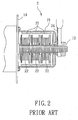
- Figure 1 illustrates a conventional electric generator 2 for use with a bicycle 1.
- the conventional electric generator 2 is mounted on a wheel axle 12 and provides electric power to a lamp 13 mounted on the bicycle 1.
- the conventional electric generator 2 is shown to include a housing 21, three stator coils 22, and three magnet rings 23.
- the housing 21 is secured to a wheel hub 14 on the wheel axle 12 such that the housing 21 is capable of rotating about the wheel axle 12 when a bicycle wheel 11 (see Figure 1) rotates.
- the stator coils 22, which are connected in series, are disposed in the housing 21 and are mounted on the wheel axle 12.
- the magnet rings 23 are disposed in the housing 21 around the stator coils 22, and are mounted on an inner surface of the housing 21.
- the object of the present invention is to provide an electric generator for use with a vehicle wheel that can eliminate the aforesaid drawbacks of the prior art.
- an electric generator adapted for use with a vehicle wheel.
- the electric generator comprises:
- the first preferred embodiment of an electric generator 5 for use with a vehicle wheel 4 is shown to include a housing 51, an air impeller 521, a stator coil 522, and a magnet ring 523.
- the vehicle wheel 4 includes a metal wheel body 41 formed with a plurality of fastener holes 42.
- the housing 51 is adapted to be mounted on the metal wheel body 41 and to be disposed at a center of the metal wheel body 41, as shown in Figure 3.
- the housing 51 has a base wall 511, and a surrounding wall 512 that extends from a periphery of the base wall 511 and that cooperates with the base wall 511 to confine a receiving space 513.
- the base wall 511 is formed with a spindle sleeve 518 that extends into the receiving space 513.
- the surrounding wall 512 is formed with inlet and outlet vent holes 516, 517 that are in spatial communication with the receiving space 513.
- the housing 51 is formed with opposite mounting lugs 514 that extend radially and outwardly from said surrounding wall 512.
- Each mounting lug 514 is formed with a lug hole 515 that is aligned with a corresponding one of the fastener holes 42 in the metal wheel body 41 and that permits extension of a corresponding fastener 43 through the lug hole 515 and into the corresponding one of the fastener holes 42 so as to permit fastening of the housing 51 on the vehicle wheel 4.
- the inlet vent hole 516 tapers in a direction toward the receiving space 513.
- the air impeller 521 is disposed in the receiving space 513, and has a spindle 525 that extends in an axial direction (A) transverse to the base wall 511 (see Figure 5) and that is coupled rotatably to the base wall 511.
- the spindle 525 is mounted rotatably in the spindle sleeve 518.
- the air impeller 521 is formed with a plurality of radial impeller blades 5211 such that flow of air into the receiving space 513 through the inlet vent hole 516 and out of the receiving space 513 through the outlet vent hole 517 when the vehicle wheel 4 rotate results in rotation of the air impeller 521 in the receiving space 513.
- the stator coil 522 is mounted securely in the receiving space 513.
- the stator coil 522 is secured on the spindle sleeve 518, as shown in Figure 5.
- the magnet ring 523 is disposed in the receiving space 513 around the stator coil 522, and is coupled co-rotatably to the air impeller 521, as shown in Figure 5, such that rotation of the magnet ring 523 with the air impeller 521 results in an induced electrical current in the stator coil 522.
- the electric generator 5 further includes a circuit board 53, a charging and regulating unit 531, a light emitting module 532, and a light sensor 533, as shown in Figure 6.
- the circuit board 53 is mounted on the surrounding wall 512 of the housing 51.
- the charging and regulating unit 531 is mounted on the circuit board 53 and is coupled electrically to the stator coil 522 through a conductor 524.
- the light emitting module 532 is mounted on the circuit board 53, and is coupled to and is driven by the charging and regulating unit 531.
- the light sensor 533 is coupled electrically to the charging and regulating unit 531 and the light emitting module 532 for selectively enabling and disabling operation of the light emitting module 532 in accordance with ambient light conditions.
- the light sensor 533 disables operation of the light emitting module 532 during day time, and enables operationof the light emitting module 532 during night time. Since the charging and regulating unit 531 and the light sensor 533 are known in the art, a detailed description of the same is omitted herein for the sake of brevity.
- the induced electrical current generated by the electric generator 5 of the invention can also be applied to an electronic device in a vehicle.
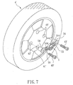
- FIGs 7 and 8 illustrate the second preferred embodiment of an electric generator 5' for use with a vehicle wheel 4' according to this invention, which is a modification of the first preferred embodiment.
- the metal wheel body 41' of the vehicle wheel 4' is formed with a plurality of fastener holes 42'.
- the electric generator 5' further includes a pair of anchor members 54, each of which is adapted to be disposed in and fastened to the vehicle wheel 4' at a respective one of the fastener holes 42' by means of a corresponding fastener 43' extending through a through hole 544 that is formed in the anchor member 54.
- Each of the anchor members 54 has a rim flange 542 adapted to be seated against the metal wheel body 41' of the vehicle wheel 4' outwardly of the respective one of the fastener holes 42'.
- Each of the mounting lugs 514 is disposed to lie against and is fastened by the corresponding fastener 55 to the rim flange 542 of a respective one of the anchor members 54. It is noted that each of the rim flanges 542 is formed with a plurality of positioning holes 545.
- the corresponding fastener 55 extends through the lug hole 515 in the mounting lug 514, and engages one of the positioning holes 545 in the anchor member 54 according to the size of the metal wheel body 41'.
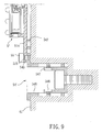
- FIG. 9 illustrates the third preferred embodiment of an electric generator 5" for use with a vehicle wheel according to this invention, which is a modification of the previous embodiments.
- each anchor member 54' includes an outer positioning tube 546 formed with the ring flange 542, and an inner anchoring seat 547 disposed in the positioning tube 546 and adapted to be fastened to the metal wheel body 41' of the vehicle wheel.
- the inner anchoring seat 547 has a sleeve portion positioned in the outer positioning tube 546 by means of a plurality of positioning fasteners 548, each of which extends through a through hole in the sleeve portion and into a corresponding slot formed in the outer positioning tube 546 such that the inner anchoring seat 547 is movable relative to the outer positioning tube 546 so as to suit vehicle wheels of varying thickness.
Landscapes
- Engineering & Computer Science (AREA)
- Mechanical Engineering (AREA)
- Power Engineering (AREA)
- Permanent Magnet Type Synchronous Machine (AREA)
- Connection Of Motors, Electrical Generators, Mechanical Devices, And The Like (AREA)
Priority Applications (1)
| Application Number | Priority Date | Filing Date | Title |
|---|---|---|---|
| EP04008383A EP1585211A1 (fr) | 2004-04-07 | 2004-04-07 | Générateur d'énergie électrique utilisé dans une roue de véhicule |
Applications Claiming Priority (1)
| Application Number | Priority Date | Filing Date | Title |
|---|---|---|---|
| EP04008383A EP1585211A1 (fr) | 2004-04-07 | 2004-04-07 | Générateur d'énergie électrique utilisé dans une roue de véhicule |
Publications (1)
| Publication Number | Publication Date |
|---|---|
| EP1585211A1 true EP1585211A1 (fr) | 2005-10-12 |
Family
ID=34896001
Family Applications (1)
| Application Number | Title | Priority Date | Filing Date |
|---|---|---|---|
| EP04008383A Withdrawn EP1585211A1 (fr) | 2004-04-07 | 2004-04-07 | Générateur d'énergie électrique utilisé dans une roue de véhicule |
Country Status (1)
| Country | Link |
|---|---|
| EP (1) | EP1585211A1 (fr) |
Cited By (1)
| Publication number | Priority date | Publication date | Assignee | Title |
|---|---|---|---|---|
| CN105954534A (zh) * | 2016-06-15 | 2016-09-21 | 吉林大学 | 基于面结构光和光敏电阻的运动汽车轮速检测系统 |
Citations (4)
| Publication number | Priority date | Publication date | Assignee | Title |
|---|---|---|---|---|
| US4075603A (en) * | 1976-10-04 | 1978-02-21 | Gould Inc. | Apparatus and method for indicating condition of a rotating body |
| WO1993004745A1 (fr) * | 1991-09-06 | 1993-03-18 | Nordica S.P.A. | Dispositif generateur d'energie destine notamment aux engins sportifs a roues |
| DE19648007A1 (de) * | 1996-11-20 | 1997-04-10 | Heiko Busse | Fahrzeugräder mit optischer Signalwirkung |
| EP0855784A1 (fr) * | 1997-01-22 | 1998-07-29 | Gunther Dr. Wulff | Dispositif de génération d'électricité pour roues de véhicules |
-
2004
- 2004-04-07 EP EP04008383A patent/EP1585211A1/fr not_active Withdrawn
Patent Citations (4)
| Publication number | Priority date | Publication date | Assignee | Title |
|---|---|---|---|---|
| US4075603A (en) * | 1976-10-04 | 1978-02-21 | Gould Inc. | Apparatus and method for indicating condition of a rotating body |
| WO1993004745A1 (fr) * | 1991-09-06 | 1993-03-18 | Nordica S.P.A. | Dispositif generateur d'energie destine notamment aux engins sportifs a roues |
| DE19648007A1 (de) * | 1996-11-20 | 1997-04-10 | Heiko Busse | Fahrzeugräder mit optischer Signalwirkung |
| EP0855784A1 (fr) * | 1997-01-22 | 1998-07-29 | Gunther Dr. Wulff | Dispositif de génération d'électricité pour roues de véhicules |
Cited By (1)
| Publication number | Priority date | Publication date | Assignee | Title |
|---|---|---|---|---|
| CN105954534A (zh) * | 2016-06-15 | 2016-09-21 | 吉林大学 | 基于面结构光和光敏电阻的运动汽车轮速检测系统 |
Similar Documents
| Publication | Publication Date | Title |
|---|---|---|
| US6765324B1 (en) | Electric generator for use with a vehicle wheel | |
| CN109866553B (zh) | 轮毂装置及车轮 | |
| CN101400537B (zh) | 线性驱动行驶系统以及汽车 | |
| US4761577A (en) | Wheel-mounted electrical power generator | |
| US6703716B2 (en) | Permanent magnet generator for bicycle light operation | |
| EP0982154A2 (fr) | Enjoliveur de roue | |
| AU2004272600A1 (en) | Wheel spinner assembly | |
| US4893877A (en) | Self-generated lighted hubcab | |
| EP0697759B1 (fr) | Moteur avec engrenage réducteur | |
| US5530630A (en) | Apparatus for lighting a vehicle wheel | |
| US20090082914A1 (en) | Electric motor and conversion system for manually powered vehicles | |
| US6749321B2 (en) | Automatic power-generating device for decorative lamps | |
| US6758042B2 (en) | Exhaust device with an electric generator | |
| WO2009015910A1 (fr) | Générateur pour bicyclette | |
| US6731072B2 (en) | Light generator for a rotatable object | |
| EP1585211A1 (fr) | Générateur d'énergie électrique utilisé dans une roue de véhicule | |
| CN111546978B (zh) | 带有主动式照明的用于机动车车轮的装饰罩 | |
| US7001053B1 (en) | Rotary motion powered light emitting diodes | |
| US20040257774A1 (en) | Heat-dissipating fan device with light-emitting capability | |
| US2253591A (en) | Pulley | |
| KR200342850Y1 (ko) | 차량용 알터네이터의 브러시룸 내부의 이물질 제거장치 | |
| EP4527640A1 (fr) | Dispositif de jante de roue | |
| US12603550B1 (en) | Land vehicle wheel mounted electricity generator | |
| KR200341996Y1 (ko) | 무게중심추를 이용한 소형발전기 및 그를 구비한 발광체 | |
| JPH1120762A (ja) | 自転車用点灯装置 |
Legal Events
| Date | Code | Title | Description |
|---|---|---|---|
| PUAI | Public reference made under article 153(3) epc to a published international application that has entered the european phase |
Free format text: ORIGINAL CODE: 0009012 |
|
| 17P | Request for examination filed |
Effective date: 20041021 |
|
| AK | Designated contracting states |
Kind code of ref document: A1 Designated state(s): AT BE BG CH CY CZ DE DK EE ES FI FR GB GR HU IE IT LI LU MC NL PL PT RO SE SI SK TR |
|
| AX | Request for extension of the european patent |
Extension state: AL HR LT LV MK |
|
| GRAP | Despatch of communication of intention to grant a patent |
Free format text: ORIGINAL CODE: EPIDOSNIGR1 |
|
| AKX | Designation fees paid |
Designated state(s): AT BE BG CH CY CZ DE DK EE ES FI FR GB GR HU IE IT LI LU MC NL PL PT RO SE SI SK TR |
|
| AXX | Extension fees paid |
Extension state: MK Payment date: 20041021 Extension state: LV Payment date: 20041021 Extension state: LT Payment date: 20041021 Extension state: AL Payment date: 20041021 |
|
| STAA | Information on the status of an ep patent application or granted ep patent |
Free format text: STATUS: THE APPLICATION IS DEEMED TO BE WITHDRAWN |
|
| 18D | Application deemed to be withdrawn |
Effective date: 20060321 |