EP1585226A2 - Système d'antenne pour la réception de télédiffusion terrestre - Google Patents
Système d'antenne pour la réception de télédiffusion terrestre Download PDFInfo
- Publication number
- EP1585226A2 EP1585226A2 EP05251573A EP05251573A EP1585226A2 EP 1585226 A2 EP1585226 A2 EP 1585226A2 EP 05251573 A EP05251573 A EP 05251573A EP 05251573 A EP05251573 A EP 05251573A EP 1585226 A2 EP1585226 A2 EP 1585226A2
- Authority
- EP
- European Patent Office
- Prior art keywords
- antenna
- signal
- probe
- antenna system
- signal amplifier
- Prior art date
- Legal status (The legal status is an assumption and is not a legal conclusion. Google has not performed a legal analysis and makes no representation as to the accuracy of the status listed.)
- Withdrawn
Links
Images


Classifications
-
- G—PHYSICS
- G09—EDUCATION; CRYPTOGRAPHY; DISPLAY; ADVERTISING; SEALS
- G09B—EDUCATIONAL OR DEMONSTRATION APPLIANCES; APPLIANCES FOR TEACHING, OR COMMUNICATING WITH, THE BLIND, DEAF OR MUTE; MODELS; PLANETARIA; GLOBES; MAPS; DIAGRAMS
- G09B19/00—Teaching not covered by other main groups of this subclass
- G09B19/18—Book-keeping or economics
-
- H—ELECTRICITY
- H04—ELECTRIC COMMUNICATION TECHNIQUE
- H04B—TRANSMISSION
- H04B1/00—Details of transmission systems, not covered by a single one of groups H04B3/00 - H04B13/00; Details of transmission systems not characterised by the medium used for transmission
- H04B1/06—Receivers
- H04B1/16—Circuits
- H04B1/18—Input circuits, e.g. for coupling to an antenna or a transmission line
-
- H—ELECTRICITY
- H01—ELECTRIC ELEMENTS
- H01Q—ANTENNAS, i.e. RADIO AERIALS
- H01Q9/00—Electrically-short antennas having dimensions not more than twice the operating wavelength and consisting of conductive active radiating elements
- H01Q9/04—Resonant antennas
- H01Q9/16—Resonant antennas with feed intermediate between the extremities of the antenna, e.g. centre-fed dipole
-
- A—HUMAN NECESSITIES
- A45—HAND OR TRAVELLING ARTICLES
- A45C—PURSES; LUGGAGE; HAND CARRIED BAGS
- A45C1/00—Purses; Money-bags; Wallets
- A45C1/06—Wallets; Notecases
-
- B—PERFORMING OPERATIONS; TRANSPORTING
- B43—WRITING OR DRAWING IMPLEMENTS; BUREAU ACCESSORIES
- B43K—IMPLEMENTS FOR WRITING OR DRAWING
- B43K23/00—Holders or connectors for writing implements; Means for protecting the writing-points
- B43K23/001—Supporting means
- B43K23/002—Supporting means with a fixed base
Definitions
- the present invention relates to an antenna system, and more particularly, but not exclsively, to an antenna system for terrestrial broadcasting designed to receive a television (TV) broadcast signal and deliver the television (TV) broadcast signal.
- TV television
- TV television
- NSC National Television Systems Committee
- ATSC Advanced Television Systems Committee
- VHF-H Very High Frequency-High
- An indoor or outdoor antenna is needed to receive the VHF-H broadcasts.
- An indoor antenna is more advantageous than an outdoor antenna in many aspects since the antenna must be connected to a digital set-top box to receive digital broadcasts
- FIG. 1 is an exemplary diagram showing the spectrum of frequencies within a VHF-H band, over which a dNTSC technique is applied.
- double sideband (DSB) modulation is used to mix an analog broadcast signal 100 and a digital broadcast signal 110 into a carrier.
- a NTSC format allows a carrier having a frequency f visc to carry the analog broadcast signal 100 having a frequency range of f cl to f ch
- a dNTSC format is used to additionally carry the digital broadcast signal 110, that is, to transmit a dNTSC data signal outside the frequency range of the analog broadcast signal 100.
- FIG. 2 is a table listing frequencies of the respective signals shown in FIG. 1 for VHF channels 7 through 13.
- the frequency of the carrier ranges from about 170 to about 220 megahertz (MHz) on the channels 7 through 13.
- the analog broadcast signal 100 has a bandwidth of 0.1 MHz while the dNTSC 110 has a bandwidth of 0.76 MHz.
- an indoor antenna for receiving a VHF-H signal including a digital broadcast signal is subject to space restrictions. Due to the space restrictions, it is difficult to determine the size of an antenna that varies according to a frequency band and realizes a dipole antenna. Thus, it is highly desirable to have an indoor antenna having a desired electrical length while occupying a small space to enable users to watch television broadcasts on Ultra High Frequency (UHF) band as well as VHF-H band.
- UHF Ultra High Frequency
- a broadcast signal benefits from being amplified in an antenna to improve its signal to noise ratio (SNR), since a higher SNR is achieved when the signal is amplified in the antenna before being sent to the next stage.
- SNR signal to noise ratio
- the antenna In the case of a dipole antenna, the antenna must be designed to solve problems arising between a balance circuit and an unbalance circuit for signal amplification.
- Embodiments of the present invention provide an antenna system designed to maximize signal propagation by compensating for an electrical length of an antenna probe by adding an inductor to the antenna probe and achieving wideband impedance matching between the antenna probe and a signal amplifier.
- an antenna system for terrestrial broadcasting comprising: a dipole antenna probe for receiving a broadcast signal; a signal amplifier for amplifying the received broadcast signal; an antenna matching unit for matching impedances between the antenna probe and the signal amplifier; an output matching unit for matching impedances between an output signal of the signal amplifier and an input terminal of a broadcast receiver to which the output signal is fed; and a bias extractor for converting power received from the broadcast receiver into power required for driving the signal amplifier and supplying the converted power to the signal amplifier.
- the broadcast signal may comprise data in a National Television Systems Committee (NTSC) video (dNTSC) broadcast signal transmitted over a Very High Frequency-High (VHF-H) band.
- NTSC National Television Systems Committee
- dNTSC Digital High Frequency-High
- VHF-H Very High Frequency-High
- the dipole antenna probe may comprise a probe with a variable length.
- the signal amplifier may comprise a monolithic microwave integrated circuit (MMIC) reducing noise contained in the received broadcast signal and amplifying the received broadcast signal.
- MMIC monolithic microwave integrated circuit
- the antenna matching unit may comprise a coil structure connected in series with a negative-probe of the antenna probe.
- the antenna matching unit may comprise a balun circuit.
- the balun circuit preferably comprises a ferrite core.
- the output matching unit may comprise a capacitor element.
- the bias extractor may comprise a plurality of passive circuit elements.
- the antenna system may further comprise a circuit protector for maintaining the power supplied from the broadcast receiver substantially constant and preventing electrostatic discharge.
- the circuit protector may comprise an arrestor.
- FIG. 3 is a block diagram of an antenna system according to an embodiment of the present invention.
- the antenna system 300 according to an embodiment of the present invention comprises an antenna probe 310 that receives a broadcast signal, an antenna matching unit 320 that performs impedance matching between the antenna probe 310 and a low noise amplifier 330, the low noise amplifier 330 that amplifies the broadcast signal in such a manner as to minimize noise contained in the broadcast signal and maximize gain over frequency band of the broadcast signal, an output matching unit 340 that performs impedance matching between the low noise amplifier 330 and an input terminal of a broadcast receiver (e.g., set-top box) 370 before a signal output at the low noise amplifier 330 is sent to the input terminal of the broadcast receiver 370, and a bias extractor 350 that receives power from the input terminal of the broadcast receiver 370 and then supplies a predetermined level of power to the low noise amplifier 330.
- a broadcast receiver e.g., set-top box
- the antenna system 300 may further comprise a circuit protector 360 that protects circuit elements making up the antenna system 300.
- the frequency band of the broadcast signal may include a Very High Frequency (VHF) band ranging from 30 to 300 megahertz (MHz) or an Ultra High Frequency (UHF) band ranging from 300 MHz to 3 gigahertz (GHz).
- VHF Very High Frequency
- UHF Ultra High Frequency
- the antenna probe 310 may be a dipole antenna.
- a probe connected to ground and a probe not connected to ground are referred to as a 'negative-probe' and a 'positive-probe', respectively.
- impedance matching is performed by the antenna matching unit 320 located between the antenna probe 310 and the low noise amplifier 330.
- a reactance component on the antenna probe 310 can be removed by modifying the structure of the antenna probe 310.
- a reactance component on the antenna probe 310 varies with a dipole length.
- one side of either the positive-probe or the negative-probe may be in the form of a coil (hereinafter referred to as a "loading coil"), which reduces capacitance of the antenna probe 310 and a voltage standing wave ratio (VSWR) of the dipole antenna.
- a loading coil a coil
- VSWR voltage standing wave ratio
- the antenna matching unit 320 uses the loading coil to match the impedance of the antenna probe 310 to the input impedance of the low noise amplifier 330 over the VHF or UHF band, thereby transmitting potential difference applied to the antenna probe 310 to the low noise amplifier 330 as much as possible while providing wideband impedance matching for reception over a wide range of frequencies.
- the antenna matching unit 320 includes a circuit used to couple a balance circuit of the dipole antenna to an unbalance circuit of a coaxial line, thereby preventing changes in radiation pattern and reception characteristics of the antenna due to unwanted surface current flowing in a coaxial line when coupling the balance circuit to the unbalance circuit.
- the low noise amplifier 330 Upon receipt of the broadcast signal from the antenna matching unit 320, the low noise amplifier 330 amplifies the same signal in such a manner as to maximize gain and minimize the noise temperature over a frequency band of the broadcast signal. In this way, the broadcast signal is amplified within the antenna system 300 before being sent to the broadcast receiver 370, thus minimizing distortion of the broadcast signal.
- the output matching unit 340 matches output impedance of the low noise amplifier 330 to tuner impedance of the broadcast receiver 370.
- the amplified signal After the broadcast signal received from the antenna probe 310 passes through the antenna matching unit 320 and is amplified by the low noise amplifier 330, the amplified signal then passes through the output matching unit 340 to a tuner of the broadcast receiver 370.
- the bias extractor 350 converts power from the broadcast receiver 370 into a level of power required for driving the low noise amplifier 330.
- the antenna system 300 may further comprise the circuit protector 360 that protects the circuit elements forming the antenna system 300 against spike noise resulting from static electricity or ground potential difference. While FIG. 3 shows that the circuit protector 360 is located at a position that enables the reception of power from the broadcast receiver 370, the circuit protector 360 may be located at another position. For example, a separate circuit protector may also be positioned between the antenna matching unit 320 and the low noise amplifier 330 so as to protect the low noise amplifier 330.
- the broadcast signal or power may be transmitted between the antenna system 300 and the broadcast receiver 370 via a single cable.
- FIG. 4 is a circuit diagram of an antenna system according to an embodiment of the present invention.
- An antenna probe 310 is a dipole antenna probe consisting of a positive-probe 312 and a negative-probe 314.
- a loading coil 316 described as above may be connected to either an input terminal 332 or a ground terminal 334 of a low noise amplifier 330.
- the loading coil 316 may be connected to the ground terminal 334.
- the lengths of the positive-probe 312 and the negative-probe 314 may be adjusted to improve the reception sensitivity of a broadcast signal.
- an input impedance Z in of the dipole antenna is expressed as 20-j314, the final input impedance Z in of 20 is obtained by creating +j314 component, which can be achieved by connecting the loading coil 316 in series to the negative-probe 314.
- 314 2*3.14*200*10 6 *L when frequency f is 200 MHz.
- Solving the equation results in the inductance L of 250 nH.
- the loading coil 316 has the number of turns of 10, a thickness of 1.1 mm, and an inside diameter of 5.2 mm.
- an input impedance of the dipole antenna eventually becomes 20.
- an impedance-matching transformer with a 1:2.5 turns ratio is used to match the 50 ⁇ for the mutual impedance matching.
- a separate circuit is preferably used to solve problems caused by coupling a balance circuit of a dipole antenna with an unbalance circuit of a coax line.
- a balun circuit in the antenna matching unit 320 is used to enable the balance circuit to be coupled to the unbalance circuit or vice versa.
- the balun circuit is usually bulky in size and has a narrow bandwidth.
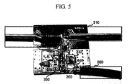
- the balun circuit may be realized using a ferrite core as shown in FIG. 5. Meanwhile, the balun circuit may be connected to either input or output terminal of the low noise amplifier 330, preferably, to the input terminal of the low noise amplifier 330, so as to solve an imbalance between the balance circuit of the antenna probe 310 and the unbalance circuit of the coax line.
- Gali-52LNA Monolithic Microwave IC MMIC
- Ga-52LNA' the low noise amplifier 330
- the bias extractor 350 makes the magnitudes of power and current supplied by the broadcast receiver 370 to be equal to 4.4 V and 50 mA.
- the broadcast receiver 370 is a set-top box and a voltage supplied from the set-top box is 12 V direct current (DC).
- the bias extractor 350 is comprised of a resistor, a capacitor, and an inductor.
- Inductor L1 used for bias extraction must have an impedance greater than 50 ⁇ , and preferably greater than 500 ⁇ .
- a solution to this inequality is L >398nH.
- the inductor L1 exhibits the same characteristics when the range of inductance is from 350 nH to 3 uH.
- it is preferably designed to provide for inductance of less than 3 uH and resist current of 100 mA.
- a 2.7 uH chip inductor that is easy to mount is used.
- Shunt chip capacitors C3, C4 and C5 act to block radio waves that travel through a bias circuit and is reflected toward the low noise amplifier 330.
- the capacitors C3, C4, and C5 have capacitances of 1,000 pF, 100 pF, and 10 nF, respectively.
- the capacitor C2 is used to remove an instantaneous pulse occurring when a coaxial cable 380 shown in FIG. 4 is connected to the broadcast receiver 370. Since it is desirable to use a capacitor having a large capacitance, a 10-uF tantal capacitor is used in the illustrative embodiment. Referring to FIG.
- an output matching unit 340 used to properly transfer the broadcast signal amplified by the low noise amplifier 330 is realized using the DC blocking capacitor C 1 that prevents the transfer of DC signals.
- the capacitance of the capacitor C1 is set such that its impedance X is much less than 50 ⁇ , preferably, less than 5 ⁇ over an available frequency range.
- the capacitor C1 since with increasing frequency, the capacitor C1 becomes self-resonant and cannot maintain its own characteristics, it is desirable to use a very small capacitor having a high self-resonant point or a capacitor having a slightly lower capacitance.
- the capacitor C1 has capacitance of 100 pF since its insertion loss is less than 0.3 dB over the available frequency range.
- a circuit protector 360 protects the low noise amplifier 330 by eliminating electrostatic discharge originating from the inner wire of the coaxial cable 380 or the positive-probe 312.
- the circuit protector 360 is constructed using an arrestor.
- FIG. 5 shows an antenna system in which the circuits shown in FIG. 4 are placed on a printed circuit board (PCB) according to an embodiment of the present invention.
- the coaxial cable 380 receives power from the broadcast receiver 370 through its end (not shown) connected to the broadcast receiver 370 for supply to the low noise amplifier 330 and transmits a broadcast signal amplified by the low noise amplifier 330 to the broadcast receiver 370.
- An antenna system is designed with a reduced length of a dipole antenna suitable for indoor use and to amplify a broadcast signal fed through an antenna probe before sending it to a broadcast receiver such as a set-top box, thereby minimizing distortion in the broadcast signal.
Landscapes
- Engineering & Computer Science (AREA)
- Business, Economics & Management (AREA)
- Entrepreneurship & Innovation (AREA)
- Computer Networks & Wireless Communication (AREA)
- Signal Processing (AREA)
- General Business, Economics & Management (AREA)
- Economics (AREA)
- Development Economics (AREA)
- Accounting & Taxation (AREA)
- Physics & Mathematics (AREA)
- Educational Administration (AREA)
- Educational Technology (AREA)
- General Physics & Mathematics (AREA)
- Theoretical Computer Science (AREA)
- Input Circuits Of Receivers And Coupling Of Receivers And Audio Equipment (AREA)
- Variable-Direction Aerials And Aerial Arrays (AREA)
- Details Of Aerials (AREA)
Applications Claiming Priority (2)
| Application Number | Priority Date | Filing Date | Title |
|---|---|---|---|
| KR2004024145 | 2004-04-08 | ||
| KR1020040024145A KR100621135B1 (ko) | 2004-04-08 | 2004-04-08 | 지상파 방송을 위한 안테나 시스템 |
Publications (2)
| Publication Number | Publication Date |
|---|---|
| EP1585226A2 true EP1585226A2 (fr) | 2005-10-12 |
| EP1585226A3 EP1585226A3 (fr) | 2006-08-09 |
Family
ID=34910097
Family Applications (1)
| Application Number | Title | Priority Date | Filing Date |
|---|---|---|---|
| EP05251573A Withdrawn EP1585226A3 (fr) | 2004-04-08 | 2005-03-16 | Système d'antenne pour la réception de télédiffusion terrestre |
Country Status (5)
| Country | Link |
|---|---|
| US (1) | US6950077B1 (fr) |
| EP (1) | EP1585226A3 (fr) |
| KR (1) | KR100621135B1 (fr) |
| CN (1) | CN1681215A (fr) |
| AU (1) | AU2005200292B2 (fr) |
Families Citing this family (10)
| Publication number | Priority date | Publication date | Assignee | Title |
|---|---|---|---|---|
| US20070085754A1 (en) * | 2005-10-18 | 2007-04-19 | Nokia Corporation | RF front-end architecture for a separate non-50 ohm antenna system |
| WO2012013240A1 (fr) * | 2010-07-30 | 2012-02-02 | Laird Technologies Ab | Dispositif d'antenne auxiliaire, ensemble d'antennes et dispositif de radiocommunication portatif |
| CN102420353B (zh) * | 2010-09-28 | 2015-08-05 | 宏达国际电子股份有限公司 | 天线模块 |
| TWI431935B (zh) | 2010-09-28 | 2014-03-21 | Htc Corp | 天線模組 |
| KR101857214B1 (ko) * | 2011-12-21 | 2018-05-14 | 한국전자통신연구원 | 다채널 빔스캔 수신기 |
| US9571037B2 (en) * | 2014-10-31 | 2017-02-14 | Skyworks Solutions, Inc. | Diversity receiver front end system with impedance matching components |
| US10050694B2 (en) | 2014-10-31 | 2018-08-14 | Skyworks Solution, Inc. | Diversity receiver front end system with post-amplifier filters |
| US9893752B2 (en) | 2014-10-31 | 2018-02-13 | Skyworks Solutions, Inc. | Diversity receiver front end system with variable-gain amplifiers |
| US10009054B2 (en) | 2015-05-28 | 2018-06-26 | Skyworks Solutions, Inc. | Impedance matching integrous signal combiner |
| CN110323553B (zh) * | 2019-04-01 | 2021-07-16 | 深圳三星通信技术研究有限公司 | 天线的辐射单元及天线 |
Family Cites Families (14)
| Publication number | Priority date | Publication date | Assignee | Title |
|---|---|---|---|---|
| US4115778A (en) * | 1976-11-18 | 1978-09-19 | Jfd Electronics Corporation | Electronic solid state FM dipole antenna |
| US4228544A (en) * | 1978-01-19 | 1980-10-14 | Guyton James H | Antenna system using antenna base impedance transforming means |
| DE3150958A1 (de) * | 1981-12-23 | 1983-07-14 | FTE maximal Fernsehtechnik und Elektromechanik GmbH & Co KG, 7130 Mühlacker | Ukw-zimmerantenne |
| US5089829A (en) * | 1989-12-22 | 1992-02-18 | Yokowo Mfg. Co., Ltd | Antenna device shared by three kinds of waves |
| GB2260871B (en) * | 1991-10-25 | 1995-06-28 | Marconi Gec Ltd | R.F. Power amplifier |
| US6097347A (en) * | 1997-01-29 | 2000-08-01 | Intermec Ip Corp. | Wire antenna with stubs to optimize impedance for connecting to a circuit |
| JP2000013267A (ja) * | 1998-06-19 | 2000-01-14 | Pioneer Electron Corp | アンテナブースタ |
| JP3851463B2 (ja) | 1999-02-12 | 2006-11-29 | Dxアンテナ株式会社 | U/v共用tv受信用アンテナ |
| US6429821B1 (en) | 1999-10-12 | 2002-08-06 | Shakespeare Company | Low profile, broad band monopole antenna with inductive/resistive networks |
| US7161476B2 (en) * | 2000-07-26 | 2007-01-09 | Bridgestone Firestone North American Tire, Llc | Electronic tire management system |
| KR200217332Y1 (ko) | 2000-11-03 | 2001-03-15 | 안동식 | 텔레비전 수신카드용 평면형 광대역 대수 주기 다이폴안테나 |
| US6574510B2 (en) | 2000-11-30 | 2003-06-03 | Cardiac Pacemakers, Inc. | Telemetry apparatus and method for an implantable medical device |
| DE10114769B4 (de) | 2001-03-26 | 2015-07-09 | Heinz Lindenmeier | Aktive Breitbandempfangsantenne |
| KR100859876B1 (ko) * | 2002-05-28 | 2008-09-24 | 삼성전자주식회사 | 세그먼트동기정보를 이용하여 등화를 수행할 수 있는vsb수신기의 등화기 |
-
2004
- 2004-04-08 KR KR1020040024145A patent/KR100621135B1/ko not_active Expired - Fee Related
-
2005
- 2005-01-25 AU AU2005200292A patent/AU2005200292B2/en not_active Ceased
- 2005-03-10 US US11/075,766 patent/US6950077B1/en not_active Expired - Fee Related
- 2005-03-15 CN CNA2005100539770A patent/CN1681215A/zh active Pending
- 2005-03-16 EP EP05251573A patent/EP1585226A3/fr not_active Withdrawn
Also Published As
| Publication number | Publication date |
|---|---|
| AU2005200292A1 (en) | 2005-10-27 |
| KR100621135B1 (ko) | 2006-09-13 |
| US20050225494A1 (en) | 2005-10-13 |
| AU2005200292B2 (en) | 2006-02-02 |
| EP1585226A3 (fr) | 2006-08-09 |
| KR20050099070A (ko) | 2005-10-13 |
| US6950077B1 (en) | 2005-09-27 |
| CN1681215A (zh) | 2005-10-12 |
Similar Documents
| Publication | Publication Date | Title |
|---|---|---|
| US6686882B2 (en) | Apparatus and method for transferring DC power and RF energy through a dielectric for antenna reception | |
| US8010061B2 (en) | Combining multimedia signaling and wireless network signaling on a common communication medium | |
| US6950077B1 (en) | Antenna system for terrestrial broadcasting | |
| JP2003143028A (ja) | 低雑音コンバータ | |
| WO2011004514A1 (fr) | Dispositif radio portable | |
| US9124091B2 (en) | Surge protector for a transmission line connector | |
| CN106412467A (zh) | 一种低通滤波器及lnb模块及信号处理方法 | |
| US20140376724A1 (en) | Headset loop antenna for audio devices | |
| JP2001204016A (ja) | 衛星チューナの入力回路 | |
| US20080090535A1 (en) | Amplifier circuit and receiving device | |
| US20180152154A1 (en) | Radio frequency power amplifier and wireless communications device | |
| US20050107044A1 (en) | Active antenna with amplifier | |
| US7796957B2 (en) | Impedance transformation in a duplexer using a transmission line | |
| KR100921986B1 (ko) | 핀다이오드를 이용한 슬로프 회로 및 그를 이용한 위성증폭기 | |
| EP1523098B1 (fr) | Récepteur comprenant une compensation de linéarité dans la bande de réception | |
| US6424306B1 (en) | Windshield antenna | |
| EP1061659A2 (fr) | Récepteur multibande | |
| CN213584159U (zh) | 一种天线增益电路、装置及系统 | |
| US7382196B2 (en) | UHF active antenna amplifier for digital video broadcast (DVB) receiver and related DVB device | |
| KR100719126B1 (ko) | 카운터폴에 로딩코일이 구비된 능동안테나 | |
| KR19980035674U (ko) | 무선호출데이터 전송시스템의 단말국 옥외 정합장치 | |
| KR960003991Y1 (ko) | 고주파신호 정합장치 | |
| KR20050011072A (ko) | 윌킨슨 전력분배기를 이용하여 위성방송신호의 전력을분배하는 위성방송수신기 | |
| Zhang et al. | Earphone antenna for handheld digital audio broadcasting receivers | |
| Zhang et al. | Earphone antenna for handheld digital audio broadcasting |
Legal Events
| Date | Code | Title | Description |
|---|---|---|---|
| PUAI | Public reference made under article 153(3) epc to a published international application that has entered the european phase |
Free format text: ORIGINAL CODE: 0009012 |
|
| 17P | Request for examination filed |
Effective date: 20050405 |
|
| AK | Designated contracting states |
Kind code of ref document: A2 Designated state(s): AT BE BG CH CY CZ DE DK EE ES FI FR GB GR HU IE IS IT LI LT LU MC NL PL PT RO SE SI SK TR |
|
| AX | Request for extension of the european patent |
Extension state: AL BA HR LV MK YU |
|
| PUAL | Search report despatched |
Free format text: ORIGINAL CODE: 0009013 |
|
| AK | Designated contracting states |
Kind code of ref document: A3 Designated state(s): AT BE BG CH CY CZ DE DK EE ES FI FR GB GR HU IE IS IT LI LT LU MC NL PL PT RO SE SI SK TR |
|
| AX | Request for extension of the european patent |
Extension state: AL BA HR LV MK YU |
|
| 17Q | First examination report despatched |
Effective date: 20061010 |
|
| AKX | Designation fees paid | ||
| REG | Reference to a national code |
Ref country code: DE Ref legal event code: 8566 |
|
| RBV | Designated contracting states (corrected) |
Designated state(s): DE ES GB IT NL |
|
| GRAP | Despatch of communication of intention to grant a patent |
Free format text: ORIGINAL CODE: EPIDOSNIGR1 |
|
| STAA | Information on the status of an ep patent application or granted ep patent |
Free format text: STATUS: THE APPLICATION IS DEEMED TO BE WITHDRAWN |
|
| 18D | Application deemed to be withdrawn |
Effective date: 20081104 |