EP1585228B1 - Mehrbenutzer-demodulationsvorrichtung, empfangsvorrichtung und mehrkanal-demodulationsverfahren - Google Patents
Mehrbenutzer-demodulationsvorrichtung, empfangsvorrichtung und mehrkanal-demodulationsverfahren Download PDFInfo
- Publication number
- EP1585228B1 EP1585228B1 EP20050012393 EP05012393A EP1585228B1 EP 1585228 B1 EP1585228 B1 EP 1585228B1 EP 20050012393 EP20050012393 EP 20050012393 EP 05012393 A EP05012393 A EP 05012393A EP 1585228 B1 EP1585228 B1 EP 1585228B1
- Authority
- EP
- European Patent Office
- Prior art keywords
- fingers
- unit
- user
- units
- paths
- Prior art date
- Legal status (The legal status is an assumption and is not a legal conclusion. Google has not performed a legal analysis and makes no representation as to the accuracy of the status listed.)
- Expired - Lifetime
Links
Images







Classifications
-
- H—ELECTRICITY
- H04—ELECTRIC COMMUNICATION TECHNIQUE
- H04B—TRANSMISSION
- H04B1/00—Details of transmission systems, not covered by a single one of groups H04B3/00 - H04B13/00; Details of transmission systems not characterised by the medium used for transmission
- H04B1/69—Spread spectrum techniques
- H04B1/707—Spread spectrum techniques using direct sequence modulation
- H04B1/7097—Interference-related aspects
- H04B1/711—Interference-related aspects the interference being multi-path interference
- H04B1/7115—Constructive combining of multi-path signals, i.e. RAKE receivers
- H04B1/7117—Selection, re-selection, allocation or re-allocation of paths to fingers, e.g. timing offset control of allocated fingers
-
- H—ELECTRICITY
- H04—ELECTRIC COMMUNICATION TECHNIQUE
- H04B—TRANSMISSION
- H04B1/00—Details of transmission systems, not covered by a single one of groups H04B3/00 - H04B13/00; Details of transmission systems not characterised by the medium used for transmission
- H04B1/69—Spread spectrum techniques
- H04B1/707—Spread spectrum techniques using direct sequence modulation
- H04B1/7097—Interference-related aspects
- H04B1/711—Interference-related aspects the interference being multi-path interference
- H04B1/7115—Constructive combining of multi-path signals, i.e. RAKE receivers
- H04B1/712—Weighting of fingers for combining, e.g. amplitude control or phase rotation using an inner loop
-
- H—ELECTRICITY
- H04—ELECTRIC COMMUNICATION TECHNIQUE
- H04B—TRANSMISSION
- H04B2201/00—Indexing scheme relating to details of transmission systems not covered by a single group of H04B3/00 - H04B13/00
- H04B2201/69—Orthogonal indexing scheme relating to spread spectrum techniques in general
- H04B2201/707—Orthogonal indexing scheme relating to spread spectrum techniques in general relating to direct sequence modulation
- H04B2201/70707—Efficiency-related aspects
- H04B2201/7071—Efficiency-related aspects with dynamic control of receiver resources
Definitions
- the present invention relates to a receiving apparatus.
- a rake receiving system that receives spectrum-spread signals is well known and is used as a communications system that has superior characteristics in interference-resistant and interruption-resistant reception.
- An example of the rake receiving system is disclosed in Japanese Patent Laid-Open Publication No. H11-8606.
- the rake receiving apparatus comprises a plurality of fingers to demodulate each path of one modulated reception signal. Demodulated signals are obtained in a rake combining unit by rake-combining the output signals of the fingers.
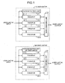
- Fig. 1 explains the structure of a rake receiving apparatus in a conventional base transceiver station.
- a user unit (#1) 110 and a user unit (#2) 120 have an identical structure, and each receives a signal transmitted from different mobile station terminals. The sequence of operations in the user unit (#1) 110 is explained hereafter.
- the signal received at the user unit (#1) 110 is input to a path detecting unit 111, and the path detecting unit 111 detects each path.
- the information relating to a single path or a plurality of paths that are detected is conveyed separately to eight fingers 112-1 to 112-8. Each path is then separated and demodulated at the fingers 112-1 to 112-8 according to the path information obtained from the reception signal.
- These demodulated signals are input to a rake combining unit 113, and the rake combining unit 113 combines the signals. Since there are eight fingers, a maximum of eight paths can be combined in the example shown in Fig. 1.
- the rake combining unit and the fingers are connected in a fixed manner. For instance, in the case where the number of paths in the transmission line is greater than the preset number of fingers, the paths exceeding the number of fingers cannot be used in the rake combining. Hence, in order to prevent such problems, it is necessary to provide extra fingers beforehand. On the other hand, if a sufficient number of fingers are provided beforehand, some fingers can not be used in the rake combining when the number of fingers in the transmission line is fewer than the number of fingers, finding a problem of inefficient usage of the fingers.
- WO-A-9430025 shows a rake-type CDMA base station receiver equipment, comprising a number of correlators each having a received singnal as its input, a number of diversity combiners and means for measuring the quality of the received signal.
- WO-A-9413066 discloses a method and an apparatus for computing a scalar projection of a vector onto another vector comprising a bit truncator to reduce bit handling problems.
- US-A-5,764,687 shows a rake receiver which separates a signal processing based on the period over which the processing is performed by a single time-shared multiply-accumulate data path that services multiple finger front ends and a searcher front end.
- the receiving apparatus includes a plurality of fingers that separately demodulate paths of one reception signal among a plurality of reception signals, a control unit that determines whether either of a group of the fingers and all the fingers demodulate paths of a first reception signal or paths of a second reception signal, a first rake combining unit that rake-combines, based on the allocation of fingers by the control unit, the demodulated signals output from the fingers corresponding to the first reception signal, and a second rake combining unit that rake-combines, based on the allocation of fingers by the control unit, the demodulated signals output from the fingers corresponding to the second reception signal, wherein the first rake combining unit includes an overflow suppressing unit that suppresses an addition overflow when combining the demodulated signals from the fingers.
- the overflow suppressing unit (19a) functions based on number of fingers allocated by the control unit.
- Fig. 2 is a block diagram of a receiving apparatus according to a first embodiment.
- This receiving apparatus includes a demodulating apparatus that has fingers belonging to two user units, used for demodulating signals, and that allows one of the fingers belonging to one user unit to be used for the other user unit.
- the structure and function of a user unit (#1) 10a is explained below.
- the structure as well as the function of a user unit (#2) 10b is identical to that of the user unit (#1) 10a.
- the user unit (#1) 10a includes a path detecting unit 11a, a plurality of fingers 12-1 to 12-8, and a rake combining unit 13a.
- a reception signal that is input to the user unit (#1) 10a is input to the path detecting unit 11a.
- the path detecting unit 11a detects number of paths of the reception signal.
- Information relating to a single detected path or a plurality of detected paths is conveyed separately to the corresponding fingers 12-1 to 12-8.
- the fingers 12-1 to 12-8 then demodulate each path separately based on the path information obtained from the reception signal. This separately demodulated signal is input to the rake combining unit 13a.
- the rake combining unit 13a then combines the demodulated signals, and outputs a combined signal as the output of the user unit (#1) 10a.
- a control unit 1 that controls the user units (#1) 10a, (#2) 10b is connected to change-over switches 14a, 15a, 16a.
- the control unit 1 controls switching of the change-over switches 14a, 15a, 16a in such a way that the eighth finger 12-8 out of the fingers 12-1 to 12-8 belonging to the user unit (#1) 10a can be used in the user unit (#2) 10b.
- the change-over switch 14a is a device that switches between the user unit (#1) 10a and the user unit (#2) 10b in such a way that the reception signal that is input the finger (#8) 12-8 according to the control of the control unit 1 is either from the user unit (#1) 10a or the user unit (#2) 10b.
- the change-over switch 15a is a device that switches between the path detecting unit 11a of the user unit (#1) 10a and the path detecting unit 11b of the user unit (#2) 10b in such a way that the path information that is input to the finger (#8) 12-8 according to the control of the control unit 1 is either from the path detecting unit 11a or the path detecting unit 11b.
- the change-over switch 16a is a device that switches between a rake combining unit 13a of the user unit (#1) 10a and a rake combining unit 13b of the user unit (#2) 10b in such a way that the demodulated signal output from the finger (#8) according to the control of the control unit 1 is input to either the rake combining unit 13a or the rake combining unit 13b.
- the control unit 1, the fingers 12-1 to 12-16, and the rake combining units 13a, 13b are examples of a control unit, a demodulating unit, and a combining unit, respectively.
- the fingers 12-1 to 12-16 can also be configured as a finger device.
- the finger 12-8 of the user unit (#1) 10a demodulates, based on the path information conveyed from the path detecting unit 11b of the user unit (#2) 10b via the change-over switch 15a, the reception signal of the user unit (#2) 10b input via the change-over switch 14a.
- the output of this demodulation is input to the rake combining unit 13b of the user unit (#2) 10b via the change-over switch 16a.
- the rake combining unit 13b then combines this output with the output of the fingers 12-9 to 12-16 of the user unit (#2) 10b.
- the user unit (#1) 10a can use seven (8-1) fingers and the user unit (#2) 10b can use nine (8+1) fingers. Consequently, in communications carried out by the user unit (#1) 10a, a maximum of seven paths can be demodulated, while in communications carried out by the user unit (#2) 10b, a maximum of nine paths can be demodulated.
- the finger 12-8 of the user unit (#1) 10a demodulates, based on the path information conveyed from the path detecting unit 11a of the user unit (#1) 10a via the change-over switch 15a, the reception signals of the user unit (#1) 10a input via the change-over switch 14a and the output of this demodulation is input to the rake combining unit 13a of the user unit (#1) 10a via the change-over switch 18a.
- the rake combining unit 13a then combines this output with the output of the other fingers 12-1 to 12-7 of the user unit (#1) 10a.
- both the user units (#1) 10a and (#2) 10b can use eight fingers each. Consequently, a maximum of eight paths can be demodulated in communications carried out by the user unit (#1) 10a as well as by the user unit (#2) 10b.
- Eight fingers are used in the present embodiment, however, any number of fingers can be used in each user unit as required. Furthermore, although only two user units are employed in the present embodiment, any number of user units can be employed with a facility to switch one finger or a plurality of fingers between the user units.
- control of the control unit 1 over the change-over switches 14a, 15a, and 16a can be carried out anyhow as long as the proper number of fingers is allocated to the user unit according to the communication requirements of the user unit. For instance, the control can be carried out based on the following criteria.
- this kind of decision and control can be achieved by using known control apparatuses and software technology.
- the output of the control signal can be controlled in such a way that the change-over switch is switched to the user unit with digitized assessment standard values (signal-to-noise ratio, required service quality, number of paths etc.) greater than the preset values or to the user unit with the digitized values greater than those of other user units after comparison with the corresponding user units.
- digitized assessment standard values signal-to-noise ratio, required service quality, number of paths etc.
- only one finger is switchable between a plurality of user units and the finger is switchable between only two user units.
- the finger is switchable between only two user units.
- Fig. 3 is a block diagram of a receiving apparatus according to a second embodiment. As shown in Fig. 3, the parts identical or equivalent to those shown in Fig. 2 are assigned the same reference numerals. Besides, the structure of fingers 12-17 to 12-32, which are extended compared with the first embodiment, two rake combining units 13c, 13d, etc. are identical to corresponding fingers 12-1 to 12-16, the rake combining unit 13a, 13b, etc., respectively. A control unit 1 is connected to change-over switches 14c, 15c, and 16c. The control unit 1 controls the switching of the change-over switches 14c, 15c, and 16c in such a way that the 32 fingers 12-1 to 12-32 can be used for any of the user units.
- the change-over switch 14c is a device that inputs, according to the control of the control unit 1, the reception signals of user units (#1) to (#4) to the corresponding fingers 12-1 to 12-32, by connecting to the fingers 12-1 to 12-32 in a switchable manner.
- the change-over switch 15a is a device that inputs, according to the control of the control unit 1, a plurality of path information of path detecting units 11a to 11d to the corresponding fingers 12-1 to 12-32 by connecting to the fingers 12-1 to 12-32 in a switchable manner.
- the change-over switch 16a is a device that inputs, according to the control of the control unit 1, the demodulated signals that are output from the fingers 12-1 to 12-32 to any of the rake combining units 13a to 13d of the corresponding user units by connecting in a switchable manner to any of the rake combining units 13a to 13d.
- the change-over switches 14c, 15c, and 16c connect, according to the instruction from the control unit 1, the fingers 12-1 to 12-12 to the user unit (#1), the fingers 12-13 to 12-17 to the user unit (#2), the fingers 12-18 to 12-23 to the user unit (#3), and the fingers 12-24 to 12-32 to the user unit (#4).
- the fingers 12-1 to 12-12 demodulate, based on the path information conveyed by the path detecting unit 11a of the user unit (#1) via the change-over switch 15c, the reception signals of the user unit (#1) that are input via the change-over switch 14c.
- the rake combining unit 13a then receives twelve output signals from the twelve fingers 12-1 to 12-12 via the change-over switch 16c and combines these output signals.
- the fingers 12-13 to 12-17 demodulate, based on the path information conveyed by the path detecting unit 11b of the user unit (#2) via the change-over switch 15c, the reception signals of the user unit (#2) that are input via the change-over switch 14c.
- the rake combining unit 13b of the user unit (#2) then receives five output signals from the five fingers 12-13 to 12-17 via the change-over switch 16c and combines these output signals.
- the user unit (#3) combines six output signals and the user unit (#4) combines nine output signals.
- a maximum of twelve paths can be demodulated in the communication carried out by the user unit (#1)
- a maximum of five paths can be demodulated in the communication carried out by the user unit (#2)
- a maximum of six paths can be demodulated in the communication carried out by the user unit (#3)
- a maximum nine of paths can be demodulated in the communication carried out by the user unit (#4).
- the number of fingers allocated to each user unit can be freely modified, by switching the change-over switches 14c, 15c, and 16c according to the control of the control unit 1 and by modifying the distribution of the 32 fingers among the user units.
- the number of user units is taken as four. However, this number is just an example and any number of user units can be employed. Similarly, although the number of fingers is taken as 32, this number also can be modified as required.
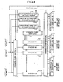
- Fig. 4 is an example of a third embodiment, wherein the number of allocated fingers is modified according to the number of detected paths present in each user unit.
- Path detecting units 11a to 11d of user units (#1) to (#4) are connected to a control unit 1.
- the path detecting units 11a to 11d notify the result of path detection to the control unit 1.
- the control unit 1 determines, from the number of paths and the power of the paths notified by the path detecting units 11a to 11d of the user units (#1) to (#4) respectively, the number of fingers to be allocated to each user unit.
- the control unit 1 then controls change-over switches 14c, 15c, and 16c and allocates the determined number of fingers to each user unit.
- the fingers 12-1 to 12-32 after determining the number of fingers proportional to the number of paths in which the reception level is greater than an acceptable value.
- Fig. 5 is a flowchart that explains an example of the method of finger allocation of the control unit 1 shown in Fig. 4.
- the path detecting units 11a to 11d of the user units (#1) to (#4) detect number of paths as well as the value of the power of each path (step S1). Based on this path information, the control unit 1 determines a path having the maximum power for each user unit (step S2). The control unit 1 then allocates these paths, based on the determined maximum power, to fingers 12-n, respectively (step S3). As the number of user units shown in Fig.
- the path detecting units 11a to 11d and rake combining units 13a to 13d are also allocated in the same manner.
- control unit 1 controls the change-over switches in such a way that the change-over switch 14c connects the finger 12-1 with the input of the user unit (#1), the change-over switch 15c connects the finger 12-1 with the path detecting unit 11a, and the change-over switch 16c connects the finger 12-1 with the rake combining unit 13a.
- the finger 12-1 separately demodulates the path that has the maximum power as determined based on the path information obtained from the path detecting unit 11a.
- the remaining fingers to which the paths are not allocated in step S3 are allocated to the remaining paths.
- the fingers that remain after the paths with the maximum powers are allocated to each user unit in step S3 is 28.
- the remaining paths of all the user units are sorted in descending order of the power (step S4) and are allocated to the fingers preferentially in descending order that is, from the finger 12-32 to 12-5 (step S5). In this way, at least one path is allocated to each user unit.
- the allocation of the path detecting units and the rake combining units etc. is also carried out by switching the change-over switches 14c, 15c, and 16c, as explained in step S3.
- the allocation of the paths that remain after the path with the maximum power has been allocated is carried out in the descending order of their power and regardless of the user unit.
- the remaining paths can be allocated preferentially to the user unit that has the path with the least maximum power among the paths with the maximum power of all the user units.
- Fig. 6 is an example of a fourth embodiment in which a flag that indicates a priority of communication is included in the transmitted data.
- the flag is detected at the time of demodulation and the number of fingers to be allocated is modified based on the priority of communication indicated by the flag.
- the reference numerals 17a to 17d represent priority data extracting units that extract the flag, which indicates the priority included in the demodulating data.
- Rake combining units 13a to 13d of user units (#1) to (#4) are connected to a control unit 1 via the priority data extracting units 17a to 17d.
- the control unit 1 compares the priority of communication in each user unit received from the priority data extracting units 17a to 17d.
- the control unit 1 controls allocation of fingers in such a way that more fingers are allocated to the user units that carry out the communication of higher priority and controls the change-over switches 14c, 15c, and 16c for allocating the determined number of fingers to each user unit.
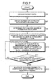
- Fig. 7 is a flowchart that explains an example of allocating fingers controlled by the control unit 1 shown in Fig. 6.
- the priority data extracting units 17a to 17d extract the priority data of each user unit from the output of the corresponding rake combining units 13a to 13d and the control unit 1 then obtains these priority data (step S6).
- the priority data has two types of priorities namely 'high' priority and 'low' priority.
- the path detecting units 111a to 11d of the user units (#1) to (#4) detect number of paths as well as power of each path (step S7).
- the control unit 1 retrieves a path having the maximum power for each user unit (step S8) and then allocates these paths to corresponding fingers (one finger per each user unit) (step S9).
- the remaining fingers are allocated to the rest of the paths of each user unit.
- the fingers are allocated first to the user units with a 'high' priority, so that the user units having 'high' priority are allocated more fingers. That means, in the user units having a 'high' priority data, the paths are allocated to the fingers in descending order of the power.
- the maximum number of fingers to be allocated to each user unit is limited to M, and once that number is reached, the remaining paths are not allocated (step S10, step S11).
- the remaining paths are allocated to the fingers of the user units having a 'low' priority data (step S12).
- the allocation of each path to each finger in steps S9, S10, and S12 is controlled by switching the change-over switches 14c, 15c and 16c, in the same manner as the step S3 in Fig. 5.
- control unit 1 allocates the fingers after taking the priority of the reception signal into consideration. Consequently, a communication quality that meets the requirement of the user unit can be achieved.
- Fig. 8 is an example of an fifth embodiment in which an operator determines the number of fingers to be allocated. As shown in Fig. 8, the parts identical or equivalent to those shown in Fig. 3 are assigned the same reference numerals.
- a number-of-fingers setting switch 18 is an example of a memory unit that stores the number of fingers as switching data and the user units use this number-of-fingers setting switch 18 to set the number of fingers to be allocated.
- the number-of-fingers setting switch 18 is connected to a control unit 1.
- the control unit 1 controls, based on the number of fingers set by the number-of-fingers setting switch 18, change-over switches 14c, 15c, and 16c and allocates fingers 12-1 to 12-32 to each user unit.
- This kind of a structure with setting of the number-of-fingers setting switch 18 makes it possible to handle both the areas where more number of paths is required and the areas where less number of paths is required.
- the number of fingers per user unit can be increased by reducing the number of user units.
- the setting can be performed so that all the user units are used.
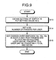
- the control unit 1 obtains information about number of fingers per user unit, which is set by the number-of-fingers setting switch 18 (step S13). Let us consider this value as b, which is internally set as the number of fingers (step S14).
- the change-over switches 14c, 15c, and 16c are set in such a way that a user unit (#1) uses the fingers 12-1 to 12-b, a user unit (#2) uses the fingers 12-b+1 to 12-2b, and so on (step S15). If the actual number of paths is less than the value b, some fingers are not used. If the value b is set too large, some fingers will not be utilized since it can not be possible to distribute the fingers to all the user units. However, on the contrary, by setting a high value for b, the number of fingers per user unit can be increased by reducing the number of user units.
- the number of input signals of rake combining units 13a to 13d of each user unit varies according to the setting of a change-over switch 16c.
- data are represented by bits of a fixed length. If the number of input signals varies, the optimum bit length after the combining process also varies accordingly. Consequently, according to the setting of the bit length, an overflow can occur after combining.
- a method of bit scaling is explained next as a countermeasure for the overflow of bit length.
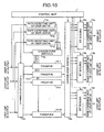
- Fig. 10 is an example a sixth embodiment, which is an embodiment of the present invention, wherein the configuration is the receiving apparatus shown in Fig. 3 with a bit scaling.
- the reference numerals 19a to 19d represent bit scaling units that trim, in accordance with the number of paths that are combined, the size of the demodulated signals carried by each finger.
- any overflow suppressing means can be used as long as it trims numerical values to prevent the overflow. For instance, means such as division by a certain number, an operation that extracts only some of the bits, subtraction, etc. can be employed.
- Bit scaling in the user unit (#1) is explained below.
- a bit scaling unit 19a that is placed between the change-over switch 16c and the rake combining unit 13a carries out the bit shift, based on the control of a control unit 1, to scale down each input level so as to avoid overflow after combining.
- the control unit 1 determines whether or not to carry out the bit scaling. For instance, when the number of demodulated signals to be combined exceeds the preset number, then bit scaling can be carried out in the corresponding bit scaling units 19a to 19d (however, if the number of demodulated signals to be combined does not exceed the preset number, bit scaling is not carried out). Alternatively, the value of the number of bits to be shifted k can be modified proportionate to the number of demodulated signals to be combined. Bit scaling can also be carried out when an occurrence of the overflow is detected.
- bit scaling is added to the structure corresponding to Fig. 3, it can be applied to the structure of other embodiments as well.
- control unit 1 sequentially and dynamically modifies allocation of fingers based on the communication status or the status of each user unit.
- a seventh embodiment explains below a configuration in which an already allocated finger is re-allocated to another user unit under certain special conditions.
- Fig. 11 is a block diagram of the demodulating apparatus according to the seventh embodiment. As shown in Fig. 11, the parts identical or equivalent to those shown in Fig. 4 are assigned the same reference numerals.
- a control unit 1 in the present embodiment monitors signal levels of demodulated signals of fingers 12-1 to 12-32. When the communication condition changes to a certain condition, the control unit 1 executes re-allocation of the fingers.
- the control unit 1 starts monitoring the demodulated signals of the fingers 12-1 to 12-32.
- the control unit 1 detects the demodulated signals of the fingers 12-1 to 12-32 (step S16) and then decides whether the signal levels of the detected demodulated signals are less than a preset value (default value) (step S17). If the signal level is too low, it means a signal is ineffectual even if the signal is combined with the other signals in rake combining units 13a to 13d. Therefore, such a signal level is taken as the default value, and when a value of signal level is out of the default value, the finger is to be re-allocated.
- step S16 If all the signal levels are higher than the default value, then the process returns to step S16, and starts over from detecting the demodulated signal levels after a certain time interval. If, on the other hand, the signal levels are lower than the default value, then it is determined whether the number of fingers allocated to the corresponding user unit is more than a predetermined number (defined number) (step S18). If the number of fingers allocated is not more than the defined number, the process returns to step S16. On the other hand, if the number of fingers allocated is more than the defined number, those excessive fingers are re-allocated to other user units (step S19). The user units to which the fingers are to be re-allocated are determined based on the methods explained in the first to sixth embodiments or based on an eighth embodiment explained next.
- An eighth embodiment explains below a configuration in which the number of fingers allocated to each user unit is modified based on levels of output signals from rake combining units 13a to 13d.
- Fig. 13 is a block diagram that explains the demodulating apparatus according to the eighth embodiment. As shown in Fig. 13, the parts identical or equivalent to those shown in Fig. 4 are assigned the same reference numerals.
- a control unit 1 is built in such a way that it detects output signals of each of the rake combining units 13a to 13d.
- the control unit 1 detects the output signals of each of the rake combining units 13a to 13d and then, based on signal levels of the output signals (i.e., signal intensities), determines number of fingers to be allocated to each user unit. For instance, for the rake combining units 13a to 13d having weak signal intensity, more number of fingers 12-1 to 12-32 is allocated.
- the rake combining units 13a to 13d having strong signal intensity less number of fingers 12-1 to 12-32 (less than the number of fingers allocated to the rake combining units 13a to 13d having weak signal intensity) is allocated. According to this structure, it is possible not only to properly demodulate the weaker signals, but also to achieve a demodulating apparatus that can perform even in more stringent communication environments.
- the allocation method of at this moment can be a conventional method where a fixed number of fingers is predetermined or any of the methods explained in the first to sixth embodiments.
- the dynamic allocation of fingers to each user is explained in the first to eighth embodiments. These embodiments can be applied not only to the case that each user has only one channel, but also to the case that each user has signals of a plurality of channels.
- the user units that are allocated to each user can be allocated to each channel, and if the path detecting units 11a to 11d detect paths of corresponding channels, it is possible to dynamically allocate the fingers as explained above.
- the receiving apparatus explained in the first to eighth embodiments can also be applied to a terminal apparatus.
- the terminal apparatus performs communications using a plurality of base transceiver stations or a plurality of channels
- the path detecting units 11a to 11d can detect corresponding paths for each channel, and it is possible to dynamically allocate fingers.
- control unit 1 can dynamically modify the number of allocations in accordance with the changes in communication conditions even when the communication is in progress.
- This dynamic modification of finger allocation is carried out by the control unit 1 of the first to eighth embodiments by monitoring the change in the communication conditions and accordingly dynamically re-allocating a finger or fingers once allocated to one channel (or one user unit) to another channel. Consequently, communications of a better quality can be achieved owing to this finger allocation in response to the change in the communication conditions, such as communication environments etc.
- the multi-user demodulating apparatus, the receiving apparatus, and the multi-channel demodulating method according to the present invention are suitable for a communication apparatus that uses a plurality of demodulating units such as fingers for a plurality of reception signals.
Landscapes
- Engineering & Computer Science (AREA)
- Computer Networks & Wireless Communication (AREA)
- Signal Processing (AREA)
- Radio Transmission System (AREA)
- Mobile Radio Communication Systems (AREA)
- Circuits Of Receivers In General (AREA)
- Traffic Control Systems (AREA)
Claims (1)
- Empfangsvorrichtung, welche aufweist:mehrere Finger (12-1 - 12-16), die Pfade eines Empfangssignals aus mehreren Empfangssignalen getrennt demodulieren;eine Steuereinheit (1), die bestimmt, ob einer von einer Gruppe der Finger und alle Finger Pfade eines ersten Empfangssignals oder Pfade eines zweiten Empfangssignals demodulieren;eine erste Rechenkombinationseinheit (13a), die auf der Grundlage der Zuweisung von Fingern durch die Steuereinheit die von den Fingern ausgegebenen Demodulationssignale entsprechend dem ersten Empfangssignal rechenmäßig kombinieren; undeine zweite Rechenkombinationseinheit (13b), die auf der Grundlage der Zuweisung von Fingern durch die Steuereinheit die von den Fingern ausgegebenen demodulierten Signale entsprechend dem zweiten Empfangssignal rechenmäßig kombinieren, wobeidie erste Rechenkombinationseinheit eine Überlaufunterdrückungseinheit (19a) enthält, die einen Additionsüberlauf unterdrückt, wenn die demodulierten Signale von den Fingern auf der Grundlage der Anzahl der durch die Steuereinheit zugeteilten Finger kombiniert werden.
Applications Claiming Priority (3)
| Application Number | Priority Date | Filing Date | Title |
|---|---|---|---|
| JP2001103348A JP3468224B2 (ja) | 2001-04-02 | 2001-04-02 | マルチユーザ復調装置、受信装置、並びにマルチチャネル復調方法。 |
| JP2001103348 | 2001-04-02 | ||
| EP02707283A EP1376887A4 (de) | 2001-04-02 | 2002-04-01 | Mehrbenutzer-demodulationsvorrichtung, empfangsvorrichtung und mehrkanal-demodulationsverfahren |
Related Parent Applications (1)
| Application Number | Title | Priority Date | Filing Date |
|---|---|---|---|
| EP02707283A Division EP1376887A4 (de) | 2001-04-02 | 2002-04-01 | Mehrbenutzer-demodulationsvorrichtung, empfangsvorrichtung und mehrkanal-demodulationsverfahren |
Publications (2)
| Publication Number | Publication Date |
|---|---|
| EP1585228A1 EP1585228A1 (de) | 2005-10-12 |
| EP1585228B1 true EP1585228B1 (de) | 2006-11-29 |
Family
ID=18956419
Family Applications (3)
| Application Number | Title | Priority Date | Filing Date |
|---|---|---|---|
| EP02707283A Withdrawn EP1376887A4 (de) | 2001-04-02 | 2002-04-01 | Mehrbenutzer-demodulationsvorrichtung, empfangsvorrichtung und mehrkanal-demodulationsverfahren |
| EP20050012392 Expired - Lifetime EP1575182B1 (de) | 2001-04-02 | 2002-04-01 | Mehrbenutzer-Demodulationsvorrichtung, Empfangsvorrichtung und Mehrkanal-Demodulationsverfahren |
| EP20050012393 Expired - Lifetime EP1585228B1 (de) | 2001-04-02 | 2002-04-01 | Mehrbenutzer-demodulationsvorrichtung, empfangsvorrichtung und mehrkanal-demodulationsverfahren |
Family Applications Before (2)
| Application Number | Title | Priority Date | Filing Date |
|---|---|---|---|
| EP02707283A Withdrawn EP1376887A4 (de) | 2001-04-02 | 2002-04-01 | Mehrbenutzer-demodulationsvorrichtung, empfangsvorrichtung und mehrkanal-demodulationsverfahren |
| EP20050012392 Expired - Lifetime EP1575182B1 (de) | 2001-04-02 | 2002-04-01 | Mehrbenutzer-Demodulationsvorrichtung, Empfangsvorrichtung und Mehrkanal-Demodulationsverfahren |
Country Status (6)
| Country | Link |
|---|---|
| US (1) | US20040121754A1 (de) |
| EP (3) | EP1376887A4 (de) |
| JP (1) | JP3468224B2 (de) |
| CN (1) | CN1500316A (de) |
| DE (2) | DE60215869T2 (de) |
| WO (1) | WO2002082680A1 (de) |
Families Citing this family (7)
| Publication number | Priority date | Publication date | Assignee | Title |
|---|---|---|---|---|
| US7675963B2 (en) * | 2002-07-29 | 2010-03-09 | Infineon Technologies Ag | Method and device for passing parameters to rake receiver |
| US7221665B1 (en) * | 2003-06-09 | 2007-05-22 | Mower Vaughn L | System and method for PN encoded signal prioritization and collision mitigation |
| WO2005076492A1 (ja) * | 2004-02-03 | 2005-08-18 | Matsushita Electric Industrial Co., Ltd. | Rake受信装置およびrake受信方法 |
| US7586974B2 (en) | 2004-10-19 | 2009-09-08 | Telefonaktiebolaget L M Ericsson (Publ) | Method and apparatus for rake finger allocation in a DS-CDMA receiver |
| US7372895B2 (en) | 2004-12-08 | 2008-05-13 | Telefonaktiebolaget Lm Ericsson (Publ) | Method of and system for delay estimation with minimized finger allocation |
| US7480356B2 (en) | 2004-12-08 | 2009-01-20 | Telefonaktiebolaget L M Ericsson (Publ) | Method of and system for path selection in rich multipath conditions |
| US8345803B2 (en) * | 2008-10-02 | 2013-01-01 | Qualcomm Incorporated | Optimized finger assignment for improved multicarrier throughput |
Family Cites Families (14)
| Publication number | Priority date | Publication date | Assignee | Title |
|---|---|---|---|---|
| ZA938324B (en) * | 1992-11-24 | 1994-06-07 | Qualcomm Inc | Pilot carrier dot product circuit |
| FI932605A7 (fi) * | 1993-06-07 | 1994-12-08 | Nokia Telecommunications Oy | Tukiasemavastaanotinlaitteisto |
| US5608722A (en) * | 1995-04-03 | 1997-03-04 | Qualcomm Incorporated | Multi-user communication system architecture with distributed receivers |
| FI105430B (fi) * | 1995-05-24 | 2000-08-15 | Nokia Networks Oy | Tukiasemalaitteisto sekä menetelmä antennikeilan suuntaamiseksi |
| US5764687A (en) * | 1995-06-20 | 1998-06-09 | Qualcomm Incorporated | Mobile demodulator architecture for a spread spectrum multiple access communication system |
| JP3286189B2 (ja) * | 1996-11-14 | 2002-05-27 | 松下電器産業株式会社 | アルゴリズムダイバーシチを用いた受信装置 |
| US6055230A (en) * | 1997-09-05 | 2000-04-25 | Metawave Communications Corporation | Embedded digital beam switching |
| WO2000013334A1 (en) * | 1998-08-28 | 2000-03-09 | Siemens Aktiengesellschaft | Receiver and method of recovering data from radio signals |
| JP2000232430A (ja) * | 1999-02-08 | 2000-08-22 | Nec Corp | Rake(熊手)受信機 |
| JP2000252871A (ja) * | 1999-03-01 | 2000-09-14 | Sony Corp | 受信方法及び受信装置 |
| JP2001189680A (ja) | 1999-12-28 | 2001-07-10 | Hitachi Kokusai Electric Inc | 逆拡散装置 |
| EP1158688A1 (de) * | 2000-05-25 | 2001-11-28 | Lucent Technologies Inc. | Dynamische Fingerzuweisung für Rake-Empfänger |
| JP2002009663A (ja) * | 2000-06-21 | 2002-01-11 | Nec Corp | スペクトラム拡散通信用受信機 |
| US7031373B1 (en) * | 2000-08-15 | 2006-04-18 | Motorola, Inc. | Apparatus for controlling a plurality of receiver fingers in a CDMA receiver |
-
2001
- 2001-04-02 JP JP2001103348A patent/JP3468224B2/ja not_active Expired - Fee Related
-
2002
- 2002-04-01 EP EP02707283A patent/EP1376887A4/de not_active Withdrawn
- 2002-04-01 EP EP20050012392 patent/EP1575182B1/de not_active Expired - Lifetime
- 2002-04-01 DE DE2002615869 patent/DE60215869T2/de not_active Expired - Fee Related
- 2002-04-01 CN CNA028077903A patent/CN1500316A/zh active Pending
- 2002-04-01 DE DE2002616528 patent/DE60216528T2/de not_active Expired - Fee Related
- 2002-04-01 EP EP20050012393 patent/EP1585228B1/de not_active Expired - Lifetime
- 2002-04-01 WO PCT/JP2002/003265 patent/WO2002082680A1/ja not_active Ceased
- 2002-04-01 US US10/473,820 patent/US20040121754A1/en not_active Abandoned
Also Published As
| Publication number | Publication date |
|---|---|
| JP2002300087A (ja) | 2002-10-11 |
| DE60216528T2 (de) | 2007-09-27 |
| EP1376887A1 (de) | 2004-01-02 |
| DE60215869D1 (de) | 2006-12-14 |
| EP1585228A1 (de) | 2005-10-12 |
| JP3468224B2 (ja) | 2003-11-17 |
| EP1376887A4 (de) | 2004-11-17 |
| US20040121754A1 (en) | 2004-06-24 |
| EP1575182A3 (de) | 2005-10-05 |
| EP1575182A2 (de) | 2005-09-14 |
| DE60216528D1 (de) | 2007-01-11 |
| EP1575182B1 (de) | 2006-11-02 |
| CN1500316A (zh) | 2004-05-26 |
| WO2002082680A1 (en) | 2002-10-17 |
| DE60215869T2 (de) | 2007-05-31 |
Similar Documents
| Publication | Publication Date | Title |
|---|---|---|
| CN1094022C (zh) | 功率控制和业务信道解码的分时锁定指示指令电路和方法 | |
| CN1064494C (zh) | 组合了扩频信号所有可用多径组件的瑞克接收机 | |
| CA2224934A1 (en) | Rake receiver architecture for a mobile demodulator used in a cdma communication system | |
| US6993344B2 (en) | CDMA wireless base station | |
| EP1585228B1 (de) | Mehrbenutzer-demodulationsvorrichtung, empfangsvorrichtung und mehrkanal-demodulationsverfahren | |
| RU2174286C1 (ru) | Передатчик с коммутируемым временным разнесением при передаче для ограничения мощности передачи антенны и способ управления ею для базовой станции в системе связи с подвижными объектами | |
| JP2000232430A (ja) | Rake(熊手)受信機 | |
| WO2007147506A1 (en) | Method and apparatus for communication receiver despreading resource management | |
| US6704552B1 (en) | Mobile communication apparatus with an automatic frequency controller | |
| EP0641091B1 (de) | Vorrichtung mit entscheidungsgesteuerter Kanalschätzung in einer digitalen Mobilfunkverbindung | |
| US7050826B2 (en) | Hardware structure for a transmission/reception device for mobile radio applications, and method for processing data in such a transmission/reception device | |
| JP2000295200A (ja) | 干渉信号除去装置 | |
| EP1737139A2 (de) | Mehrkanalige gemeinsame Dekodierung in dem mobilen Handgerät | |
| US20030123529A1 (en) | Despreading method, spreading code assigning method, mobile terminal and base transceiver station | |
| US8149898B2 (en) | Mobile communication system receiver, path tracking method, and control program thereof | |
| EP1501203A1 (de) | Empfangsvorrichtung und empfangsverfahren | |
| CN102594397B (zh) | 一种多径信号处理方法及装置 | |
| EP1447919B1 (de) | Steuerverfahren zur Korrelatorenzuweisung in einem CDMA-Mobilkommunikationssystem | |
| EP2919403B1 (de) | Mehrpfadkombinationsverfahren, vorrichtung und mobilkommunikationssystem | |
| CN100452672C (zh) | 接收器 | |
| KR20040071779A (ko) | 원격 통신 시스템, 기지국, 모바일 단말기, 모바일단말기의 간섭 감소 방법 및 프로그램 제품 | |
| KR100395451B1 (ko) | 다중 사용자 간섭 제거 장치 및 방법 | |
| CN100508413C (zh) | Tdd-cdma电信系统中简化的实时信号处理的方法和设备 | |
| JP2003218738A (ja) | Cdma無線通信装置および方法 | |
| EP1364471B1 (de) | Multicode rake empfänger in einer mobilstation |
Legal Events
| Date | Code | Title | Description |
|---|---|---|---|
| PUAI | Public reference made under article 153(3) epc to a published international application that has entered the european phase |
Free format text: ORIGINAL CODE: 0009012 |
|
| AC | Divisional application: reference to earlier application |
Ref document number: 1376887 Country of ref document: EP Kind code of ref document: P |
|
| AK | Designated contracting states |
Kind code of ref document: A1 Designated state(s): DE FR GB |
|
| 17P | Request for examination filed |
Effective date: 20051104 |
|
| RAP1 | Party data changed (applicant data changed or rights of an application transferred) |
Owner name: MITSUBISHI DENKI KABUSHIKI KAISHA |
|
| AKX | Designation fees paid |
Designated state(s): DE FR GB |
|
| GRAP | Despatch of communication of intention to grant a patent |
Free format text: ORIGINAL CODE: EPIDOSNIGR1 |
|
| GRAS | Grant fee paid |
Free format text: ORIGINAL CODE: EPIDOSNIGR3 |
|
| GRAA | (expected) grant |
Free format text: ORIGINAL CODE: 0009210 |
|
| AC | Divisional application: reference to earlier application |
Ref document number: 1376887 Country of ref document: EP Kind code of ref document: P |
|
| AK | Designated contracting states |
Kind code of ref document: B1 Designated state(s): DE FR GB |
|
| REG | Reference to a national code |
Ref country code: GB Ref legal event code: FG4D |
|
| REF | Corresponds to: |
Ref document number: 60216528 Country of ref document: DE Date of ref document: 20070111 Kind code of ref document: P |
|
| PGFP | Annual fee paid to national office [announced via postgrant information from national office to epo] |
Ref country code: GB Payment date: 20070328 Year of fee payment: 6 |
|
| PGFP | Annual fee paid to national office [announced via postgrant information from national office to epo] |
Ref country code: DE Payment date: 20070430 Year of fee payment: 6 |
|
| ET | Fr: translation filed | ||
| PLBE | No opposition filed within time limit |
Free format text: ORIGINAL CODE: 0009261 |
|
| STAA | Information on the status of an ep patent application or granted ep patent |
Free format text: STATUS: NO OPPOSITION FILED WITHIN TIME LIMIT |
|
| 26N | No opposition filed |
Effective date: 20070830 |
|
| PGFP | Annual fee paid to national office [announced via postgrant information from national office to epo] |
Ref country code: FR Payment date: 20070314 Year of fee payment: 6 |
|
| GBPC | Gb: european patent ceased through non-payment of renewal fee |
Effective date: 20080401 |
|
| PG25 | Lapsed in a contracting state [announced via postgrant information from national office to epo] |
Ref country code: DE Free format text: LAPSE BECAUSE OF NON-PAYMENT OF DUE FEES Effective date: 20081101 |
|
| REG | Reference to a national code |
Ref country code: FR Ref legal event code: ST Effective date: 20081231 |
|
| PG25 | Lapsed in a contracting state [announced via postgrant information from national office to epo] |
Ref country code: FR Free format text: LAPSE BECAUSE OF NON-PAYMENT OF DUE FEES Effective date: 20080430 |
|
| PG25 | Lapsed in a contracting state [announced via postgrant information from national office to epo] |
Ref country code: GB Free format text: LAPSE BECAUSE OF NON-PAYMENT OF DUE FEES Effective date: 20080401 |