EP1585268A2 - Système de transfert des données avec circuit pour économiser de l'énergie - Google Patents
Système de transfert des données avec circuit pour économiser de l'énergie Download PDFInfo
- Publication number
- EP1585268A2 EP1585268A2 EP05009686A EP05009686A EP1585268A2 EP 1585268 A2 EP1585268 A2 EP 1585268A2 EP 05009686 A EP05009686 A EP 05009686A EP 05009686 A EP05009686 A EP 05009686A EP 1585268 A2 EP1585268 A2 EP 1585268A2
- Authority
- EP
- European Patent Office
- Prior art keywords
- component
- data transmission
- activation signal
- sleep
- base station
- Prior art date
- Legal status (The legal status is an assumption and is not a legal conclusion. Google has not performed a legal analysis and makes no representation as to the accuracy of the status listed.)
- Granted
Links
Images

Classifications
-
- G—PHYSICS
- G06—COMPUTING OR CALCULATING; COUNTING
- G06K—GRAPHICAL DATA READING; PRESENTATION OF DATA; RECORD CARRIERS; HANDLING RECORD CARRIERS
- G06K7/00—Methods or arrangements for sensing record carriers, e.g. for reading patterns
- G06K7/0008—General problems related to the reading of electronic memory record carriers, independent of its reading method, e.g. power transfer
-
- G—PHYSICS
- G07—CHECKING-DEVICES
- G07C—TIME OR ATTENDANCE REGISTERS; REGISTERING OR INDICATING THE WORKING OF MACHINES; GENERATING RANDOM NUMBERS; VOTING OR LOTTERY APPARATUS; ARRANGEMENTS, SYSTEMS OR APPARATUS FOR CHECKING NOT PROVIDED FOR ELSEWHERE
- G07C9/00—Individual registration on entry or exit
- G07C9/00174—Electronically operated locks; Circuits therefor; Nonmechanical keys therefor, e.g. passive or active electrical keys or other data carriers without mechanical keys
- G07C9/00309—Electronically operated locks; Circuits therefor; Nonmechanical keys therefor, e.g. passive or active electrical keys or other data carriers without mechanical keys operated with bidirectional data transmission between data carrier and locks
-
- G—PHYSICS
- G07—CHECKING-DEVICES
- G07C—TIME OR ATTENDANCE REGISTERS; REGISTERING OR INDICATING THE WORKING OF MACHINES; GENERATING RANDOM NUMBERS; VOTING OR LOTTERY APPARATUS; ARRANGEMENTS, SYSTEMS OR APPARATUS FOR CHECKING NOT PROVIDED FOR ELSEWHERE
- G07C9/00—Individual registration on entry or exit
- G07C9/20—Individual registration on entry or exit involving the use of a pass
- G07C9/28—Individual registration on entry or exit involving the use of a pass the pass enabling tracking or indicating presence
-
- H—ELECTRICITY
- H04—ELECTRIC COMMUNICATION TECHNIQUE
- H04L—TRANSMISSION OF DIGITAL INFORMATION, e.g. TELEGRAPHIC COMMUNICATION
- H04L12/00—Data switching networks
- H04L12/02—Details
- H04L12/12—Arrangements for remote connection or disconnection of substations or of equipment thereof
-
- H—ELECTRICITY
- H04—ELECTRIC COMMUNICATION TECHNIQUE
- H04W—WIRELESS COMMUNICATION NETWORKS
- H04W52/00—Power management, e.g. Transmission Power Control [TPC] or power classes
- H04W52/02—Power saving arrangements
- H04W52/0209—Power saving arrangements in terminal devices
- H04W52/0225—Power saving arrangements in terminal devices using monitoring of external events, e.g. the presence of a signal
- H04W52/0229—Power saving arrangements in terminal devices using monitoring of external events, e.g. the presence of a signal where the received signal is a wanted signal
-
- G—PHYSICS
- G07—CHECKING-DEVICES
- G07B—TICKET-ISSUING APPARATUS; FARE-REGISTERING APPARATUS; FRANKING APPARATUS
- G07B15/00—Arrangements or apparatus for collecting fares, tolls or entrance fees at one or more control points
- G07B15/06—Arrangements for road pricing or congestion charging of vehicles or vehicle users, e.g. automatic toll systems
- G07B15/063—Arrangements for road pricing or congestion charging of vehicles or vehicle users, e.g. automatic toll systems using wireless information transmission between the vehicle and a fixed station
-
- G—PHYSICS
- G07—CHECKING-DEVICES
- G07C—TIME OR ATTENDANCE REGISTERS; REGISTERING OR INDICATING THE WORKING OF MACHINES; GENERATING RANDOM NUMBERS; VOTING OR LOTTERY APPARATUS; ARRANGEMENTS, SYSTEMS OR APPARATUS FOR CHECKING NOT PROVIDED FOR ELSEWHERE
- G07C9/00—Individual registration on entry or exit
- G07C9/00174—Electronically operated locks; Circuits therefor; Nonmechanical keys therefor, e.g. passive or active electrical keys or other data carriers without mechanical keys
- G07C9/00309—Electronically operated locks; Circuits therefor; Nonmechanical keys therefor, e.g. passive or active electrical keys or other data carriers without mechanical keys operated with bidirectional data transmission between data carrier and locks
- G07C2009/00365—Electronically operated locks; Circuits therefor; Nonmechanical keys therefor, e.g. passive or active electrical keys or other data carriers without mechanical keys operated with bidirectional data transmission between data carrier and locks in combination with a wake-up circuit
-
- G—PHYSICS
- G07—CHECKING-DEVICES
- G07C—TIME OR ATTENDANCE REGISTERS; REGISTERING OR INDICATING THE WORKING OF MACHINES; GENERATING RANDOM NUMBERS; VOTING OR LOTTERY APPARATUS; ARRANGEMENTS, SYSTEMS OR APPARATUS FOR CHECKING NOT PROVIDED FOR ELSEWHERE
- G07C9/00—Individual registration on entry or exit
- G07C9/00174—Electronically operated locks; Circuits therefor; Nonmechanical keys therefor, e.g. passive or active electrical keys or other data carriers without mechanical keys
- G07C2009/00753—Electronically operated locks; Circuits therefor; Nonmechanical keys therefor, e.g. passive or active electrical keys or other data carriers without mechanical keys operated by active electrical keys
- G07C2009/00769—Electronically operated locks; Circuits therefor; Nonmechanical keys therefor, e.g. passive or active electrical keys or other data carriers without mechanical keys operated by active electrical keys with data transmission performed by wireless means
-
- Y—GENERAL TAGGING OF NEW TECHNOLOGICAL DEVELOPMENTS; GENERAL TAGGING OF CROSS-SECTIONAL TECHNOLOGIES SPANNING OVER SEVERAL SECTIONS OF THE IPC; TECHNICAL SUBJECTS COVERED BY FORMER USPC CROSS-REFERENCE ART COLLECTIONS [XRACs] AND DIGESTS
- Y02—TECHNOLOGIES OR APPLICATIONS FOR MITIGATION OR ADAPTATION AGAINST CLIMATE CHANGE
- Y02D—CLIMATE CHANGE MITIGATION TECHNOLOGIES IN INFORMATION AND COMMUNICATION TECHNOLOGIES [ICT], I.E. INFORMATION AND COMMUNICATION TECHNOLOGIES AIMING AT THE REDUCTION OF THEIR OWN ENERGY USE
- Y02D30/00—Reducing energy consumption in communication networks
- Y02D30/70—Reducing energy consumption in communication networks in wireless communication networks
Definitions
- the invention relates to a system with system components, between which a data transmission takes place, as well as a Method for controlling such a system in particular when recording the data transmission.
- a typical system of the type indicated is a cordless one Phone as it is for example in the essay "Cordless Telephone Sinus 11" in Lessons Jg. 45 4/1992, page 132 - 143 is explained.
- a cordless phone consists of two components, namely a base station and a battery-powered handset. These are each with a transmitter and a receiver for mutual communication equipped. If no phone call is made, Parts of both components become energy efficient Sleep mode switched. However, the recipients remain active, to be able to determine if from the other component a connection is required. The recipient held receiver of the handset limits its service life with one battery charge.
- These systems also contain two components, namely a base station and a transponder.
- the base station's identification of the transponder allows.
- the base station releases Opening a lock as soon as it is close identifies the transponder of an authorized person.
- the invention is based on the object, one with low Power consumption operating system with two system components, between which a data transmission takes place, to accomplish.
- a method for operating a be made available to such a system.
- the invention is based on the consideration that the specified Systems often only a very small fraction of theirs Total operating time make a data transfer.
- access control systems often only take a few seconds an identification or access control protocol per day worked off, namely, when a person actually Requires access.
- the invention enables the system in the remaining time with minimal energy consumption in Willingness to keep up and using both components (Base station and transponder) together in an active mode to switch, if only one of them a data transfer wishes - for example, because they are approaching a Person has determined. While this readiness can a possibly existing receiving device of a first Component remain switched off and a receiving device a second component needs only periodically activated for a short time, d. H.
- the invention also makes it possible for the transmission an activation signal or for data transmission greatly reduce the transmission power required and thus to achieve a further energy saving effect, since powerful Receiving equipment can be used without adversely affecting the energy consumption as they are turned on only for very short times.
- the signal transmissions between the system components preferably takes place wirelessly by electromagnetic waves, Light waves (for example, infrared light) or by means Ultrasonic.
- the embodiment according to claim 2 provides an access control system This is a particularly simple detection of whether a data transmission is desired allows.
- the desk Can manually or by the person requiring access be automatically operated.
- the embodiment according to claim 5 contributes to a low energy consumption, since the receiving device of first component is turned on only when this is necessary.
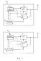
- the proximity sensing control system of FIG. 1 has a base station 1 and a transponder 2.
- the Base station 1 is suitable for replacing conventional mechanical Castles.
- the transponder 2 is mobile and prompted when approaching the base station 1 that this access Releases to a secured room, such as a door Electromagnetically opens.
- Base station 1 and transponder 2 are each with a Transmitter 3, 4 and a receiver 5, 6 provided. These are in turn connected to a respective protocol control 7, 8.
- the protocol controller 7 of the base station 1 communicates via the transmitter 3, 4 and via the receiver 5, 6 wirelessly with the protocol controller 8 of the transponder 2 to determine whether the transponder is assigned to an authorized person is.
- These are base station and transponder specific Data according to an identification or control protocol encrypted transfer.
- Base station 1 and transponder 2 are also each with a state control 9, 10 provided with the corresponding Transmitters 3, 4, receivers 5, 6 and protocol controls 7, 8 are connected to different operating states adjust.
- the majority of your operating time remains base station 1 and transponder 2 under the influence of the respective state control 9, 10 in an energy-efficient sleep mode.
- step 21 the state controller first causes all system devices (transmitter, receiver, protocol controller) of the enabling component to be turned off to put them into sleep mode. Only the state control itself remains switched on. Under its control, the activating system component remains in sleep mode for a certain waiting time T sleep, Tx (step 22).
- step 23 After expiration of the waiting period causes the state control a transition of the activating system component in one Detector mode (step 23).
- this mode will be short-lived a means of detecting if possibly a system component to be activated is located nearby, switched on.
- Sets the activating system component the Base station it can, for example by means of an infrared detector, a radar detector, an ultrasonic detector, a photocell; an induction loop or a microphone be determined whether a person or a Vehicle of the base station approaches carrying a transponder could, or a key is requested, which from the person approaching automatically or manually can be.
- step 24 in the event that none to be activated System component can be located nearby, back branches to step 21 to return to sleep mode.
- an activation signal is sent and on a response signal (acknowledgment) by the system component to be activated waited (step 26).
- step 27 branches back to step 21 to get the system component back into the To bring sleep mode.
- Upon receipt of a response signal i.e. if indeed a system component to be activated located nearby causes the state control in step 28, first the execution of the control protocol and then the return to sleep mode.
- step 31 The operation of the system component to be activated controlled by its state control is shown in FIG.
- all system devices except the associated state controller are turned off to put this system component in a sleep mode as well (step 31).
- the sleep mode is maintained for a waiting time T sleep.Rx (step 32).
- step 33 the system component is in the detector mode brought in which the receiver 5, 6 briefly turned on is to check if an activating system component sends an activation signal (step 33). Has been receive no activation signal, so branches step 34 back to step 31 and the system component returns to Sleep mode back.
- step 35 If an activation signal was received, then go put the system component into active mode, where all System devices (transmitters 3, 4 and protocol control 7, 8) are turned on (step 35). In active mode, first a response signal as an acknowledgment to the activating Component sent (step 36) and then with this the Processing of the control protocol started (step 37). To the processing of the control protocol will also be activated System component back to sleep mode.
- the energy consumption of the system is the lower the longer the waiting times T sleep.Tx and T sleep.Rx are selected. Too long waiting times, however, result in a noticeable delay between the approach of the transponder to the base station and the activation of the system.
- Favorable values are between 1/100 sec and 5 sec.
- the duration of the activation signal should exceed the waiting time T sleep.Rx by a small value so that the activation signal is reliably detected in step 33.
- the waiting times in the sleep mode are advantageously about 100 to 1000 times greater than the residence times in the detector mode.
- P Tx P sleep.Tx + P detect.Tx * T detect.Tx / T sleep.Tx
- P RX P sleep.RX + P detect.RX * T detect.RX / T sleep.RX .
- the mean power consumption of the system is therefore in the essential due to the low power consumption of the sleep mode and a very small fraction of the power consumption determined by the detector mode.
- the base station forms the activating and the transponder the system component to be activated.
- the Base station In detector mode, the Base station by means of a proximity sensor, whether approaching a person or a vehicle. If this is the case, then is activated by means of the activation signal and possibly Received response signal (acknowledgment) detects whether the Person or the vehicle also carry a transponder.
- the access authorization Verified During the processing of the control protocol then the access authorization Verified.
- this embodiment can also be modified so that the base station in the detector mode not (only) the approach of a person or a vehicle but directly recognizes the approach of a transponder. To It emits a sensor signal and evaluates the returned one Echoes off. Certain echoes are typical for transponders the present Art. If the sensor signal, for example from an electromagnetic pulse, so lets a transponder with nonlinear reflection behavior detect harmonics in the echo signal.
- a Transponder can be a ferromagnetic metal strip, the brought from the sensor signal in the range of saturation or tuned to resonate with the sensor signal High-frequency or radar resonant circuit, the one Diode with non-linear characteristic is added.
- the transition from the sleep mode to the detector mode is not automatically effected after a wait time T sleep.Tx but by manual operation of a switch or touch sensor .
- the switch or touch sensor is advantageously mounted in the door knob.
- the steps 22 and 23 of Fig. 2 are replaced by a step of detecting the key depression or the touch of a sensor.
- the base station forms the system component to be activated and the transponder the activating system component.
- the transponder By pressure on one Button, the transponder is caused to enter the sleep mode leave and an activation signal according to step 26 to the Base station to send.
- the two components of the system can also be the base station and represent the handset of a radiotelephone system, where both first as above for the to be activated System component described work. If a user however, if the handset starts a call, it will send Handset turns off the activation signal and takes on the role of activating system component. Conversely, the base station works sending the activation signal as activating System component as soon as it receives a telephone call, to be forwarded to the handset.
- the Steps 28 and 37 of FIGS. 2 and 3 are always through replaced the transmission of a telephone conversation.
- the steps 22, 23 and 24 of FIG. 2 are replaced by a step in which the activating component, if it is the base station represents a telephone call coming from the public network or, if it represents the handset, a keystroke determines with which the user the beginning of a telephone conversation displays.
Landscapes
- Engineering & Computer Science (AREA)
- Physics & Mathematics (AREA)
- General Physics & Mathematics (AREA)
- Computer Networks & Wireless Communication (AREA)
- Signal Processing (AREA)
- Artificial Intelligence (AREA)
- Computer Vision & Pattern Recognition (AREA)
- Theoretical Computer Science (AREA)
- Mobile Radio Communication Systems (AREA)
- Lock And Its Accessories (AREA)
- Small-Scale Networks (AREA)
Applications Claiming Priority (3)
| Application Number | Priority Date | Filing Date | Title |
|---|---|---|---|
| DE19519450A DE19519450C2 (de) | 1995-05-26 | 1995-05-26 | Kontrollsystem |
| DE19519450 | 1995-05-26 | ||
| EP96108471A EP0744843B1 (fr) | 1995-05-26 | 1996-05-28 | Système de communication de données |
Related Parent Applications (1)
| Application Number | Title | Priority Date | Filing Date |
|---|---|---|---|
| EP96108471.2 Division | 1996-05-28 |
Publications (3)
| Publication Number | Publication Date |
|---|---|
| EP1585268A2 true EP1585268A2 (fr) | 2005-10-12 |
| EP1585268A3 EP1585268A3 (fr) | 2012-08-01 |
| EP1585268B1 EP1585268B1 (fr) | 2013-08-14 |
Family
ID=7763003
Family Applications (2)
| Application Number | Title | Priority Date | Filing Date |
|---|---|---|---|
| EP96108471A Expired - Lifetime EP0744843B1 (fr) | 1995-05-26 | 1996-05-28 | Système de communication de données |
| EP05009686.6A Expired - Lifetime EP1585268B1 (fr) | 1995-05-26 | 1996-05-28 | Système de transfert des données avec circuit pour économiser de l'énergie |
Family Applications Before (1)
| Application Number | Title | Priority Date | Filing Date |
|---|---|---|---|
| EP96108471A Expired - Lifetime EP0744843B1 (fr) | 1995-05-26 | 1996-05-28 | Système de communication de données |
Country Status (2)
| Country | Link |
|---|---|
| EP (2) | EP0744843B1 (fr) |
| DE (2) | DE19519450C2 (fr) |
Cited By (10)
| Publication number | Priority date | Publication date | Assignee | Title |
|---|---|---|---|---|
| EP2026243A1 (fr) | 2007-03-19 | 2009-02-18 | SimonsVoss Technologies AG | Détection à faible énergie d'un transpondeur par une unité de lecture et système de constatation d'identité ou/et de constatation d'autorisation, le cas échéant sous forme de système de fermeture |
| WO2009149735A1 (fr) * | 2008-06-12 | 2009-12-17 | Siemens Aktiengesellschaft | Système et procédé de production et de réception d'un rayonnement électro-magnétique |
| WO2009140216A3 (fr) * | 2008-05-13 | 2010-01-07 | Qualcomm Incorporated | Charge de signalisation dans un environnement de puissance sans fil |
| WO2010052515A1 (fr) * | 2008-11-05 | 2010-05-14 | Telefonaktiebolaget Lm Ericsson (Publ) | Systèmes et procédés pour configurer un dispositif de démarcation |
| GB2487447A (en) * | 2011-01-10 | 2012-07-25 | Lear Corp | Combined personal convenience and remote fob device |
| US8854224B2 (en) | 2009-02-10 | 2014-10-07 | Qualcomm Incorporated | Conveying device information relating to wireless charging |
| US8878393B2 (en) | 2008-05-13 | 2014-11-04 | Qualcomm Incorporated | Wireless power transfer for vehicles |
| US9007195B2 (en) | 2004-06-25 | 2015-04-14 | Lear Corporation | Remote FOB integrated in a personal convenience device |
| US9312924B2 (en) | 2009-02-10 | 2016-04-12 | Qualcomm Incorporated | Systems and methods relating to multi-dimensional wireless charging |
| US9583953B2 (en) | 2009-02-10 | 2017-02-28 | Qualcomm Incorporated | Wireless power transfer for portable enclosures |
Families Citing this family (9)
| Publication number | Priority date | Publication date | Assignee | Title |
|---|---|---|---|---|
| WO2001023694A1 (fr) * | 1999-09-27 | 2001-04-05 | Tactel Ab | Systeme de verrouillage automatique |
| DE10302812B4 (de) | 2003-01-24 | 2006-10-05 | Hörmann KG Antriebstechnik | Überwachungsvorrichtung und Überwachungsverfahren für einen motorisch angetriebenen Gebäudeabschluss |
| DE10353466A1 (de) * | 2003-11-15 | 2005-06-23 | Aug. Winkhaus Gmbh & Co. Kg | Elektronisch aktivierbarer Sperrmechanismus |
| DE102004043212A1 (de) | 2004-09-03 | 2006-03-09 | Biotronik Vi Patent Ag | Kommunikationsmodul und Verfahren zu dessen Betrieb |
| KR100703215B1 (ko) * | 2006-02-20 | 2007-04-09 | 삼성전기주식회사 | 저전력 무선통신기기 및 저전력 무선통신 방법 |
| EP2469478A1 (fr) | 2010-12-21 | 2012-06-27 | 9Solutions Oy | Contrôle d'accès dans un système de suivi d'emplacement |
| DE202012009510U1 (de) * | 2012-10-04 | 2012-12-06 | Stefan Flache | Identifizierung von Katzen in mittlerer Entfernung. Vorrichtung zur eindeutigen Identifizierung von Katzen in mittleren Entfernungen (größer 10 Zentimeter bis wenige Meter) in Kombination mit einer Abstandbestimmung zum Zwecke der Ansteuerung einer elektronischen Katzenklappe |
| WO2019204954A1 (fr) * | 2018-04-23 | 2019-10-31 | 杭州全视软件有限公司 | Système de verrou intelligent |
| DE102021004067A1 (de) | 2021-08-06 | 2023-02-09 | Daimler Truck AG | Verfahren zur Überwachung einer Beleuchtungseinrichtung einer optischen Sensorvorrichtung, Steuervorrichtung zur Durchführung eines solchen Verfahrens, optische Sensorvorrichtung mit einer solchen Steuervorrichtung und Kraftfahrzeug mit einer solchen optischen Sensorvorrichtung |
Family Cites Families (7)
| Publication number | Priority date | Publication date | Assignee | Title |
|---|---|---|---|---|
| FR1531508A (fr) * | 1967-05-19 | 1968-07-05 | Système de tri automatique d'objets tels que sacs postaux | |
| US5299117A (en) * | 1990-01-02 | 1994-03-29 | Rest Manufacturing, Inc. | Power conserving receiver operation for a remote electronic display system |
| EP0502566A1 (fr) * | 1991-03-06 | 1992-09-09 | Delco Electronics Corporation | Appareil pour communiquer avec un véhicule |
| DE4111582C2 (de) * | 1991-04-10 | 1994-04-28 | Ifm Electronic Gmbh | Sende- und Empfangssystem, insbesondere für das Verriegeln und Entriegeln von Kraftfahrzeugtüren |
| US5339074A (en) * | 1991-09-13 | 1994-08-16 | Fluoroware, Inc. | Very low frequency tracking system |
| DE4134922C1 (fr) * | 1991-10-23 | 1992-12-03 | Anatoli 3013 Barsinghausen De Stobbe | |
| US5428820A (en) * | 1993-10-01 | 1995-06-27 | Motorola | Adaptive radio receiver controller method and apparatus |
-
1995
- 1995-05-26 DE DE19519450A patent/DE19519450C2/de not_active Expired - Lifetime
-
1996
- 1996-05-28 EP EP96108471A patent/EP0744843B1/fr not_active Expired - Lifetime
- 1996-05-28 EP EP05009686.6A patent/EP1585268B1/fr not_active Expired - Lifetime
- 1996-05-28 DE DE59611224T patent/DE59611224D1/de not_active Expired - Lifetime
Non-Patent Citations (1)
| Title |
|---|
| None |
Cited By (22)
| Publication number | Priority date | Publication date | Assignee | Title |
|---|---|---|---|---|
| US9007195B2 (en) | 2004-06-25 | 2015-04-14 | Lear Corporation | Remote FOB integrated in a personal convenience device |
| EP2026243A1 (fr) | 2007-03-19 | 2009-02-18 | SimonsVoss Technologies AG | Détection à faible énergie d'un transpondeur par une unité de lecture et système de constatation d'identité ou/et de constatation d'autorisation, le cas échéant sous forme de système de fermeture |
| US8892035B2 (en) | 2008-05-13 | 2014-11-18 | Qualcomm Incorporated | Repeaters for enhancement of wireless power transfer |
| US8965461B2 (en) | 2008-05-13 | 2015-02-24 | Qualcomm Incorporated | Reverse link signaling via receive antenna impedance modulation |
| US9991747B2 (en) | 2008-05-13 | 2018-06-05 | Qualcomm Incorporated | Signaling charging in wireless power environment |
| US8487478B2 (en) | 2008-05-13 | 2013-07-16 | Qualcomm Incorporated | Wireless power transfer for appliances and equipments |
| US8611815B2 (en) | 2008-05-13 | 2013-12-17 | Qualcomm Incorporated | Repeaters for enhancement of wireless power transfer |
| US8629650B2 (en) | 2008-05-13 | 2014-01-14 | Qualcomm Incorporated | Wireless power transfer using multiple transmit antennas |
| US9954399B2 (en) | 2008-05-13 | 2018-04-24 | Qualcomm Incorporated | Reverse link signaling via receive antenna impedance modulation |
| US8878393B2 (en) | 2008-05-13 | 2014-11-04 | Qualcomm Incorporated | Wireless power transfer for vehicles |
| WO2009140216A3 (fr) * | 2008-05-13 | 2010-01-07 | Qualcomm Incorporated | Charge de signalisation dans un environnement de puissance sans fil |
| US9236771B2 (en) | 2008-05-13 | 2016-01-12 | Qualcomm Incorporated | Method and apparatus for adaptive tuning of wireless power transfer |
| US9190875B2 (en) | 2008-05-13 | 2015-11-17 | Qualcomm Incorporated | Method and apparatus with negative resistance in wireless power transfers |
| US9130407B2 (en) | 2008-05-13 | 2015-09-08 | Qualcomm Incorporated | Signaling charging in wireless power environment |
| US9178387B2 (en) | 2008-05-13 | 2015-11-03 | Qualcomm Incorporated | Receive antenna for wireless power transfer |
| US9184632B2 (en) | 2008-05-13 | 2015-11-10 | Qualcomm Incorporated | Wireless power transfer for furnishings and building elements |
| WO2009149735A1 (fr) * | 2008-06-12 | 2009-12-17 | Siemens Aktiengesellschaft | Système et procédé de production et de réception d'un rayonnement électro-magnétique |
| WO2010052515A1 (fr) * | 2008-11-05 | 2010-05-14 | Telefonaktiebolaget Lm Ericsson (Publ) | Systèmes et procédés pour configurer un dispositif de démarcation |
| US9312924B2 (en) | 2009-02-10 | 2016-04-12 | Qualcomm Incorporated | Systems and methods relating to multi-dimensional wireless charging |
| US9583953B2 (en) | 2009-02-10 | 2017-02-28 | Qualcomm Incorporated | Wireless power transfer for portable enclosures |
| US8854224B2 (en) | 2009-02-10 | 2014-10-07 | Qualcomm Incorporated | Conveying device information relating to wireless charging |
| GB2487447A (en) * | 2011-01-10 | 2012-07-25 | Lear Corp | Combined personal convenience and remote fob device |
Also Published As
| Publication number | Publication date |
|---|---|
| DE19519450A1 (de) | 1996-11-28 |
| EP1585268B1 (fr) | 2013-08-14 |
| EP0744843B1 (fr) | 2005-05-04 |
| EP0744843A3 (fr) | 1999-11-17 |
| DE59611224D1 (de) | 2005-06-09 |
| EP1585268A3 (fr) | 2012-08-01 |
| DE19519450C2 (de) | 1997-06-12 |
| EP0744843A2 (fr) | 1996-11-27 |
Similar Documents
| Publication | Publication Date | Title |
|---|---|---|
| EP0744843B1 (fr) | Système de communication de données | |
| DE60131149T2 (de) | Passives Kommunikationsgerät und passives Zugangskontrollsystem | |
| DE102010001652B4 (de) | Automatische Erfassung des Entfernens von einem Fahrzeug | |
| DE102007062643B4 (de) | Elektronisches Schlüsselsystem und Verfahren | |
| DE102005056910B4 (de) | Integriertes System zum passiven Zugang und zum schlüssellosen Zugang per Fernsteuerung | |
| DE102009011471B4 (de) | Kommunikationssystem mit Synchronisation mehrerer Transceiver | |
| DE4329697C2 (de) | Fernsteuerbare Zugangskontrolleinrichtung | |
| DE102007020802B4 (de) | Fahrzeug-Steuersystem | |
| DE60121081T2 (de) | Sicherheitssystem zum Ermöglichen eines authentifizierten Zugangs einer Person zu einem gesichertem Raum | |
| DE102006016495A1 (de) | Energieeffizientes passives Schließsystem | |
| DE102014224999A1 (de) | Benutzernähedetektion zur Aktivierung von Fahrzeugkomfortfunktionen | |
| WO1999002377A1 (fr) | Dispositif de controle d'acces sans cle pour vehicules a moteur et procede pour realiser un controle d'autorisation d'acces sans cle dans un vehicule a moteur | |
| DE102017214109B4 (de) | Mobiler Identifikationsgeber | |
| DE102004013080B4 (de) | Fernsteuersystem für eine fahrzeuginterne Ausrüstung | |
| EP1447775A2 (fr) | Dispositif de verrouillage électronique | |
| DE102017203054B4 (de) | Zugangs- und Startsystem und Verfahren zur Zugangs- und Startverifizierung | |
| EP1041224A2 (fr) | Dispositif et procédé de libération d'un système de sécurité, en particulier d'un système d'accès pour véhicule automobile | |
| DE102005048411B4 (de) | Effiziente Energieüberwachungsstrategie für ein RKE-System | |
| DE102019211792B4 (de) | Zugangsanordnung für ein Fahrzeug | |
| EP1082712A2 (fr) | Systeme et procede de transmission de messages | |
| DE4330118C1 (de) | Fernsteuerbare Zugangskontrolleinrichtung, insbesondere für ein Kraftfahrzeug | |
| DE19832203A1 (de) | Verfahren zum Einschalten eines elektrisch betriebenen, stromverbrauchenden Bauelements sowie elektronische Schaltungsanordnung | |
| DE69404237T2 (de) | Alarmsystem für eine mobile Funkstation | |
| DE102004004257A1 (de) | Stromsparendes Wecken in Transponder-Schließsystemen | |
| DE19801124B4 (de) | System zum Datentransfer zwischen einem bewegten und einem festen Objekt |
Legal Events
| Date | Code | Title | Description |
|---|---|---|---|
| PUAI | Public reference made under article 153(3) epc to a published international application that has entered the european phase |
Free format text: ORIGINAL CODE: 0009012 |
|
| AC | Divisional application: reference to earlier application |
Ref document number: 0744843 Country of ref document: EP Kind code of ref document: P |
|
| AK | Designated contracting states |
Kind code of ref document: A2 Designated state(s): DE FR GB IT |
|
| RIN1 | Information on inventor provided before grant (corrected) |
Inventor name: SIMONS, OLIVER |
|
| PUAL | Search report despatched |
Free format text: ORIGINAL CODE: 0009013 |
|
| AK | Designated contracting states |
Kind code of ref document: A3 Designated state(s): DE FR GB IT |
|
| RIC1 | Information provided on ipc code assigned before grant |
Ipc: E05B 49/00 20060101ALI20120627BHEP Ipc: H04L 29/02 20060101ALI20120627BHEP Ipc: H04B 1/16 20060101ALI20120627BHEP Ipc: G07C 9/00 20060101ALI20120627BHEP Ipc: H04B 7/26 20060101AFI20120627BHEP |
|
| 17P | Request for examination filed |
Effective date: 20130111 |
|
| REG | Reference to a national code |
Ref country code: DE Ref legal event code: R079 Ref document number: 59611533 Country of ref document: DE Free format text: PREVIOUS MAIN CLASS: H04L0012400000 Ipc: H04B0007260000 |
|
| GRAP | Despatch of communication of intention to grant a patent |
Free format text: ORIGINAL CODE: EPIDOSNIGR1 |
|
| AKX | Designation fees paid |
Designated state(s): DE FR GB IT |
|
| RIC1 | Information provided on ipc code assigned before grant |
Ipc: E05B 49/00 20060101ALI20130307BHEP Ipc: H04B 1/16 20060101ALI20130307BHEP Ipc: H04B 7/26 20060101AFI20130307BHEP Ipc: H04L 29/02 20060101ALI20130307BHEP Ipc: G07C 9/00 20060101ALI20130307BHEP |
|
| GRAS | Grant fee paid |
Free format text: ORIGINAL CODE: EPIDOSNIGR3 |
|
| GRAP | Despatch of communication of intention to grant a patent |
Free format text: ORIGINAL CODE: EPIDOSNIGR1 |
|
| INTG | Intention to grant announced |
Effective date: 20130610 |
|
| GRAA | (expected) grant |
Free format text: ORIGINAL CODE: 0009210 |
|
| AC | Divisional application: reference to earlier application |
Ref document number: 0744843 Country of ref document: EP Kind code of ref document: P |
|
| AK | Designated contracting states |
Kind code of ref document: B1 Designated state(s): DE FR GB IT |
|
| REG | Reference to a national code |
Ref country code: GB Ref legal event code: FG4D Free format text: NOT ENGLISH |
|
| REG | Reference to a national code |
Ref country code: DE Ref legal event code: R096 Ref document number: 59611533 Country of ref document: DE Effective date: 20131010 |
|
| RAP2 | Party data changed (patent owner data changed or rights of a patent transferred) |
Owner name: SIMONSVOSS TECHNOLOGIES GMBH |
|
| REG | Reference to a national code |
Ref country code: DE Ref legal event code: R082 Ref document number: 59611533 Country of ref document: DE Representative=s name: VOSSIUS & PARTNER, DE Effective date: 20130919 Ref country code: DE Ref legal event code: R081 Ref document number: 59611533 Country of ref document: DE Owner name: SIMONSVOSS TECHNOLOGIES GMBH, DE Free format text: FORMER OWNER: SIMONSVOSS TECHNOLOGIES AG, 85774 UNTERFOEHRING, DE Effective date: 20130819 Ref country code: DE Ref legal event code: R081 Ref document number: 59611533 Country of ref document: DE Owner name: SIMONSVOSS TECHNOLOGIES GMBH, DE Free format text: FORMER OWNER: SIMONSVOSS TECHNOLOGIES AG, 85774 UNTERFOEHRING, DE Effective date: 20130919 Ref country code: DE Ref legal event code: R082 Ref document number: 59611533 Country of ref document: DE Representative=s name: VOSSIUS & PARTNER PATENTANWAELTE RECHTSANWAELT, DE Effective date: 20130919 |
|
| PG25 | Lapsed in a contracting state [announced via postgrant information from national office to epo] |
Ref country code: IT Free format text: LAPSE BECAUSE OF FAILURE TO SUBMIT A TRANSLATION OF THE DESCRIPTION OR TO PAY THE FEE WITHIN THE PRESCRIBED TIME-LIMIT Effective date: 20130814 |
|
| PLBE | No opposition filed within time limit |
Free format text: ORIGINAL CODE: 0009261 |
|
| STAA | Information on the status of an ep patent application or granted ep patent |
Free format text: STATUS: NO OPPOSITION FILED WITHIN TIME LIMIT |
|
| 26N | No opposition filed |
Effective date: 20140515 |
|
| REG | Reference to a national code |
Ref country code: DE Ref legal event code: R097 Ref document number: 59611533 Country of ref document: DE Effective date: 20140515 |
|
| GBPC | Gb: european patent ceased through non-payment of renewal fee |
Effective date: 20140528 |
|
| REG | Reference to a national code |
Ref country code: FR Ref legal event code: ST Effective date: 20150130 |
|
| PG25 | Lapsed in a contracting state [announced via postgrant information from national office to epo] |
Ref country code: GB Free format text: LAPSE BECAUSE OF NON-PAYMENT OF DUE FEES Effective date: 20140528 Ref country code: FR Free format text: LAPSE BECAUSE OF NON-PAYMENT OF DUE FEES Effective date: 20140602 |
|
| PGFP | Annual fee paid to national office [announced via postgrant information from national office to epo] |
Ref country code: DE Payment date: 20150629 Year of fee payment: 20 |
|
| REG | Reference to a national code |
Ref country code: DE Ref legal event code: R071 Ref document number: 59611533 Country of ref document: DE |