EP1585268B1 - Datenübertragungssystem mit energiesparender Schaltung - Google Patents
Datenübertragungssystem mit energiesparender Schaltung Download PDFInfo
- Publication number
- EP1585268B1 EP1585268B1 EP05009686.6A EP05009686A EP1585268B1 EP 1585268 B1 EP1585268 B1 EP 1585268B1 EP 05009686 A EP05009686 A EP 05009686A EP 1585268 B1 EP1585268 B1 EP 1585268B1
- Authority
- EP
- European Patent Office
- Prior art keywords
- component
- data transmission
- activation signal
- sleep
- base station
- Prior art date
- Legal status (The legal status is an assumption and is not a legal conclusion. Google has not performed a legal analysis and makes no representation as to the accuracy of the status listed.)
- Expired - Lifetime
Links
Images

Classifications
-
- G—PHYSICS
- G06—COMPUTING OR CALCULATING; COUNTING
- G06K—GRAPHICAL DATA READING; PRESENTATION OF DATA; RECORD CARRIERS; HANDLING RECORD CARRIERS
- G06K7/00—Methods or arrangements for sensing record carriers, e.g. for reading patterns
- G06K7/0008—General problems related to the reading of electronic memory record carriers, independent of its reading method, e.g. power transfer
-
- G—PHYSICS
- G07—CHECKING-DEVICES
- G07C—TIME OR ATTENDANCE REGISTERS; REGISTERING OR INDICATING THE WORKING OF MACHINES; GENERATING RANDOM NUMBERS; VOTING OR LOTTERY APPARATUS; ARRANGEMENTS, SYSTEMS OR APPARATUS FOR CHECKING NOT PROVIDED FOR ELSEWHERE
- G07C9/00—Individual registration on entry or exit
- G07C9/00174—Electronically operated locks; Circuits therefor; Nonmechanical keys therefor, e.g. passive or active electrical keys or other data carriers without mechanical keys
- G07C9/00309—Electronically operated locks; Circuits therefor; Nonmechanical keys therefor, e.g. passive or active electrical keys or other data carriers without mechanical keys operated with bidirectional data transmission between data carrier and locks
-
- G—PHYSICS
- G07—CHECKING-DEVICES
- G07C—TIME OR ATTENDANCE REGISTERS; REGISTERING OR INDICATING THE WORKING OF MACHINES; GENERATING RANDOM NUMBERS; VOTING OR LOTTERY APPARATUS; ARRANGEMENTS, SYSTEMS OR APPARATUS FOR CHECKING NOT PROVIDED FOR ELSEWHERE
- G07C9/00—Individual registration on entry or exit
- G07C9/20—Individual registration on entry or exit involving the use of a pass
- G07C9/28—Individual registration on entry or exit involving the use of a pass the pass enabling tracking or indicating presence
-
- H—ELECTRICITY
- H04—ELECTRIC COMMUNICATION TECHNIQUE
- H04L—TRANSMISSION OF DIGITAL INFORMATION, e.g. TELEGRAPHIC COMMUNICATION
- H04L12/00—Data switching networks
- H04L12/02—Details
- H04L12/12—Arrangements for remote connection or disconnection of substations or of equipment thereof
-
- H—ELECTRICITY
- H04—ELECTRIC COMMUNICATION TECHNIQUE
- H04W—WIRELESS COMMUNICATION NETWORKS
- H04W52/00—Power management, e.g. Transmission Power Control [TPC] or power classes
- H04W52/02—Power saving arrangements
- H04W52/0209—Power saving arrangements in terminal devices
- H04W52/0225—Power saving arrangements in terminal devices using monitoring of external events, e.g. the presence of a signal
- H04W52/0229—Power saving arrangements in terminal devices using monitoring of external events, e.g. the presence of a signal where the received signal is a wanted signal
-
- G—PHYSICS
- G07—CHECKING-DEVICES
- G07B—TICKET-ISSUING APPARATUS; FARE-REGISTERING APPARATUS; FRANKING APPARATUS
- G07B15/00—Arrangements or apparatus for collecting fares, tolls or entrance fees at one or more control points
- G07B15/06—Arrangements for road pricing or congestion charging of vehicles or vehicle users, e.g. automatic toll systems
- G07B15/063—Arrangements for road pricing or congestion charging of vehicles or vehicle users, e.g. automatic toll systems using wireless information transmission between the vehicle and a fixed station
-
- G—PHYSICS
- G07—CHECKING-DEVICES
- G07C—TIME OR ATTENDANCE REGISTERS; REGISTERING OR INDICATING THE WORKING OF MACHINES; GENERATING RANDOM NUMBERS; VOTING OR LOTTERY APPARATUS; ARRANGEMENTS, SYSTEMS OR APPARATUS FOR CHECKING NOT PROVIDED FOR ELSEWHERE
- G07C9/00—Individual registration on entry or exit
- G07C9/00174—Electronically operated locks; Circuits therefor; Nonmechanical keys therefor, e.g. passive or active electrical keys or other data carriers without mechanical keys
- G07C9/00309—Electronically operated locks; Circuits therefor; Nonmechanical keys therefor, e.g. passive or active electrical keys or other data carriers without mechanical keys operated with bidirectional data transmission between data carrier and locks
- G07C2009/00365—Electronically operated locks; Circuits therefor; Nonmechanical keys therefor, e.g. passive or active electrical keys or other data carriers without mechanical keys operated with bidirectional data transmission between data carrier and locks in combination with a wake-up circuit
-
- G—PHYSICS
- G07—CHECKING-DEVICES
- G07C—TIME OR ATTENDANCE REGISTERS; REGISTERING OR INDICATING THE WORKING OF MACHINES; GENERATING RANDOM NUMBERS; VOTING OR LOTTERY APPARATUS; ARRANGEMENTS, SYSTEMS OR APPARATUS FOR CHECKING NOT PROVIDED FOR ELSEWHERE
- G07C9/00—Individual registration on entry or exit
- G07C9/00174—Electronically operated locks; Circuits therefor; Nonmechanical keys therefor, e.g. passive or active electrical keys or other data carriers without mechanical keys
- G07C2009/00753—Electronically operated locks; Circuits therefor; Nonmechanical keys therefor, e.g. passive or active electrical keys or other data carriers without mechanical keys operated by active electrical keys
- G07C2009/00769—Electronically operated locks; Circuits therefor; Nonmechanical keys therefor, e.g. passive or active electrical keys or other data carriers without mechanical keys operated by active electrical keys with data transmission performed by wireless means
-
- Y—GENERAL TAGGING OF NEW TECHNOLOGICAL DEVELOPMENTS; GENERAL TAGGING OF CROSS-SECTIONAL TECHNOLOGIES SPANNING OVER SEVERAL SECTIONS OF THE IPC; TECHNICAL SUBJECTS COVERED BY FORMER USPC CROSS-REFERENCE ART COLLECTIONS [XRACs] AND DIGESTS
- Y02—TECHNOLOGIES OR APPLICATIONS FOR MITIGATION OR ADAPTATION AGAINST CLIMATE CHANGE
- Y02D—CLIMATE CHANGE MITIGATION TECHNOLOGIES IN INFORMATION AND COMMUNICATION TECHNOLOGIES [ICT], I.E. INFORMATION AND COMMUNICATION TECHNOLOGIES AIMING AT THE REDUCTION OF THEIR OWN ENERGY USE
- Y02D30/00—Reducing energy consumption in communication networks
- Y02D30/70—Reducing energy consumption in communication networks in wireless communication networks
Definitions
- the invention relates to a system with system components, between which a data transmission takes place, and to a method for controlling such a system, in particular when recording the data transmission.
- a typical system of the type indicated is a cordless telephone as it is for example described in the article " Cordless Telephone Sinus 11 "in Lehrsclerosis Jg. 45 4/1992, page 132 - 143 is explained.
- a cordless phone consists of two components, namely a base station and a battery-powered handset. These are each equipped with a transmitter and a receiver for mutual communication. If no telephone call is made, parts of both components are switched to an energy-efficient sleep mode. However, the receivers remain active in order to be able to determine when a connection is required by the other component. The receiver of the handset that is ready to receive limits its operating time with one battery charge.
- These systems also include two components, namely a base station and a transponder.
- the base station triggers the opening of a lock as soon as it identifies the transponder of an authorized person nearby.
- the invention has for its object to provide a low power consuming system with two system components, between which a data transmission takes place.
- a method for operating such a system should be provided.
- the invention is based on the consideration that the specified systems often carry out a data transmission only during a very small fraction of their total operating time.
- an identification or access control protocol is often processed for only a few seconds per day, namely when a person actually requires access.
- the invention makes it possible to keep the system ready for the rest of the time with minimal energy consumption and with both components (Base station and transponder) together to switch to an active mode, even if only one of them wants a data transfer - for example, because it has detected the approach of a person.
- a possibly existing receiving device of a first component may remain switched off and a receiving device of a second component only needs to be activated periodically for a short time, ie switched on or set to full readiness for reception and may otherwise be switched off or remain in an energy-saving sleep mode without readiness to receive.
- This is energy efficient, since receiving devices usually have a relatively high power consumption in the activated mode.
- the power consumption is determined by the quiescent current in analog circuits, which are necessary to amplify relatively weak received signals. When the reception readiness is canceled, these analog circuits can be switched off, so that the quiescent current is very low.
- the invention furthermore makes it possible to greatly reduce the transmission powers necessary for the transmission of an activation signal or for the data transmission and thus to achieve a further energy-saving effect, since powerful reception devices can be used without adversely affecting the energy consumption, since they are only for very short times are turned on.
- the Signalüberträgept between the system components is preferably carried out wirelessly by electromagnetic waves, light waves (for example, infrared light) or by means of ultrasound.
- the embodiment according to claim 2 represents an access control system, which allows a particularly simple detection of whether data transmission is desired.
- the switch can be operated manually or automatically by the person requiring access.
- the embodiment according to claim 5 contributes to low energy consumption, since the receiving device of the first component is only turned on when necessary.
- the proximity-sensitive control system according to Fig. 1 has a base station 1 and a transponder 2.
- the base station 1 is suitable for replacing conventional mechanical locks.
- the transponder 2 is mobile and causes when approaching the base station 1, that this releases the access to a secure room, for example, a door opens electromagnetically.
- Base station 1 and transponder 2 are each provided with a transmitter 3, 4 and a receiver 5, 6. These are in turn connected to a respective protocol control 7, 8.
- the protocol controller 7 of the base station 1 communicates via the transmitter 3, 4 and via the receiver 5, 6 wirelessly with the protocol controller 8 of the transponder 2 to determine whether the transponder is assigned to an authorized person.
- base station and transponder-specific data are transmitted in encrypted form in accordance with an identification or control protocol.
- Base station 1 and transponder 2 are also each provided with a state controller 9, 10 which are connected to the respective transmitters 3, 4, receivers 5, 6 and protocol controllers 7, 8 to set various operating conditions.
- the majority of your operating time remain base station 1 and transponder 2 under the influence of the respective state control 9, 10 in an energy-efficient sleep mode.
- the transmitters 3, 4, the receivers 5, 6 and the protocol controls 7, 8 are switched off. Only the state controllers 9, 10 remain active.
- the state controllers 9, 10 are different from each other.
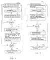
- that system component (base station 1 or transponder 2) which initiates the activation is referred to as “activating component” and the other system component (transponder 2 or base station 1) as “component to be activated”.
- step 21 the state controller first causes all system devices (transmitter, receiver, protocol controller) of the enabling component to be turned off to put them into sleep mode. Only the state control itself remains switched on. Under its control, the activating system component remains in sleep mode for a certain waiting time T sleep, Tx (step 22).
- the state controller After expiration of the waiting time, the state controller causes a transition of the activating system component in a detector mode (step 23).
- a means is briefly detected for detecting whether a system component to be activated is possibly located nearby, switched on. If the activating system component represents the base station, then, for example, by means of an infrared detector, a radar detector, an ultrasonic detector, a light barrier; an induction loop or a microphone are detected, whether a person or a vehicle approaches the base station, which could carry a transponder, or it is queried a button that can be operated automatically or manually by the approaching person.
- step 24 in the event that there is no system component to activate in the vicinity, it branches back to step 21 to return to sleep mode.
- Step 25 if there is a high probability that a system component to be activated in the vicinity, for example, because a person was detected nearby, all system devices, but in any case the corresponding transmitter 3, 4 and receiver 5, 6 are turned on and thus an active mode initiated ( Step 25).
- an activation signal is sent and waits for a response signal (acknowledgment) by the system component to be activated (step 26).
- step 27 branches back to step 21 to bring the system component back into sleep mode.
- the state control in step 28 Upon receipt of a response signal, i. If, in fact, a system component to be activated is in the vicinity, the state control in step 28 first causes the execution of the control protocol and then the return to the sleep mode.
- Fig. 3 The mode of operation of the system component to be activated controlled by its state control is in Fig. 3 shown. Thus, all system devices except the associated state controller are turned off to put this system component in a sleep mode as well (step 31). The sleep mode is maintained for a waiting time T sleep.Rx (step 32).
- step 33 the system component is brought into the detector mode in which the receiver 5, 6 is briefly turned on to check whether an activating system component sends an activation signal (step 33). If no activation signal has been received, then step 34 branches back to step 31 and the system component returns to sleep mode.
- the system component enters the active mode, in which all system devices (transmitters 3, 4 and protocol control 7, 8) are switched on (step 35).
- a response signal is first sent to the activating component as an acknowledgment (step 36) and then the protocol protocol is started (step 37).
- the system component to be activated also returns to sleep mode.
- the energy consumption of the system is the lower the longer the waiting times T sleep.Tx and T sleep.Rx are selected. Too long waiting times, however, result in a noticeable delay between the approach of the transponder to the base station and the activation of the system.
- Favorable values are between 1/100 sec and 5 sec.
- the duration of the activation signal should exceed the waiting time T sleep.Rx by a small value so that the activation signal is reliably detected in step 33.
- the waiting times in the sleep mode are advantageously about 100 to 1000 times greater than the residence times in the detector mode.
- the average power consumption of the system is thus essentially determined by the low power consumption of the sleep mode and a very small fraction of the power consumption of the detector mode.
- the base station forms the activating and the transponder the system component to be activated.
- the base station determines whether a person or a vehicle is approaching by means of a proximity sensor. If this is the case, it is detected by means of the activation signal and possibly received back response signal (acknowledgment), whether the person or the vehicle also carry a transponder.
- the access authorization is then verified.
- this embodiment can also be modified so that the base station detects in the detector mode not (only) the approach of a person or a vehicle but directly the approach of a transponder. For this purpose, it emits a sensor signal and evaluates the returned echoes. Certain echoes are typical for transponders of the present type.
- the sensor signal consists of an electromagnetic pulse
- a transponder with nonlinear reflection behavior can be detected by means of harmonics in the echo signal.
- the transponder may include a ferromagnetic metal strip brought into saturation by the sensor signal, or a high frequency or radar resonant circuit tuned approximately in resonance with the sensor signal, to which a non-linear characteristic diode is added.
- the transmitter 3, 4 and the receivers 5, 6 for transmitting the sensor signal and receiving the echo, which also serve to transmit the activation signal, the response signal and the data transmission according to the control protocol.
- the transition from the sleep mode to the detector mode is not automatically effected after a wait time T sleep.Tx but by manual operation of a switch or touch sensor .
- the switch or touch sensor is advantageously mounted in the door knob. Steps 22 and 23 off Fig. 2 are replaced by a step of detecting the button press or the touch of a sensor.
- the base station forms the system component to be activated and the transponder the activating system component. Pressing a key causes the transponder to exit sleep mode and send an activation signal to the base station according to step 26.
- the two components of the system may also represent the base station and handset of a radiotelephone system, both of which initially operate as described above for the system component to be activated.
- the handset sends out the activation signal and assumes the role of the activating system component.
- the base station operates to transmit the activation signal as an activating system component as soon as it receives a telephone call, which is to be forwarded to the handset.
- Steps 28 and 37 of FIGS. 2 and 3 are always replaced by the transmission of a telephone conversation.
- the steps 22, 23 and 24 of Fig. 2 are replaced by a step in which the activating component, when representing the base station, detects a telephone call coming from the exchange network or, if it represents the handset, determines a keystroke with which the user indicates the beginning of a telephone conversation.
Landscapes
- Engineering & Computer Science (AREA)
- Physics & Mathematics (AREA)
- General Physics & Mathematics (AREA)
- Computer Networks & Wireless Communication (AREA)
- Signal Processing (AREA)
- Artificial Intelligence (AREA)
- Computer Vision & Pattern Recognition (AREA)
- Theoretical Computer Science (AREA)
- Mobile Radio Communication Systems (AREA)
- Lock And Its Accessories (AREA)
- Small-Scale Networks (AREA)
Description
- Die Erfindung betrifft ein System mit Systemkomponenten, zwischen denen eine Datenübertragung stattfindet, sowie ein Verfahren zur Steuerung eines solchen Systems insbesondere bei der Aufnahme der Datenübertragung.
- Ein typisches System der angegebenen Art ist ein schnurloses Telefon wie es beispielsweise in dem Aufsatz "Schnurloses Telefon Sinus 11" in Unterrichtsblätter Jg. 45 4/1992, Seite 132 - 143 erläutert ist. Ein schnurloses Telefon besteht aus zwei Komponenten, nämlich einer Feststation und einem akkubetriebenen Handgerät. Diese sind jeweils mit einem Sender und einem Empfänger zur wechselseitigen Kommunikation ausgerüstet. Wenn kein Telefongespräch geführt wird, werden Teile beider Komponenten in einen energiesparenden Schlafmodus geschaltet. Die Empfänger verbleiben jedoch aktiv, um feststellen zu können, wenn von der anderen Komponente ein Verbindungsaufbau verlangt wird. Der empfangsbereit gehaltene Empfänger des Handgeräts begrenzt dessen Betriebsdauer mit einer Akkuladung.
- Andere Systeme der oben angegebenen Art sind annäherungssensitive Systeme zur automatischen drahtlosen Personen-und Fahrzeugidentifikation, beispielsweise im Rahmen von Verkehrsleitsystemen, bei der Mautgebührenerfassung oder bei der Zutrittskontrolle von Personen und Fahrzeugen zu gesicherten Räumen. Bei der Zutrittskontrolle können sie rein mechanische Schließsysteme ersetzen. Beispiele sind in
DE-A-41 11 582 ,DE-C-41 34 922 undDE-A-42 30 011 offenbart. - Auch diese Systeme beinhalten zwei Komponenten, nämlich eine Basisstation und einen Transponder.
- Zwischen beiden findet ein drahtloser Datenaustausch statt, der der Basisstation die Identifikation des Transponders ermöglicht. Bei der Zutrittskontrolle löst die Basisstation das Öffnen eines Schlosses aus, sobald sie in der Nähe den Transponder einer zutrittsberechtigten Person identifiziert.
- Konventionelle Systeme dieser Art sind mit folgenden Nachteilen behaftet. Idealerweise sollten sie annäherungssensitiv sein, d.h. sie sollten den Datenaustausch automatisch aufnehmen können, sobald sich der Transponder an die Basisstation annähert, ohne daß eine Bedienungsperson eingreifen muß. Dies erfordert, daß beide Komponenten stets eingeschaltet sind. Der Transponder hat oft nur die.Größe einer Kreditkarte oder eines Schlüsselanhängers, um leicht überall hin mitgeführt zu werden. Daher muß er mit winzigen Batterien betrieben werden, die im Dauerbetrieb nach kurzer Zeit erschöpft sind.
-
WO 9510141 US 5299117 sind erwähnbare Offenbarungen. - Zur Vermeidung dieses Nachteils werden passiv betriebene Transponder eingesetzt, die lediglich ein bestimmtes Echo eines von der Basisstation ausgesendeten Signals zurückwerfen oder es wurden Transponder vorgeschlagen, die ihre Betriebsenergie dem von der Basisstation ausgesendeten Signal entnehmen. Diese Systeme benötigen leistungsstarke Basisstationen, die entsprechend groß sind und einen hohen Stromverbrauch aufweisen. Außerdem sind sie wenig täuschungssicher.
- Der Erfindung liegt die Aufgabe zugrunde, ein mit geringem Leistungsverbrauch arbeitendes System mit zwei Systemkomponenten, zwischen denen eine Datenübertragung stattfindet, zu schaffen. Außerdem soll ein Verfahren zum Betrieb eines solchen Systems zur Verfügung gestellt werden.
- Die Lösung dieser Aufgabe gelingt mit dem in Anspruch 1 angegebenen Verfahren bzw. dem in Anspruch 6 angegebenen System.
- Die Erfindung beruht auf der Überlegung, daß die angegebenen Systeme häufig nur während eines sehr kleinen Bruchteils ihrer Gesamtbetriebszeit eine Datenübertragung vornehmen. Bei einem Zutrittskontrollsystem beispielsweise wird oft nur wenige Sekunden pro Tag ein Identifikations- bzw. Zutrittskontrollprotokoll abgearbeitet, nämlich dann, wenn eine Person tatsächlich Zutritt verlangt. Die Erfindung ermöglicht es, das System in der übrigen Zeit bei minimalem Energieverbrauch in Bereitschaft zu halten und mit beiden Komponenten (Basisstation und Transponder) gemeinsam in einen aktiven Modus zu wechseln, wenn auch nur eine von ihnen eine Datenübertragung wünscht - beispielsweise weil sie die Annäherung einer Person festgestellt hat. Während dieser Bereitschaft kann eine möglicherweise vorhandene Empfangseinrichtung einer ersten Komponente ausgeschaltet bleiben und eine Empfangseinrichtung einer zweiten Komponente braucht lediglich periodisch kurzzeitig aktiviert, d. h. eingeschaltet bzw. auf volle Empfangsbereitschaft gesetzt zu werden und kann sonst ausgeschaltet bzw. in einem energiesparenden Schlafmodus ohne Empfangsbereitschaft verbleiben. Dies ist energiesparend, da Empfangseinrichtungen gewöhnlich im aktivierten Betrieb einen relativ hohen Stromverbrauch aufweisen. Der Stromverbrauch ist durch den Ruhestrom in Analogschaltungen bestimmt, die zur Verstärkung relativ schwacher Empfangssignale notwendig sind. Bei aufgehobener Empfangsbereitschaft können diese Analogschaltungen abgeschaltet sein, so daß der Ruhestrom sehr gering ist.
- Die Erfindung ermöglicht es weiterhin, die für die Aussendung eines Aktivierungssignals oder für die Datenübertragung notwendigen Sendeleistungen stark zu reduzieren und somit einen weiteren Energiespareffekt zu erzielen, da leistungsfähige Empfangseinrichtungen verwendet werden können, ohne den Energieverbrauch nachteilig zu beeinflussen, da sie lediglich für sehr kurze Zeiten eingeschaltet sind.
- Die Signalüberträgungen zwischen den Systemkomponenten erfolgt vorzugsweise drahtlos durch elektromagnetische Wellen, Lichtwellen (beispielsweise Infrarotlicht) oder mittels Ultraschall.
- Die Unteransprüche betreffen vorteilhafte Ausgestaltungen der Erfindung.
- Die Ausgestaltung nach Anspruch 2 stellt ein Zutrittskontrollsystem dar, das eine besonders einfache Erkennung, ob eine Datenübertragung gewünscht ist, ermöglicht. Der Schalter kann von der einen Zutritt verlangenden Person manuell oder automatisch betätigt werden.
- Einen erhöhten Bedienungskomfort weist die Ausgestaltung nach Anspruch 3 auf, da sie eine berührungslose, annäherungssensitive Aktivierung des Systems ermöglicht. Die besondere Ausgestaltung nach Anspruch 4 führt zu einem verringerten Energieverbrauch bei der Feststellung, ob Bedarf an einer Datenübertragung besteht.
- Auch die Ausgestaltung nach Anspruch 5 trägt zu einem geringen Energieverbrauch bei, da die Empfangseinrichtung der ersten Komponente lediglich dann eingeschaltet wird, wenn dies notwendig ist.
- Bevorzugte Ausführungsbeispiele der Erfindung sind in den Zeichnungen dargestellt, in denen
-
Figur 1 schematisch ein annäherungssensitives Kontrollsystem, und -
Figuren 2 und 3 Ablaufschemata für den Betrieb eines solchen Systems darstellen. - Das annäherungssensitive Kontrollsystem nach
Fig. 1 weist eine Basisstation 1 sowie einen Transponder 2 auf. Die Basisstation 1 eignet sich zum Ersatz herkömmlicher mechanischer Schlösser. Der Transponder 2 ist mobil und veranlaßt bei Annäherung an die Basisstation 1, daß diese den Zutritt zu einem gesicherten Raum freigibt, beispielsweise eine Tür elektromagnetisch öffnet. - Basisstation 1 und Transponder 2 sind jeweils mit einem Sender 3, 4 und einem Empfänger 5, 6 versehen. Diese sind wiederum mit jeweils einer Protokollsteuerung 7, 8 verbunden. Die Protokollsteuerung 7 der Basisstation 1 kommuniziert über die Sender 3, 4 sowie über die Empfänger 5, 6 drahtlos mit der Protokollsteuerung 8 des Transponders 2, um festzustellen, ob der Transponder einer zutrittsberechtigten Person zugeordnet ist. Dazu werden basisstations- und transponderspezifische Daten nach einem Identifikations- bzw. Kontrollprotokoll verschlüsselt übertragen.
- Basisstation 1 und Transponder 2 sind außerdem jeweils mit einer Zustandssteuerung 9, 10 versehen, die mit den entsprechenden Sendern 3, 4, Empfängern 5, 6 und Protokollsteuerungen 7, 8 verbunden sind, um verschiedene Betriebszustände einzustellen.
- Den größten Teil Ihrer Betriebszeit verbleiben Basisstation 1 und Transponder 2 unter dem Einfluß der jeweiligen Zustandssteuerung 9, 10 in einem energiesparenden Schlafmodus. In diesem Schlafmodus sind die Sender 3, 4, die Empfänger 5, 6 und die Protokollsteuerungen 7, 8 ausgeschaltet. Lediglich die Zustandssteuerungen 9, 10 bleiben aktiv.
- Bei einer Annäherung des Transponders 2 an die Basisstation 1 kann nun entweder die Basisstation oder der Transponder die zur Abarbeitung des Kontrollprotokolls führende Aktivierung des Systems einleiten. Dementsprechend unterscheiden sich die Zustandssteuerungen 9, 10 voneinander. Im folgenden wird diejenige Systemkomponente (Basisstation 1 oder Transponder 2), die die Aktivierung einleitet, als "aktivierende Komponente" und die andere Systemkomponente (Transponder 2 oder Basisstation 1) als "zu aktivierende Komponente" bezeichnet.
- Die von der entsprechenden Zustandssteuerung gesteuerte Arbeitsweise der aktivierenden Komponente ist in
Fig. 2 dargestellt. - In Schritt 21 veranlaßt die Zustandssteuerung zunächst, daß alle Systemeinrichtungen (Sender, Empfänger, Protokollsteuerung) der aktivierenden Komponente ausgeschaltet sind, um diese in den Schlafmodus zu bringen. Lediglich die Zustandssteuerung selber bleibt eingeschaltet. Unter ihrer Kontrolle bleibt die aktivierende Systemkomponente für eine gewisse Wartezeit Tsleep,Tx im Schlafmodus (Schritt 22).
- Nach Ablauf der Wartezeit veranlaßt die Zustandssteuerung einen Übergang der aktivierenden Systemkomponente in einen Detektormodus (Schritt 23). In diesem Modus wird kurzzeitig eine Einrichtung zur Erkennung, ob sich möglicherweise eine zu aktivierende Systemkomponente in der Nähe befindet, eingeschaltet. Stellt die aktivierende Systemkomponente die Basisstation dar, so kann beispielsweise mittels eines Infrarot-Melders, eines Radar-Melders, eines Ultraschall-Melders, einer Lichtschranke; einer Induktionsschleife oder eines Mikrophons festgestellt werden, ob sich eine Person oder ein Fahrzeug der Basisstation nähert, die einen Transponder mitführen könnten, oder es wird eine Taste abgefragt, die von der sich nähernden Person automatisch oder manuell betätigt werden kann.
- In Schritt 24 wird für den Fall, daß sich keine zu aktivierende Systemkomponente in der Nähe befinden kann, zurück zu Schritt 21 verzweigt, um in den Schlafmodus zurückzukehren.
- Befindet sich jedoch mit hoher Wahrscheinlichkeit eine zu aktivierende Systemkomponente in der Nähe, da beispielsweise eine Person in der Nähe festgestellt wurde, so werden alle Systemeinrichtungen, jedenfalls jedoch der entsprechende Sender 3, 4 und Empfänger 5, 6 eingeschaltet und damit ein aktiver Modus eingeleitet (Schritt 25).
- Daraufhin wird ein Aktivierungssignal abgesandt und auf ein Antwortsignal (Quittierung) durch die zu aktivierende Systemkomponente gewartet (Schritt 26).
- Erfolgt keine Quittierung, so verzweigt Schritt 27 zurück zu Schritt 21, um die Systemkomponente zurück in den Schlafmodus zu bringen. Bei Empfang eines Antwortsignals, d.h. wenn sich tatsächlich eine zu aktivierende Systemkomponente in der Nähe befindet, veranlaßt die Zustandssteuerung in Schritt 28 zunächst das Abarbeiten des Kontrollprotokolls und dann die Rückkehr in den Schlafmodus.
- Die von ihrer Zustandssteuerung kontrollierte Arbeitsweise der zu aktivierenden Systemkomponente ist in
Fig. 3 dargestellt. Demnach werden alle Systemeinrichtungen außer der zugehörigen Zustandssteuerung ausgeschaltet, um auch diese Systemkomponente in einen Schlafmodus zu setzen (Schritt 31). Der Schlafmodus wird für eine Wartezeit Tsleep.Rx beibehalten (Schritt 32). - Anschließend wird die Systemkomponente in den Detektormodus gebracht, in dem der Empfänger 5, 6 kurzzeitig eingeschaltet wird, um zu prüfen, ob eine aktivierende Systemkomponente ein Aktivierungssignal sendet (Schritt 33). Wurde kein Aktivierungssignal empfangen, so verzweigt Schritt 34 zurück zu Schritt 31 und die Systemkomponente kehrt in den Schlafmodus zurück.
- Wurde jedoch ein Aktivierungssignal empfangen, so geht die Systemkomponente in den aktiven Modus über, in dem alle Systemeinrichtungen (Sender 3, 4 und Protokollsteuerung 7, 8) eingeschaltet sind (Schritt 35). Im aktiven Modus wird zunächst ein Antwortsignal als Quittierung an die aktivierende Komponente gesendet (Schritt 36) und sodann mit dieser das Abarbeiten des Kontrollprotokolls begonnen (Schritt 37). Nach dem Abarbeiten des Kontrollprotokolls kehrt auch die zu aktivierende Systemkomponente in den Schlafmodus zurück.
- Der Energieverbrauch des Systems ist um so geringer, je länger die Wartezeiten Tsleep.Tx und Tsleep.Rx gewählt werden. Bei zu langen Wartezeiten ergibt sich jedoch eine merkliche Verzögerung zwischen der Annäherung des Transponders an die Basisstation und der Aktivierung des Systems. Günstige Werte liegen zwischen 1/100 sec und 5 sec.
- Die Dauer des Aktivierungssignals soll die Wartezeit Tsleep.Rx um einen kleinen Wert überschreiten, damit das Aktivierungssignal in Schritt 33 sicher erkannt wird.
- Unter der Annahme, daß die Systemkomponenten in aller Regel vom Detektormodus unmittelbar in den Schlafmodus zurückkehren und der Energieverbrauch des aktiven Modus somit vernachlässigt werden kann, beträgt die mittlere Leistungsaufnahme der aktivierenden Systemkomponente:


- Die Wartezeiten im Schlafmodus sind vorteilhafterweise etwa 100 bis 1000 mal größer als die Verweildauern im Detektormodus. Damit gilt näherungsweise:


- Die mittlere Leistungsaufnahme des Systems ist also im wesentlichen durch die geringe Leistungsaufnahme des Schlafmodus und einen sehr kleinen Bruchteil der Leistungsaufnahme des Detektormodus bestimmt.
- In einem bereits angesprochenen Ausführungsbeispiel bildet die Basisstation die aktivierende und der Transponder die zu aktivierende Systemkomponente. Im Detektormodus stellt die Basisstation mittels eines Annäherungssensors fest, ob sich eine Person oder ein Fahrzeug nähert. Ist dies der Fall, so wird mittels des Aktivierungssignals und des möglicherweise zurückerhaltenen Antwortsignals (Quittierung) erkannt, ob die Person oder das Fahrzeug auch einen Transponder mitführen. Bei der Abarbeitung des Kontrollprotokolls wird dann die Zugangsberechtigung verifiziert.
- Vorteilhafterweise kann dieses Ausführungsbeispiel auch so abgeändert werden, daß die Basisstation im Detektormodus nicht (nur) die Annäherung einer Person oder eines Fahrzeugs sondern direkt die Annäherung eines Transponders erkennt. Dazu emittiert sie ein Sensor-Signal und wertet die zurückerhaltenen Echos aus. Bestimmte Echos sind typisch für Transponder der vorliegenden Art. Besteht das Sensor-Signal beispielsweise aus einem elektromagnetischen Impuls, so läßt sich ein Transponder mit nichtlinearem Reflexionsverhalten anhand von Oberwellen im Echosignal erkennen. Ein solcher Transponder kann einen ferromagnetischen Metallstreifen, der von dem Sensor-Signal in den Bereich der Sättigung gebracht wird, oder einen etwa auf Resonanz mit dem Sensor-Signal abgestimmten Hochfrequenz- oder Radar-Schwingkreis, dem eine Diode mit nichtlinearer Kennlinie hinzugefügt ist, aufweisen.
- Es ist ökonomisch, für das Aussenden des Sensor-Signals und den Empfang des Echos den Sender 3, 4 und den Empfänger 5, 6 zu verwenden, die auch der Übertragung des Aktivierungssignals, des Antwortsignals und der Datenübertragung nach dem Kontrollprotokoll dienen.
- Bei einem anderen Ausführungsbeispiel wird der Übergang vom Schlafmodus in den Detektormodus nicht automatisch nach einer Wartezeit Tsleep.Tx sondern durch manuelle Betätigung eines Schalters oder Berührungssensors bewirkt. Beim Einsatz in Wohnungstürschlössern ist der Schalter oder Berührungssensor vorteilhafterweise im Türknauf angebracht. Die Schritte 22 und 23 aus
Fig. 2 sind durch einen Schritt zur Erkennung des Tastendrucks oder der Berührung eines Sensors ersetzt. - Bei einem weiteren Ausführungsbeispiel bildet die Basisstation die zu aktivierende Systemkomponente und der Transponder die aktivierende Systemkomponente. Durch Druck auf eine Taste wird der Transponder veranlaßt, den Schlafmodus zu verlassen und ein Aktivierungssignal gemäß Schritt 26 an die Basisstation zu senden.
- Die beiden Komponenten des Systems können auch die Basisstation und das Handgerät eines Funktelefonsystems darstellen, wobei beide zunächst wie oben für die zu aktivierende Systemkomponente beschrieben arbeiten. Wenn ein Benutzer jedoch vom Handgerät einen Anruf beginnt, so sendet das Handgerät das Aktivierungssignal aus und nimmt die Rolle der aktivierenden Systemkomponente an. Umgekehrt arbeitet die Basisstation unter Aussenden des Aktivierungssignals als aktivierende Systemkomponente, sobald bei ihr ein Telefonruf eingeht, der an das Handgerät weitergeleitet werden soll. Die Schritte 28 und 37 der
Fig. 2 und 3 sind dabei stets durch die Übertragung eines Telefongesprächs ersetzt. Die Schritte 22, 23 und 24 derFig. 2 werden durch einen Schritt ersetzt, in dem die aktivierende Komponente, wenn sie die Basisstation darstellt, einen vom Amtsnetz eingehenden Telefonanruf feststellt oder, wenn sie das Handgerät darstellt, einen Tastendruck ermittelt, mit dem der Benutzer den Beginn eines Telefongesprächs anzeigt.
Claims (6)
- Verfahren zur Steuerung eines Systems bei der Aufnahme einer Datenübertragung zwischen einer ersten und einer zweiten Komponente (1, 2) des Systems, wobei die erste Komponente dann, wenn bei ihr Bedarf für die Datenübertragung vorliegt, ein Aktivierungssignal an die zweite Komponente sendet, um diese zur Aufnahme der Datenübertragung zu aktivieren,
wobei die erste Komponente eine Basisstation (1) und die zweite Komponente einen Transponder (2) eines Kontrollsystems darstellt, dadurch gekennzeichnet dass
die zweite Komponente wiederholt eine Empfangseinrichtung (5, 6) in Empfangsbereitschaft setzt, um ein Aussenden des Aktivierungssignals der ersten Komponente festzustellen, und dass sie dann, wenn sie dies nicht feststellen kann, die Empfangsbereitschaft für eine Wartezeit (Tsleep.Rx) wieder aufhebt, während sie sich bei Empfang des Aktivierungssignals für die Datenübertragung aktiviert,
wobei das Aktivierungssignal von der ersten Komponente für eine längere Zeitspanne als die genannte Wartezeit (Tsleep.Rx) ausgesandt wird. - Verfahren nach Anspruch 1, wobei die Datenübertragung die Abarbeitung eines Kontrollprotokolls zur Identifizierung einer der genannten Komponenten durch die andere beinhaltet und die erste Komponente die Betätigung eines Schalters oder Berührungssensors prüft, um festzustellen, ob Bedarf für die Datenübertragung vorliegt.
- Verfahren nach Anspruch 1, wobei die Datenübertragung die Abarbeitung eines Kontrollprotokolls zur Identifizierung einer der genannten Komponenten durch die andere beinhaltet und die erste Komponente das Ansprechen eines annäherungssensitiven Sensors, vorzugsweise eines Radarsensors oder Infrarotmelders prüft, um festzustellen, ob Bedarf für eine Datenübertragung besteht.
- Verfahren nach Anspruch 3, wobei das genannte Prüfen periodisch jeweils für kurze Zeit erfolgt.
- Verfahren nach einem der Ansprüche 1 bis 4, wobei die zweite Komponente bei Empfang des Aktivierungssignals ein Antwortsignal aussendet und die erste Komponente eine ihr zugeordnete Empfangseinrichtung (5, 6) in Empfangsbereitschaft setzt, um das Antwortsignal zu empfangen.
- System zur Aufnahme einer Datenübertragung zwischen einer ersten und einer zweiten Komponente (1, 2) des Systems,
wobei die erste Komponente eine Sendeeinrichtung (3, 4) aufweist, um dann, wenn bei ihr Bedarf für die Datenübertragung vorliegt, ein Aktivierungssignal an die zweite Komponente zu senden, und
wobei die zweite Komponente eine Empfangseinrichtung (5, 6) aufweist, um das Aktivierungssignal zu empfangen, woraufhin sie sich für die Datenübertragung aktiviert,
wobei die erste Komponente eine Basisstation (1) und die zweite Komponente einen Transponder (2) eines Kontrollsystems darstellt, dadurch gekennzeichnet dass
die zweite Komponente eine Steuereinrichtung (9, 10) aufweist, die die Empfangseinrichtung (5, 6) wiederholt in Empfangsbereitschaft setzt, um das Aussenden des Aktivierungssignals durch die erste Komponente festzustellen, und die dann, wenn kein Aktivierungssignal festgestellt werden konnte, die Empfangsbereitschaft für eine Wartezeit (TSleep.Rx) wieder aufhebt, während sie dann, wenn das Aktivierungssignal empfangen werden konnte, die zweite Komponente zur Datenübertragung aktiviert, und
die erste Komponente eine Einrichtung (9, 10) aufweist, um das genannte Aktivierungssignal für eine längere Zeitspanne als die genannte Wartezeit (Tsleep.Rx) auszusenden.
Applications Claiming Priority (3)
| Application Number | Priority Date | Filing Date | Title |
|---|---|---|---|
| DE19519450 | 1995-05-26 | ||
| DE19519450A DE19519450C2 (de) | 1995-05-26 | 1995-05-26 | Kontrollsystem |
| EP96108471A EP0744843B1 (de) | 1995-05-26 | 1996-05-28 | Datenübertragungssystem |
Related Parent Applications (1)
| Application Number | Title | Priority Date | Filing Date |
|---|---|---|---|
| EP96108471.2 Division | 1996-05-28 |
Publications (3)
| Publication Number | Publication Date |
|---|---|
| EP1585268A2 EP1585268A2 (de) | 2005-10-12 |
| EP1585268A3 EP1585268A3 (de) | 2012-08-01 |
| EP1585268B1 true EP1585268B1 (de) | 2013-08-14 |
Family
ID=7763003
Family Applications (2)
| Application Number | Title | Priority Date | Filing Date |
|---|---|---|---|
| EP96108471A Expired - Lifetime EP0744843B1 (de) | 1995-05-26 | 1996-05-28 | Datenübertragungssystem |
| EP05009686.6A Expired - Lifetime EP1585268B1 (de) | 1995-05-26 | 1996-05-28 | Datenübertragungssystem mit energiesparender Schaltung |
Family Applications Before (1)
| Application Number | Title | Priority Date | Filing Date |
|---|---|---|---|
| EP96108471A Expired - Lifetime EP0744843B1 (de) | 1995-05-26 | 1996-05-28 | Datenübertragungssystem |
Country Status (2)
| Country | Link |
|---|---|
| EP (2) | EP0744843B1 (de) |
| DE (2) | DE19519450C2 (de) |
Families Citing this family (19)
| Publication number | Priority date | Publication date | Assignee | Title |
|---|---|---|---|---|
| AU7697300A (en) * | 1999-09-27 | 2001-04-30 | Tactel Ab | Automatic locking system |
| DE10302812B4 (de) | 2003-01-24 | 2006-10-05 | Hörmann KG Antriebstechnik | Überwachungsvorrichtung und Überwachungsverfahren für einen motorisch angetriebenen Gebäudeabschluss |
| DE10353466A1 (de) * | 2003-11-15 | 2005-06-23 | Aug. Winkhaus Gmbh & Co. Kg | Elektronisch aktivierbarer Sperrmechanismus |
| US9007195B2 (en) | 2004-06-25 | 2015-04-14 | Lear Corporation | Remote FOB integrated in a personal convenience device |
| DE102004043212A1 (de) * | 2004-09-03 | 2006-03-09 | Biotronik Vi Patent Ag | Kommunikationsmodul und Verfahren zu dessen Betrieb |
| KR100703215B1 (ko) * | 2006-02-20 | 2007-04-09 | 삼성전기주식회사 | 저전력 무선통신기기 및 저전력 무선통신 방법 |
| ATE434795T1 (de) | 2007-03-19 | 2009-07-15 | Simonsvoss Technologies Ag | Lese-einheit und verfahren zur energiearmen detektion eines transponders |
| US8878393B2 (en) | 2008-05-13 | 2014-11-04 | Qualcomm Incorporated | Wireless power transfer for vehicles |
| US8629650B2 (en) | 2008-05-13 | 2014-01-14 | Qualcomm Incorporated | Wireless power transfer using multiple transmit antennas |
| WO2009149735A1 (de) * | 2008-06-12 | 2009-12-17 | Siemens Aktiengesellschaft | Anordnung und verfahren zum erzeugen und empfangen elektromagnetischer strahlung |
| WO2010052515A1 (en) * | 2008-11-05 | 2010-05-14 | Telefonaktiebolaget Lm Ericsson (Publ) | Systems and methods for configuring a demarcation device |
| US20100201312A1 (en) | 2009-02-10 | 2010-08-12 | Qualcomm Incorporated | Wireless power transfer for portable enclosures |
| US9312924B2 (en) | 2009-02-10 | 2016-04-12 | Qualcomm Incorporated | Systems and methods relating to multi-dimensional wireless charging |
| US8854224B2 (en) | 2009-02-10 | 2014-10-07 | Qualcomm Incorporated | Conveying device information relating to wireless charging |
| EP2469478A1 (de) * | 2010-12-21 | 2012-06-27 | 9Solutions Oy | Zugangssteuerung in einem Ortverfolgungssystem |
| GB2487447A (en) * | 2011-01-10 | 2012-07-25 | Lear Corp | Combined personal convenience and remote fob device |
| DE202012009510U1 (de) * | 2012-10-04 | 2012-12-06 | Stefan Flache | Identifizierung von Katzen in mittlerer Entfernung. Vorrichtung zur eindeutigen Identifizierung von Katzen in mittleren Entfernungen (größer 10 Zentimeter bis wenige Meter) in Kombination mit einer Abstandbestimmung zum Zwecke der Ansteuerung einer elektronischen Katzenklappe |
| WO2019204954A1 (zh) * | 2018-04-23 | 2019-10-31 | 杭州全视软件有限公司 | 一种智能锁系统 |
| DE102021004067A1 (de) | 2021-08-06 | 2023-02-09 | Daimler Truck AG | Verfahren zur Überwachung einer Beleuchtungseinrichtung einer optischen Sensorvorrichtung, Steuervorrichtung zur Durchführung eines solchen Verfahrens, optische Sensorvorrichtung mit einer solchen Steuervorrichtung und Kraftfahrzeug mit einer solchen optischen Sensorvorrichtung |
Family Cites Families (7)
| Publication number | Priority date | Publication date | Assignee | Title |
|---|---|---|---|---|
| FR1531508A (fr) * | 1967-05-19 | 1968-07-05 | Système de tri automatique d'objets tels que sacs postaux | |
| US5299117A (en) * | 1990-01-02 | 1994-03-29 | Rest Manufacturing, Inc. | Power conserving receiver operation for a remote electronic display system |
| EP0502566A1 (de) * | 1991-03-06 | 1992-09-09 | Delco Electronics Corporation | Gerät zur Kommunikation mit einem Fahrzeug |
| DE4111582C2 (de) * | 1991-04-10 | 1994-04-28 | Ifm Electronic Gmbh | Sende- und Empfangssystem, insbesondere für das Verriegeln und Entriegeln von Kraftfahrzeugtüren |
| US5339074A (en) * | 1991-09-13 | 1994-08-16 | Fluoroware, Inc. | Very low frequency tracking system |
| DE4134922C1 (de) * | 1991-10-23 | 1992-12-03 | Anatoli 3013 Barsinghausen De Stobbe | |
| US5428820A (en) * | 1993-10-01 | 1995-06-27 | Motorola | Adaptive radio receiver controller method and apparatus |
-
1995
- 1995-05-26 DE DE19519450A patent/DE19519450C2/de not_active Expired - Lifetime
-
1996
- 1996-05-28 EP EP96108471A patent/EP0744843B1/de not_active Expired - Lifetime
- 1996-05-28 DE DE59611224T patent/DE59611224D1/de not_active Expired - Lifetime
- 1996-05-28 EP EP05009686.6A patent/EP1585268B1/de not_active Expired - Lifetime
Also Published As
| Publication number | Publication date |
|---|---|
| EP0744843B1 (de) | 2005-05-04 |
| DE19519450C2 (de) | 1997-06-12 |
| DE19519450A1 (de) | 1996-11-28 |
| EP0744843A2 (de) | 1996-11-27 |
| EP0744843A3 (de) | 1999-11-17 |
| EP1585268A2 (de) | 2005-10-12 |
| EP1585268A3 (de) | 2012-08-01 |
| DE59611224D1 (de) | 2005-06-09 |
Similar Documents
| Publication | Publication Date | Title |
|---|---|---|
| EP1585268B1 (de) | Datenübertragungssystem mit energiesparender Schaltung | |
| DE102010001652B4 (de) | Automatische Erfassung des Entfernens von einem Fahrzeug | |
| DE102007020802B4 (de) | Fahrzeug-Steuersystem | |
| DE102006011032B4 (de) | Fahrzeugtür-Steuersystem | |
| DE102005056910B4 (de) | Integriertes System zum passiven Zugang und zum schlüssellosen Zugang per Fernsteuerung | |
| DE102006035651B4 (de) | Steuersystem für eine Fahrzeugausstattung und dazugehöriges Verfahren | |
| DE60226097T2 (de) | Passives Zugangssystem mit Antidiebstahlsfunktion | |
| DE102007062643B4 (de) | Elektronisches Schlüsselsystem und Verfahren | |
| DE102014224999A1 (de) | Benutzernähedetektion zur Aktivierung von Fahrzeugkomfortfunktionen | |
| DE102006016495A1 (de) | Energieeffizientes passives Schließsystem | |
| WO1999002377A1 (de) | Schlüssellose zugangskontrolleinrichtung für kraftfahrzeuge sowie verfahren zum durchführen einer schlüssellosen zugangsberechtigungskontrolle bei kraftfahrzeug | |
| DE102009011471A1 (de) | Kommunikationssystem mit Synchronisation mehrerer Transceiver | |
| DE102010021608A1 (de) | Verfahren zum passiven Detektieren einer Annäherung an ein Fahrzeug | |
| DE102006053964A1 (de) | Fahrzeugausstattungssteuersystem | |
| DE102015102006A1 (de) | Elektronisches Schlüsselsystem | |
| EP2817181A1 (de) | Passives zugangssystem für ein kraftfahrzeug und zugehöriges verfahren | |
| DE102004013080B4 (de) | Fernsteuersystem für eine fahrzeuginterne Ausrüstung | |
| DE102015204428A1 (de) | Steuergerät und Steuereinrichtung | |
| DE102017214109B4 (de) | Mobiler Identifikationsgeber | |
| DE102005048411B4 (de) | Effiziente Energieüberwachungsstrategie für ein RKE-System | |
| EP1447775A2 (de) | Elektronische Schliessvorrichtung | |
| DE102019211792B4 (de) | Zugangsanordnung für ein Fahrzeug | |
| EP1082712A2 (de) | Nachrichtenübertragung in einem funkbasierten system zur sicherung oder zugangskontrolle und methode dafür | |
| DE102017217978A1 (de) | Zugangssystem und Verfahren zur Zugangsverifizierung | |
| WO2000012845A1 (de) | Zugangs- und start/fahrberechtigungssystem für ein kraftfahrzeug |
Legal Events
| Date | Code | Title | Description |
|---|---|---|---|
| PUAI | Public reference made under article 153(3) epc to a published international application that has entered the european phase |
Free format text: ORIGINAL CODE: 0009012 |
|
| AC | Divisional application: reference to earlier application |
Ref document number: 0744843 Country of ref document: EP Kind code of ref document: P |
|
| AK | Designated contracting states |
Kind code of ref document: A2 Designated state(s): DE FR GB IT |
|
| RIN1 | Information on inventor provided before grant (corrected) |
Inventor name: SIMONS, OLIVER |
|
| PUAL | Search report despatched |
Free format text: ORIGINAL CODE: 0009013 |
|
| AK | Designated contracting states |
Kind code of ref document: A3 Designated state(s): DE FR GB IT |
|
| RIC1 | Information provided on ipc code assigned before grant |
Ipc: E05B 49/00 20060101ALI20120627BHEP Ipc: H04L 29/02 20060101ALI20120627BHEP Ipc: H04B 1/16 20060101ALI20120627BHEP Ipc: G07C 9/00 20060101ALI20120627BHEP Ipc: H04B 7/26 20060101AFI20120627BHEP |
|
| 17P | Request for examination filed |
Effective date: 20130111 |
|
| REG | Reference to a national code |
Ref country code: DE Ref legal event code: R079 Ref document number: 59611533 Country of ref document: DE Free format text: PREVIOUS MAIN CLASS: H04L0012400000 Ipc: H04B0007260000 |
|
| GRAP | Despatch of communication of intention to grant a patent |
Free format text: ORIGINAL CODE: EPIDOSNIGR1 |
|
| AKX | Designation fees paid |
Designated state(s): DE FR GB IT |
|
| RIC1 | Information provided on ipc code assigned before grant |
Ipc: E05B 49/00 20060101ALI20130307BHEP Ipc: H04B 1/16 20060101ALI20130307BHEP Ipc: H04B 7/26 20060101AFI20130307BHEP Ipc: H04L 29/02 20060101ALI20130307BHEP Ipc: G07C 9/00 20060101ALI20130307BHEP |
|
| GRAS | Grant fee paid |
Free format text: ORIGINAL CODE: EPIDOSNIGR3 |
|
| GRAP | Despatch of communication of intention to grant a patent |
Free format text: ORIGINAL CODE: EPIDOSNIGR1 |
|
| INTG | Intention to grant announced |
Effective date: 20130610 |
|
| GRAA | (expected) grant |
Free format text: ORIGINAL CODE: 0009210 |
|
| AC | Divisional application: reference to earlier application |
Ref document number: 0744843 Country of ref document: EP Kind code of ref document: P |
|
| AK | Designated contracting states |
Kind code of ref document: B1 Designated state(s): DE FR GB IT |
|
| REG | Reference to a national code |
Ref country code: GB Ref legal event code: FG4D Free format text: NOT ENGLISH |
|
| REG | Reference to a national code |
Ref country code: DE Ref legal event code: R096 Ref document number: 59611533 Country of ref document: DE Effective date: 20131010 |
|
| RAP2 | Party data changed (patent owner data changed or rights of a patent transferred) |
Owner name: SIMONSVOSS TECHNOLOGIES GMBH |
|
| REG | Reference to a national code |
Ref country code: DE Ref legal event code: R082 Ref document number: 59611533 Country of ref document: DE Representative=s name: VOSSIUS & PARTNER, DE Effective date: 20130919 Ref country code: DE Ref legal event code: R081 Ref document number: 59611533 Country of ref document: DE Owner name: SIMONSVOSS TECHNOLOGIES GMBH, DE Free format text: FORMER OWNER: SIMONSVOSS TECHNOLOGIES AG, 85774 UNTERFOEHRING, DE Effective date: 20130819 Ref country code: DE Ref legal event code: R081 Ref document number: 59611533 Country of ref document: DE Owner name: SIMONSVOSS TECHNOLOGIES GMBH, DE Free format text: FORMER OWNER: SIMONSVOSS TECHNOLOGIES AG, 85774 UNTERFOEHRING, DE Effective date: 20130919 Ref country code: DE Ref legal event code: R082 Ref document number: 59611533 Country of ref document: DE Representative=s name: VOSSIUS & PARTNER PATENTANWAELTE RECHTSANWAELT, DE Effective date: 20130919 |
|
| PG25 | Lapsed in a contracting state [announced via postgrant information from national office to epo] |
Ref country code: IT Free format text: LAPSE BECAUSE OF FAILURE TO SUBMIT A TRANSLATION OF THE DESCRIPTION OR TO PAY THE FEE WITHIN THE PRESCRIBED TIME-LIMIT Effective date: 20130814 |
|
| PLBE | No opposition filed within time limit |
Free format text: ORIGINAL CODE: 0009261 |
|
| STAA | Information on the status of an ep patent application or granted ep patent |
Free format text: STATUS: NO OPPOSITION FILED WITHIN TIME LIMIT |
|
| 26N | No opposition filed |
Effective date: 20140515 |
|
| REG | Reference to a national code |
Ref country code: DE Ref legal event code: R097 Ref document number: 59611533 Country of ref document: DE Effective date: 20140515 |
|
| GBPC | Gb: european patent ceased through non-payment of renewal fee |
Effective date: 20140528 |
|
| REG | Reference to a national code |
Ref country code: FR Ref legal event code: ST Effective date: 20150130 |
|
| PG25 | Lapsed in a contracting state [announced via postgrant information from national office to epo] |
Ref country code: GB Free format text: LAPSE BECAUSE OF NON-PAYMENT OF DUE FEES Effective date: 20140528 Ref country code: FR Free format text: LAPSE BECAUSE OF NON-PAYMENT OF DUE FEES Effective date: 20140602 |
|
| PGFP | Annual fee paid to national office [announced via postgrant information from national office to epo] |
Ref country code: DE Payment date: 20150629 Year of fee payment: 20 |
|
| REG | Reference to a national code |
Ref country code: DE Ref legal event code: R071 Ref document number: 59611533 Country of ref document: DE |