EP1585308A1 - Appareil pour lire des informations radiographiques d'un panneau luminescent d'enregistrement - Google Patents
Appareil pour lire des informations radiographiques d'un panneau luminescent d'enregistrement Download PDFInfo
- Publication number
- EP1585308A1 EP1585308A1 EP04101370A EP04101370A EP1585308A1 EP 1585308 A1 EP1585308 A1 EP 1585308A1 EP 04101370 A EP04101370 A EP 04101370A EP 04101370 A EP04101370 A EP 04101370A EP 1585308 A1 EP1585308 A1 EP 1585308A1
- Authority
- EP
- European Patent Office
- Prior art keywords
- carrier
- component
- bearing
- freedom
- read
- Prior art date
- Legal status (The legal status is an assumption and is not a legal conclusion. Google has not performed a legal analysis and makes no representation as to the accuracy of the status listed.)
- Granted
Links
- OAICVXFJPJFONN-UHFFFAOYSA-N Phosphorus Chemical compound [P] OAICVXFJPJFONN-UHFFFAOYSA-N 0.000 title claims description 27
- 238000003860 storage Methods 0.000 title description 5
- 230000005855 radiation Effects 0.000 claims abstract description 27
- 230000000638 stimulation Effects 0.000 claims description 14
- 238000005452 bending Methods 0.000 claims description 5
- 229920000049 Carbon (fiber) Polymers 0.000 claims description 2
- 239000004917 carbon fiber Substances 0.000 claims description 2
- 239000000835 fiber Substances 0.000 claims description 2
- 239000003365 glass fiber Substances 0.000 claims description 2
- 239000004033 plastic Substances 0.000 claims description 2
- 229920003023 plastic Polymers 0.000 claims description 2
- 239000002990 reinforced plastic Substances 0.000 claims description 2
- 230000001678 irradiating effect Effects 0.000 claims 1
- 238000004088 simulation Methods 0.000 abstract 1
- 239000010410 layer Substances 0.000 description 20
- 230000003287 optical effect Effects 0.000 description 8
- 230000035939 shock Effects 0.000 description 4
- 230000009286 beneficial effect Effects 0.000 description 2
- 239000000463 material Substances 0.000 description 2
- 239000012790 adhesive layer Substances 0.000 description 1
- 238000003491 array Methods 0.000 description 1
- 239000004918 carbon fiber reinforced polymer Substances 0.000 description 1
- 230000006735 deficit Effects 0.000 description 1
- 230000000694 effects Effects 0.000 description 1
- 238000011156 evaluation Methods 0.000 description 1
- 239000011152 fibreglass Substances 0.000 description 1
- 238000003780 insertion Methods 0.000 description 1
- 230000037431 insertion Effects 0.000 description 1
- 230000009191 jumping Effects 0.000 description 1
- 238000004519 manufacturing process Methods 0.000 description 1
- 238000000034 method Methods 0.000 description 1
- 238000005096 rolling process Methods 0.000 description 1
- 230000000087 stabilizing effect Effects 0.000 description 1
Images

Classifications
-
- H—ELECTRICITY
- H04—ELECTRIC COMMUNICATION TECHNIQUE
- H04N—PICTORIAL COMMUNICATION, e.g. TELEVISION
- H04N1/00—Scanning, transmission or reproduction of documents or the like, e.g. facsimile transmission; Details thereof
- H04N1/024—Details of scanning heads ; Means for illuminating the original
- H04N1/028—Details of scanning heads ; Means for illuminating the original for picture information pick-up
- H04N1/03—Details of scanning heads ; Means for illuminating the original for picture information pick-up with photodetectors arranged in a substantially linear array
-
- G—PHYSICS
- G01—MEASURING; TESTING
- G01T—MEASUREMENT OF NUCLEAR OR X-RADIATION
- G01T1/00—Measuring X-radiation, gamma radiation, corpuscular radiation, or cosmic radiation
- G01T1/16—Measuring radiation intensity
- G01T1/20—Measuring radiation intensity with scintillation detectors
- G01T1/2012—Measuring radiation intensity with scintillation detectors using stimulable phosphors, e.g. stimulable phosphor sheets
-
- H—ELECTRICITY
- H04—ELECTRIC COMMUNICATION TECHNIQUE
- H04N—PICTORIAL COMMUNICATION, e.g. TELEVISION
- H04N2201/00—Indexing scheme relating to scanning, transmission or reproduction of documents or the like, and to details thereof
- H04N2201/024—Indexing scheme relating to scanning, transmission or reproduction of documents or the like, and to details thereof deleted
- H04N2201/02406—Arrangements for positioning elements within a head
- H04N2201/02408—Translational positioning
- H04N2201/0241—Translational positioning in a direction parallel to the main-scanning direction
-
- H—ELECTRICITY
- H04—ELECTRIC COMMUNICATION TECHNIQUE
- H04N—PICTORIAL COMMUNICATION, e.g. TELEVISION
- H04N2201/00—Indexing scheme relating to scanning, transmission or reproduction of documents or the like, and to details thereof
- H04N2201/024—Indexing scheme relating to scanning, transmission or reproduction of documents or the like, and to details thereof deleted
- H04N2201/02406—Arrangements for positioning elements within a head
- H04N2201/02425—Self-adjusting arrangements, e.g. compensating for temperature fluctuations
-
- H—ELECTRICITY
- H04—ELECTRIC COMMUNICATION TECHNIQUE
- H04N—PICTORIAL COMMUNICATION, e.g. TELEVISION
- H04N2201/00—Indexing scheme relating to scanning, transmission or reproduction of documents or the like, and to details thereof
- H04N2201/024—Indexing scheme relating to scanning, transmission or reproduction of documents or the like, and to details thereof deleted
- H04N2201/02406—Arrangements for positioning elements within a head
- H04N2201/02427—Element positioned
- H04N2201/02429—Photodetector element, e.g. CCD array
-
- H—ELECTRICITY
- H04—ELECTRIC COMMUNICATION TECHNIQUE
- H04N—PICTORIAL COMMUNICATION, e.g. TELEVISION
- H04N2201/00—Indexing scheme relating to scanning, transmission or reproduction of documents or the like, and to details thereof
- H04N2201/024—Indexing scheme relating to scanning, transmission or reproduction of documents or the like, and to details thereof deleted
- H04N2201/02406—Arrangements for positioning elements within a head
- H04N2201/02427—Element positioned
- H04N2201/02431—Lens or optical system
-
- H—ELECTRICITY
- H04—ELECTRIC COMMUNICATION TECHNIQUE
- H04N—PICTORIAL COMMUNICATION, e.g. TELEVISION
- H04N2201/00—Indexing scheme relating to scanning, transmission or reproduction of documents or the like, and to details thereof
- H04N2201/024—Indexing scheme relating to scanning, transmission or reproduction of documents or the like, and to details thereof deleted
- H04N2201/02406—Arrangements for positioning elements within a head
- H04N2201/02439—Positioning method
Definitions
- the invention relates to a device for reading in a phosphor layer stored X-ray information according to the preamble of claim 1.
- X-ray information can be stored in so-called storage phosphors, wherein the passing through an object, such as a patient, passing X-radiation is stored as a latent image in a phosphor layer.
- the phosphor layer with stimulation radiation irradiated while stimulated to emit emission radiation.
- the emission radiation whose intensity corresponds to the stored image becomes detected by an optical detector and converted into electrical signals.
- the electrical signals are processed as needed and finally for an evaluation, in particular for medical diagnostic purposes, provided, by using an appropriate output device, such. B. a monitor or printer.
- European Patent Application EP 1 378 766 A1 discloses a device known in which a read-out device by means of conical screws on a support is stored, which during readout together with the readout device is moved over the phosphor layer. In certain situations, it may for example, with shocks, temperature fluctuations or a Tilting of the carrier during its movement, to an impairment the quality of the X-ray information read from the phosphor layer come.
- the invention is based on the idea of replacing the reading device as Whole one or more components of the read-out device to the carrier to store.
- the storage of the individual components on the carrier takes place in each case via bearings with a translational degree of freedom.
- the components of Readout device are therefore in the direction of this translational degree of freedom movable within a certain range of motion, causing shocks, Length changes due to temperature fluctuations and any Tilting of the wearer and resulting tension better can be intercepted or avoided as in the state of the Technique known device. In this way, a high quality in the Reading the X-ray information stored in the phosphor layer ensures.
- At least two components of the read-out device via in each case at least a first Bearing, which each have a translational degree of freedom in a first Has direction, are individually stored on the carrier.
- the component the read-out device has an elongated shape in a longitudinal direction, which runs essentially parallel to the first direction. This will be a achieved particularly high gain in image quality, since tension in the longitudinal direction the component, which in the case of thermal expansion in the longitudinal direction are particularly high, avoided or at least reduced.
- the component of the read-out device a first end up and is in the area of their first end over that first bearing stored on the carrier.
- a third bearing with a translatory degree of freedom in the first direction and a further translational degree of freedom in a second direction, wherein the second direction is preferably perpendicular to the first direction runs.
- the additional third bearing will tilt the component prevents its longitudinal direction in the region of the first end, without further rotational Restricting degrees of freedom.
- the component of Extractor having a second end and in the region of its second end is mounted on the carrier via a second bearing, which is not translational Degree of freedom. This ensures that the component is only on one - first - end is mounted translationally movable, while the other - second - end no translatory movement is possible. This will be a thermal expansion of the component allows and at the same time susceptibility reduced for mechanical shocks.
- the respective bearings are designed as a point bearing.
- the single ones Bearings here include in particular each a ball, through which in conjunction with the appropriately designed carrier or the appropriately designed Component the different degrees of freedom of each Components are realized.
- balls By using balls as point bearings
- the advantage is achieved that rotational degrees of freedom are vertical to maintain the longitudinal direction of the respective component in general and only by the above-described third camp and / or fourth camp by one rotational degree of freedom, namely the tilt about the longitudinal direction of the Component, be reduced.
- the carrier comprises two side parts to which at least one component the read-out device is stored.
- the side panels have this appropriate Conditions on, for example in the form of protrusions or depressions.
- the Both side parts are interconnected by one or more connecting elements connected.
- three connecting elements are provided for this purpose a stable connection of both sides with a small number of fasteners to ensure.
- the connecting elements are preferably made of plastic or of a fiber, in particular glass or carbon fibers, reinforced plastic. This way you can Carrier with high stability can be realized with low weight.
- the connecting elements have a lower thermal Expansion coefficients on as the components of the read-out device.
- the carrier behaves the carrier compared to the individual components of the Readout device in the case of temperature fluctuations relatively rigid, i. thermal changes in length of the carrier are compared to those of the individual Components negligible.
- the connecting elements have an elongated shape and a elongated shape stabilizing cross-sectional profile.
- the cross-sectional profile is here preferably v-shaped, polygonal or circular. This results in high material and weight saving achieved a high rigidity of the wearer.
- a further preferred embodiment of the invention provides that at least a component of the readout device of two or more sub-components composed with different thermal expansion coefficients is and the sub-components arranged and interconnected are that due to temperature changes occurring bending forces cancel each other between two subcomponents of this component, whereby a bending of the component is avoided.
- the component The read-out device is thus designed so that any "bimetallic effects" in the area of the contact surface of two subcomponents of different material be prevented.
- the subcomponents of the component be mechanically decoupled. This is done, for example, by using an elastic connection, e.g. an elastic adhesive layer, between the Subcomponents achieved by which a movement of the subcomponents relative to each other - at least within certain limits - is made possible.
- an elastic connection e.g. an elastic adhesive layer
- the device according to the invention preferably has a receiving device on which the carrier is mounted and which the carrier on the phosphor layer can move.
- the individual components of the readout device can already be inserted and adjusted in the carrier on the production side, For example, the carrier, together with the components with relatively low assembly and Justieraufwand be used in the receiving device.
- Another one Adjustment of the components during or after insertion of the carrier in the Recording device can then be omitted as a rule. That way, one becomes simple interchangeability of the complete readout device to repair and Achieved service purposes.
- the carrier is on the receiving device via at least one stored fifth camp, which has a translational degree of freedom in the first Direction so that movement of the carrier in the first direction is possible. That way, it also ensures that the wearer move relative to the receiving device in the first direction, in particular can expand. As a result, tensions due to vibrations or thermal expansion of the carrier avoided.
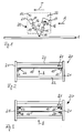
- the readout device is designed as a so-called line sensor, wherein the stimulation radiation source 11 is formed as a line light source which is, for example, a plurality of in a line perpendicular to the figure plane arranged laser diodes comprises.
- the detector 17 has in this case a plurality of also arranged in a line perpendicular to the plane of the figure radiation-sensitive surfaces, for example in the form of a so-called CCD arrays.
- the first optical device 13 is one or more, perpendicular to the plane of the figure extending cylindrical lenses, which stimulation radiation Focus 12 on the phosphor layer 1 in the plane of the figure.
- the named components of the read-out device are on a carrier 20 attached, which in turn with a receiving device, not shown is coupled and through this in the transport direction T via the phosphor layer. 1 can be performed. In this case, are carried by the read-out device successively different areas of the phosphor layer 1 read out, wherein an X-ray image stored in the phosphor layer 1 is read out.
- the carrier 20 essentially comprises two side parts 21, of which in the here selected side view only one can be seen.
- To the stable mechanical Connection of the side parts 21 are three connecting elements 22, preferably Tubes of glass or carbon fiber reinforced plastic, provided. Out Anschauigekeitconn are the side part 21 and the connecting elements 22 shown dashed or dotted.
- FIG. 2 shows a front view of a first variant of that shown in FIG Device in the direction of view A.
- a highly schematic component 10 of the read-out device shown in Fig. 1 shown is here only a highly schematic component 10 of the read-out device shown in Fig. 1 shown.
- the following Remarks regarding this component 10 apply accordingly to one or more of the components 11, 13, 15, 16 and 17 shown in FIG. 1 the readout device.
- the side parts 21 have in the illustrated embodiment, projections 23 and 24, to which the Component 10 of the read-out device by means of a first bearing 25 and a second bearing 26 is mounted.
- the first bearing 25 is configured such that this one translational degree of freedom in a first direction R1, whereby a Movement of the component 10 relative to the carrier 20 in the first direction R1 is possible.
- the other end of the component 10 is via a second bearing 26 mounted on the projection 24 of the side part 21, wherein the second bearing 26th has no translational degree of freedom in the first direction R1.
- Fig. 3 shows a front view of a second variant of the invention Device in which two components 10 and 10 'on the carrier 20 individually, i. independently of each other, are stored.
- Each of the components 10 and 10 ' is in each case via a first bearing 25 or 27 and a second bearing 26th or 28 is mounted on the side parts 21 of the carrier 20.
- the first two camps 25 and 27 are designed according to the invention so that they have a translatory Degree of freedom in the first direction R1 and thus have a movement the respective components 10 and 10 'relative to the carrier 20 in the first Allow direction R1.
- Characterized in that the two components 10 and 10 'respectively individually and independently of each other are mounted on the carrier 20, also whose movements in the first direction R1 are independent of each other.
- the components 10 and 10 ' are thus decoupled from each other, so that any Tensions due to different thermal expansion coefficients be avoided.
- the two first bearings 25 and 27 are respectively at the same (in Figure 3: at the right) end of the respective components 10 and 10 '.
- first bearing 25 of a component 10 and the first bearing 27 of the other component 10 'at the opposite ends (in Figure 3: on the right or at left end) of the respective components 10 and 10 ' is arranged.
- FIG. 4 shows a view of the component 10 shown in FIGS. 2 and 3 Viewing B.
- the component 10 has an elongated shape, which extends parallel to a longitudinal direction L.
- the first bearing 25 is located in Area of a first end 18 of the component 10, while the second bearing 26th in the region of a second end 19 of the component 10 is located.
- the longitudinal direction L runs along which the elongated shape of the component 10 extends, and the first direction R1, in which the component 10 can move, parallel to each other. This is special beneficial to tension due to length changes due to to avoid temperature fluctuations.
- the first and second bearings 25 or 26 are indicated only schematically in the representation selected here. you Structure will be explained in more detail below in connection with FIG.
- Fig. 5 shows the two ends 18 and 19 respectively as an enlarged section of in 4 shown in the component 10.
- the in the region of the first end 18 of Component 10 arranged first bearing 25 essentially comprises a in the Component 10 introduced groove 31 and a ball 32, which in the groove 31 in the first direction R1 is movable, for example by rolling and / or sliding.
- a circular recess 33 is provided, in which a ball 34 are partially sunk can.
- the second bearing 26 has no translational degrees of freedom. Beyond that by the second bearing 26 shown here rotatory degrees of freedom of the component 10 about a parallel to the first direction R1 extending axis of rotation as well as around a plane perpendicular to the plane of the figure obtained.
- FIG. 6 shows the two ends 18 and 19 of a variant of that shown in FIG. 4 Component 10 in an enlarged view.
- a third bearing 29 is provided in addition to the first bearing 25, which is both a translatory degree of freedom in the first direction R1 as well as a translational degree of freedom in a second direction R2 has.
- the third bearing 29 can be easily by a Realize ball on which the first end 18 of the component 10 rests and which in a circular recess in the support, in particular a projection 23, of the side part 21 of the carrier 20 (see Fig. 2) partially sunk is.
- the third bearing 29 in the region of the first bearing 25 is a tilt the first end 18 of the component 10 about a parallel to the longitudinal direction L of the component 10 extending axis of rotation prevented. To this way, voltages in the component 10 can be combined with high tilt stability prevented or reduced.
- a fourth bearing 30 with two translatory degrees of freedom in the first and second directions R1 and R2 may be provided. This will be the Tilting stability with respect to a parallel to the longitudinal direction L axis of rotation guaranteed with high reliability.
- Fig. 7 shows a section of the right side part 21 of the carrier with a of several implementation possibilities of the first bearing according to the invention 25.
- the component 10 is via a ball 32 mounted on the projection 23 of the side part 21.
- the ball 32 is in an in The projection introduced recess 35.
- the ball 32 is in the introduced into the component 10 groove 31, which serves as a guide.
- the component 10 is biased by a spring 37 against the ball 32 to an undesirable Jumping out of the ball and / or the component 10 from the camp to avoid.
- the spring 37 is preferably at a further projection 36 of the side part 21 attached.
- the second, third and fourth bearings 26, 29 and 30 can be correspondingly Realize manner, wherein the second bearing 26, the guide groove 31 by a round depression, similar to the recess 35, is to replace and in the third and fourth bearings 29 and 33, the optical component 10 in general no Has depression or guide groove.
Landscapes
- General Physics & Mathematics (AREA)
- Signal Processing (AREA)
- Physics & Mathematics (AREA)
- Health & Medical Sciences (AREA)
- Life Sciences & Earth Sciences (AREA)
- Molecular Biology (AREA)
- Engineering & Computer Science (AREA)
- Multimedia (AREA)
- Spectroscopy & Molecular Physics (AREA)
- High Energy & Nuclear Physics (AREA)
- Apparatus For Radiation Diagnosis (AREA)
- Facsimile Scanning Arrangements (AREA)
- Measurement Of Radiation (AREA)
- Radiography Using Non-Light Waves (AREA)
Priority Applications (4)
| Application Number | Priority Date | Filing Date | Title |
|---|---|---|---|
| DE502004003675T DE502004003675D1 (de) | 2004-04-02 | 2004-04-02 | Vorrichtung zum Auslesen von in einer Phosphorschicht gespeicherten Röntgeninformation |
| AT04101370T ATE361630T1 (de) | 2004-04-02 | 2004-04-02 | Vorrichtung zum auslesen von in einer phosphorschicht gespeicherten röntgeninformation |
| EP04101370A EP1585308B1 (fr) | 2004-04-02 | 2004-04-02 | Appareil pour lire des informations radiographiques d'un panneau luminescent d'enregistrement |
| US11/079,653 US7498598B2 (en) | 2004-04-02 | 2005-03-14 | System for reading out X-ray information stored in a phosphor layer |
Applications Claiming Priority (1)
| Application Number | Priority Date | Filing Date | Title |
|---|---|---|---|
| EP04101370A EP1585308B1 (fr) | 2004-04-02 | 2004-04-02 | Appareil pour lire des informations radiographiques d'un panneau luminescent d'enregistrement |
Publications (2)
| Publication Number | Publication Date |
|---|---|
| EP1585308A1 true EP1585308A1 (fr) | 2005-10-12 |
| EP1585308B1 EP1585308B1 (fr) | 2007-05-02 |
Family
ID=34896112
Family Applications (1)
| Application Number | Title | Priority Date | Filing Date |
|---|---|---|---|
| EP04101370A Expired - Lifetime EP1585308B1 (fr) | 2004-04-02 | 2004-04-02 | Appareil pour lire des informations radiographiques d'un panneau luminescent d'enregistrement |
Country Status (4)
| Country | Link |
|---|---|
| US (1) | US7498598B2 (fr) |
| EP (1) | EP1585308B1 (fr) |
| AT (1) | ATE361630T1 (fr) |
| DE (1) | DE502004003675D1 (fr) |
Families Citing this family (3)
| Publication number | Priority date | Publication date | Assignee | Title |
|---|---|---|---|---|
| EP1640800B1 (fr) * | 2004-09-22 | 2008-08-20 | Agfa-Gevaert HealthCare GmbH | Dispositif de lecture d'information radiographique stockée dans une plaque à mémoire luminescente |
| EP1640801B1 (fr) * | 2004-09-22 | 2008-08-20 | Agfa-Gevaert HealthCare GmbH | Dispositif et procédé de lecture d'information radiographique stockée dans une plaque à mémoire au phosphore |
| DE502005007861D1 (de) * | 2005-12-29 | 2009-09-17 | Agfa Gevaert Healthcare Gmbh | Antriebsvorrichtung für eine optische Abtasteinrichtung |
Citations (4)
| Publication number | Priority date | Publication date | Assignee | Title |
|---|---|---|---|---|
| EP0479153A2 (fr) * | 1990-10-02 | 1992-04-08 | Mita Industrial Co. Ltd. | Appareil de formation d'images avec une tête à LED |
| EP0963101A2 (fr) * | 1998-06-03 | 1999-12-08 | Agfa Corporation | Module capteur d'images, ajustable à six degrés de liberté, pour l'utilisation avec un dispositif d'acquisition d'images |
| EP1227653A2 (fr) * | 2001-01-19 | 2002-07-31 | Canon Kabushiki Kaisha | Dispositif de lecture d'image |
| EP1378766A1 (fr) * | 2002-07-02 | 2004-01-07 | Agfa-Gevaert AG | Dispositif et procédé pour lire les informations contenues dans une couche mémoire |
Family Cites Families (4)
| Publication number | Priority date | Publication date | Assignee | Title |
|---|---|---|---|---|
| US5440146A (en) * | 1994-03-31 | 1995-08-08 | Minnesota Mining And Manufacturing Company | Radiographic image reader |
| DE19946743C1 (de) * | 1999-09-29 | 2000-11-23 | Siemens Ag | Röntgendiagnostikeinrichtung mit einem Speicherleuchtschirm |
| JP4219549B2 (ja) * | 2000-12-20 | 2009-02-04 | 富士フイルム株式会社 | 放射線画像読取方法および装置 |
| JP3785372B2 (ja) * | 2002-02-25 | 2006-06-14 | 富士写真フイルム株式会社 | シート状画像記録担体の状態検知装置 |
-
2004
- 2004-04-02 AT AT04101370T patent/ATE361630T1/de not_active IP Right Cessation
- 2004-04-02 EP EP04101370A patent/EP1585308B1/fr not_active Expired - Lifetime
- 2004-04-02 DE DE502004003675T patent/DE502004003675D1/de not_active Expired - Lifetime
-
2005
- 2005-03-14 US US11/079,653 patent/US7498598B2/en not_active Expired - Fee Related
Patent Citations (4)
| Publication number | Priority date | Publication date | Assignee | Title |
|---|---|---|---|---|
| EP0479153A2 (fr) * | 1990-10-02 | 1992-04-08 | Mita Industrial Co. Ltd. | Appareil de formation d'images avec une tête à LED |
| EP0963101A2 (fr) * | 1998-06-03 | 1999-12-08 | Agfa Corporation | Module capteur d'images, ajustable à six degrés de liberté, pour l'utilisation avec un dispositif d'acquisition d'images |
| EP1227653A2 (fr) * | 2001-01-19 | 2002-07-31 | Canon Kabushiki Kaisha | Dispositif de lecture d'image |
| EP1378766A1 (fr) * | 2002-07-02 | 2004-01-07 | Agfa-Gevaert AG | Dispositif et procédé pour lire les informations contenues dans une couche mémoire |
Also Published As
| Publication number | Publication date |
|---|---|
| US20050218355A1 (en) | 2005-10-06 |
| ATE361630T1 (de) | 2007-05-15 |
| EP1585308B1 (fr) | 2007-05-02 |
| US7498598B2 (en) | 2009-03-03 |
| DE502004003675D1 (de) | 2007-06-14 |
Similar Documents
| Publication | Publication Date | Title |
|---|---|---|
| EP1482721A1 (fr) | Dispositif de saisie d'informations contenues dans une couche de phosphore | |
| DE10156275B4 (de) | Detektoranordnung und Detektionsverfahren | |
| DE4235549C2 (de) | Gerät zum Justieren einer Lichtquelleneinheit | |
| DE102015118199A1 (de) | Optisches medizinisches Instrument | |
| DE3028899C2 (fr) | ||
| DE112016001820B4 (de) | Laservorrichtung und licht-erzeugungsvorrichtung für extrem ultraviolette strahlung | |
| DE4435112C2 (de) | Vorrichtung zum Ausrichten einer Röntgenkassette | |
| EP1585308B1 (fr) | Appareil pour lire des informations radiographiques d'un panneau luminescent d'enregistrement | |
| DE60032485T2 (de) | Mehrstrahl diodengepumpter optisches abbildungssystem | |
| DE102008030893A1 (de) | Streustrahlungskollimator, Strahlungdetektor und Strahlungserfassungseinrichtung | |
| EP1691216A1 (fr) | Système radiographique et méthode d'enregistrement des radiographies dans des feuilles photostimulables | |
| DE102005028904B4 (de) | Röntgenstrahlenerzeuger für ein Röntgengerät mit Röntgenlinsenmodul | |
| EP1482328B1 (fr) | Dispositif de détection d'informations dans une couche de matière luminéscente | |
| EP1378766B1 (fr) | Dispositif et procédé pour lire les informations contenues dans une couche mémoire | |
| EP1804082B1 (fr) | Dispositif destiné à la lecture d'informations radiographiques stockées dans une couche fluorescente de mémoire et module de radiographie | |
| DE3918698C1 (fr) | ||
| DE19937416C2 (de) | Vorrichtung zum Auslesen von in einer Speicherschicht abgespeicherten Informationen | |
| BE1014283A3 (fr) | Rontgendiagnostikeinrichtung mit einem speicherleuchtschirm. | |
| EP0475544A1 (fr) | Dispositif d'isolation acoustique pour caméra | |
| EP1378767A1 (fr) | Dispositif et procédé pour lire les informations contenues dans une couche mémoire | |
| DE10301961A1 (de) | Optische Linseneinrichtung für einen Scanner | |
| DE102009049663A1 (de) | Feldemission-Röntgenquelle mit magnetischem Brennpunkt-Screening | |
| DE112015005596T5 (de) | Ladungsteilchen-strahlvorrichtung | |
| DE2740998A1 (de) | Roentgendiagnostikeinrichtung fuer durchleuchtung | |
| DE19521034A1 (de) | Lichttonkopf und Tonfilmprojektor damit |
Legal Events
| Date | Code | Title | Description |
|---|---|---|---|
| PUAI | Public reference made under article 153(3) epc to a published international application that has entered the european phase |
Free format text: ORIGINAL CODE: 0009012 |
|
| AK | Designated contracting states |
Kind code of ref document: A1 Designated state(s): AT BE BG CH CY CZ DE DK EE ES FI FR GB GR HU IE IT LI LU MC NL PL PT RO SE SI SK TR |
|
| AX | Request for extension of the european patent |
Extension state: AL LT LV MK |
|
| RAP1 | Party data changed (applicant data changed or rights of an application transferred) |
Owner name: AGFA-GEVAERT HEALTHCARE GMBH |
|
| 17P | Request for examination filed |
Effective date: 20060412 |
|
| AKX | Designation fees paid |
Designated state(s): AT BE BG CH CY CZ DE DK EE ES FI FR GB GR HU IE IT LI LU MC NL PL PT RO SE SI SK TR |
|
| GRAP | Despatch of communication of intention to grant a patent |
Free format text: ORIGINAL CODE: EPIDOSNIGR1 |
|
| GRAS | Grant fee paid |
Free format text: ORIGINAL CODE: EPIDOSNIGR3 |
|
| GRAA | (expected) grant |
Free format text: ORIGINAL CODE: 0009210 |
|
| AK | Designated contracting states |
Kind code of ref document: B1 Designated state(s): AT BE BG CH CY CZ DE DK EE ES FI FR GB GR HU IE IT LI LU MC NL PL PT RO SE SI SK TR |
|
| PG25 | Lapsed in a contracting state [announced via postgrant information from national office to epo] |
Ref country code: FI Free format text: LAPSE BECAUSE OF FAILURE TO SUBMIT A TRANSLATION OF THE DESCRIPTION OR TO PAY THE FEE WITHIN THE PRESCRIBED TIME-LIMIT Effective date: 20070502 |
|
| REG | Reference to a national code |
Ref country code: GB Ref legal event code: FG4D Free format text: NOT ENGLISH |
|
| GBT | Gb: translation of ep patent filed (gb section 77(6)(a)/1977) |
Effective date: 20070502 |
|
| REG | Reference to a national code |
Ref country code: CH Ref legal event code: EP |
|
| REG | Reference to a national code |
Ref country code: IE Ref legal event code: FG4D Free format text: LANGUAGE OF EP DOCUMENT: GERMAN |
|
| REF | Corresponds to: |
Ref document number: 502004003675 Country of ref document: DE Date of ref document: 20070614 Kind code of ref document: P |
|
| PG25 | Lapsed in a contracting state [announced via postgrant information from national office to epo] |
Ref country code: SE Free format text: LAPSE BECAUSE OF FAILURE TO SUBMIT A TRANSLATION OF THE DESCRIPTION OR TO PAY THE FEE WITHIN THE PRESCRIBED TIME-LIMIT Effective date: 20070802 |
|
| PG25 | Lapsed in a contracting state [announced via postgrant information from national office to epo] |
Ref country code: ES Free format text: LAPSE BECAUSE OF FAILURE TO SUBMIT A TRANSLATION OF THE DESCRIPTION OR TO PAY THE FEE WITHIN THE PRESCRIBED TIME-LIMIT Effective date: 20070813 |
|
| ET | Fr: translation filed | ||
| NLV1 | Nl: lapsed or annulled due to failure to fulfill the requirements of art. 29p and 29m of the patents act | ||
| PG25 | Lapsed in a contracting state [announced via postgrant information from national office to epo] |
Ref country code: PL Free format text: LAPSE BECAUSE OF FAILURE TO SUBMIT A TRANSLATION OF THE DESCRIPTION OR TO PAY THE FEE WITHIN THE PRESCRIBED TIME-LIMIT Effective date: 20070502 |
|
| REG | Reference to a national code |
Ref country code: IE Ref legal event code: FD4D |
|
| PG25 | Lapsed in a contracting state [announced via postgrant information from national office to epo] |
Ref country code: NL Free format text: LAPSE BECAUSE OF FAILURE TO SUBMIT A TRANSLATION OF THE DESCRIPTION OR TO PAY THE FEE WITHIN THE PRESCRIBED TIME-LIMIT Effective date: 20070502 Ref country code: PT Free format text: LAPSE BECAUSE OF FAILURE TO SUBMIT A TRANSLATION OF THE DESCRIPTION OR TO PAY THE FEE WITHIN THE PRESCRIBED TIME-LIMIT Effective date: 20071002 Ref country code: DK Free format text: LAPSE BECAUSE OF FAILURE TO SUBMIT A TRANSLATION OF THE DESCRIPTION OR TO PAY THE FEE WITHIN THE PRESCRIBED TIME-LIMIT Effective date: 20070502 Ref country code: CZ Free format text: LAPSE BECAUSE OF FAILURE TO SUBMIT A TRANSLATION OF THE DESCRIPTION OR TO PAY THE FEE WITHIN THE PRESCRIBED TIME-LIMIT Effective date: 20070502 Ref country code: BG Free format text: LAPSE BECAUSE OF FAILURE TO SUBMIT A TRANSLATION OF THE DESCRIPTION OR TO PAY THE FEE WITHIN THE PRESCRIBED TIME-LIMIT Effective date: 20070802 Ref country code: IE Free format text: LAPSE BECAUSE OF FAILURE TO SUBMIT A TRANSLATION OF THE DESCRIPTION OR TO PAY THE FEE WITHIN THE PRESCRIBED TIME-LIMIT Effective date: 20070502 Ref country code: SI Free format text: LAPSE BECAUSE OF FAILURE TO SUBMIT A TRANSLATION OF THE DESCRIPTION OR TO PAY THE FEE WITHIN THE PRESCRIBED TIME-LIMIT Effective date: 20070502 |
|
| PG25 | Lapsed in a contracting state [announced via postgrant information from national office to epo] |
Ref country code: SK Free format text: LAPSE BECAUSE OF FAILURE TO SUBMIT A TRANSLATION OF THE DESCRIPTION OR TO PAY THE FEE WITHIN THE PRESCRIBED TIME-LIMIT Effective date: 20070502 |
|
| PLBE | No opposition filed within time limit |
Free format text: ORIGINAL CODE: 0009261 |
|
| STAA | Information on the status of an ep patent application or granted ep patent |
Free format text: STATUS: NO OPPOSITION FILED WITHIN TIME LIMIT |
|
| 26N | No opposition filed |
Effective date: 20080205 |
|
| PG25 | Lapsed in a contracting state [announced via postgrant information from national office to epo] |
Ref country code: IT Free format text: LAPSE BECAUSE OF FAILURE TO SUBMIT A TRANSLATION OF THE DESCRIPTION OR TO PAY THE FEE WITHIN THE PRESCRIBED TIME-LIMIT Effective date: 20070502 Ref country code: GR Free format text: LAPSE BECAUSE OF FAILURE TO SUBMIT A TRANSLATION OF THE DESCRIPTION OR TO PAY THE FEE WITHIN THE PRESCRIBED TIME-LIMIT Effective date: 20070803 |
|
| PG25 | Lapsed in a contracting state [announced via postgrant information from national office to epo] |
Ref country code: RO Free format text: LAPSE BECAUSE OF FAILURE TO SUBMIT A TRANSLATION OF THE DESCRIPTION OR TO PAY THE FEE WITHIN THE PRESCRIBED TIME-LIMIT Effective date: 20070502 |
|
| BERE | Be: lapsed |
Owner name: AGFA-GEVAERT HEALTHCARE G.M.B.H. Effective date: 20080430 |
|
| PG25 | Lapsed in a contracting state [announced via postgrant information from national office to epo] |
Ref country code: MC Free format text: LAPSE BECAUSE OF NON-PAYMENT OF DUE FEES Effective date: 20080430 |
|
| REG | Reference to a national code |
Ref country code: CH Ref legal event code: PL |
|
| PG25 | Lapsed in a contracting state [announced via postgrant information from national office to epo] |
Ref country code: EE Free format text: LAPSE BECAUSE OF FAILURE TO SUBMIT A TRANSLATION OF THE DESCRIPTION OR TO PAY THE FEE WITHIN THE PRESCRIBED TIME-LIMIT Effective date: 20070502 Ref country code: LI Free format text: LAPSE BECAUSE OF NON-PAYMENT OF DUE FEES Effective date: 20080430 Ref country code: CH Free format text: LAPSE BECAUSE OF NON-PAYMENT OF DUE FEES Effective date: 20080430 |
|
| PG25 | Lapsed in a contracting state [announced via postgrant information from national office to epo] |
Ref country code: BE Free format text: LAPSE BECAUSE OF NON-PAYMENT OF DUE FEES Effective date: 20080430 |
|
| PG25 | Lapsed in a contracting state [announced via postgrant information from national office to epo] |
Ref country code: CY Free format text: LAPSE BECAUSE OF FAILURE TO SUBMIT A TRANSLATION OF THE DESCRIPTION OR TO PAY THE FEE WITHIN THE PRESCRIBED TIME-LIMIT Effective date: 20070502 |
|
| PG25 | Lapsed in a contracting state [announced via postgrant information from national office to epo] |
Ref country code: AT Free format text: LAPSE BECAUSE OF NON-PAYMENT OF DUE FEES Effective date: 20080402 |
|
| REG | Reference to a national code |
Ref country code: FR Ref legal event code: CA |
|
| PG25 | Lapsed in a contracting state [announced via postgrant information from national office to epo] |
Ref country code: LU Free format text: LAPSE BECAUSE OF NON-PAYMENT OF DUE FEES Effective date: 20080402 Ref country code: HU Free format text: LAPSE BECAUSE OF FAILURE TO SUBMIT A TRANSLATION OF THE DESCRIPTION OR TO PAY THE FEE WITHIN THE PRESCRIBED TIME-LIMIT Effective date: 20071103 |
|
| PG25 | Lapsed in a contracting state [announced via postgrant information from national office to epo] |
Ref country code: TR Free format text: LAPSE BECAUSE OF FAILURE TO SUBMIT A TRANSLATION OF THE DESCRIPTION OR TO PAY THE FEE WITHIN THE PRESCRIBED TIME-LIMIT Effective date: 20070502 |
|
| PGFP | Annual fee paid to national office [announced via postgrant information from national office to epo] |
Ref country code: FR Payment date: 20120307 Year of fee payment: 9 |
|
| PGFP | Annual fee paid to national office [announced via postgrant information from national office to epo] |
Ref country code: GB Payment date: 20120306 Year of fee payment: 9 |
|
| REG | Reference to a national code |
Ref country code: DE Ref legal event code: R084 Ref document number: 502004003675 Country of ref document: DE Effective date: 20131026 |
|
| GBPC | Gb: european patent ceased through non-payment of renewal fee |
Effective date: 20130402 |
|
| PG25 | Lapsed in a contracting state [announced via postgrant information from national office to epo] |
Ref country code: GB Free format text: LAPSE BECAUSE OF NON-PAYMENT OF DUE FEES Effective date: 20130402 |
|
| REG | Reference to a national code |
Ref country code: FR Ref legal event code: ST Effective date: 20131231 |
|
| PG25 | Lapsed in a contracting state [announced via postgrant information from national office to epo] |
Ref country code: FR Free format text: LAPSE BECAUSE OF NON-PAYMENT OF DUE FEES Effective date: 20130430 |
|
| PGFP | Annual fee paid to national office [announced via postgrant information from national office to epo] |
Ref country code: DE Payment date: 20140304 Year of fee payment: 11 |
|
| REG | Reference to a national code |
Ref country code: DE Ref legal event code: R119 Ref document number: 502004003675 Country of ref document: DE |
|
| PG25 | Lapsed in a contracting state [announced via postgrant information from national office to epo] |
Ref country code: DE Free format text: LAPSE BECAUSE OF NON-PAYMENT OF DUE FEES Effective date: 20151103 |