EP1585370A2 - Mikrowellen Backofen für Keramikmaterialen - Google Patents
Mikrowellen Backofen für Keramikmaterialen Download PDFInfo
- Publication number
- EP1585370A2 EP1585370A2 EP05007657A EP05007657A EP1585370A2 EP 1585370 A2 EP1585370 A2 EP 1585370A2 EP 05007657 A EP05007657 A EP 05007657A EP 05007657 A EP05007657 A EP 05007657A EP 1585370 A2 EP1585370 A2 EP 1585370A2
- Authority
- EP
- European Patent Office
- Prior art keywords
- wall
- temperature
- heating
- microwave
- baking
- Prior art date
- Legal status (The legal status is an assumption and is not a legal conclusion. Google has not performed a legal analysis and makes no representation as to the accuracy of the status listed.)
- Withdrawn
Links
Images

Classifications
-
- H—ELECTRICITY
- H05—ELECTRIC TECHNIQUES NOT OTHERWISE PROVIDED FOR
- H05B—ELECTRIC HEATING; ELECTRIC LIGHT SOURCES NOT OTHERWISE PROVIDED FOR; CIRCUIT ARRANGEMENTS FOR ELECTRIC LIGHT SOURCES, IN GENERAL
- H05B6/00—Heating by electric, magnetic or electromagnetic fields
- H05B6/64—Heating using microwaves
- H05B6/647—Aspects related to microwave heating combined with other heating techniques
- H05B6/6473—Aspects related to microwave heating combined with other heating techniques combined with convection heating
Definitions
- the present invention relates to a microwave baking furnace for baking an object to be baked which is made of a pottery material or a fine ceramics material.
- the microwave uniformly heats each part of the object to be baked in principle.
- an atmosphere temperature is considerably lower than a surface temperature of the object to be baked at the beginning of a baking process, heat is radiated from the surface of the object to be baked. As a result, a temperature gradient occurs between a central portion of the object to be baked and the surface thereof and crack easily occurs.
- an object to be baked is made of a material such as alumina or silica, which is a main material of ceramics and has a low dielectric loss at room temperature, there is a problem in that the energy efficiency of microwave heating in a low-temperature zone is low.
- microwave baking furnace for suppressing such a temperature gradient and for reducing the occurrence of the crack
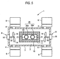
- a microwave baking furnace having the structure shown in FIG 5 is suggested (for example, refer to Japanese Unexamined Patent Application Publication No. 2002-130960 (Page 3, FIG 1)).
- a microwave baking furnace 1 includes a cavity 3 partitioning a microwave space 2, a magnetron 6 as a microwave generating means which is connected to the cavity 3 via a waveguide 4 and radiates microwave to the inside of the cavity 3, a microwave stirring means 8 for stirring the microwave radiated to the inside of the cavity, a blanket 10 arranged inside the cavity 3, and an auxiliary blanket 11 surrounding the blanket 10.
- the cavity 3 reflects the microwave toward the microwave space 2 at least at the inside thereof and prevents the microwave from leaking.
- the microwave stirring means 8 has stirring blades 14 disposed inside the cavity 3, a driving motor 16 disposed outside the cavity 3, a rotation transmitting shaft 18 for transmitting the rotation of the driving motor 16 to the stirring blades 14.
- the atmosphere in the cavity 3 is stirred by the rotation of the stirring blades 14.
- the blanket 10 partitions a baking chamber 23 in which an object to be baked is disposed.
- a partition wall 25 partitioning the baking chamber 23 is constructed as a double wall structure of an outer wall 25a and an inner wall 25b.
- the outer wall 25a is made of a material which has insulating properties and permits the microwaves to be transmitted therethrough. Specifically, the outer wall 25a is made of alumina fiber or foamed alumina.
- the inner wall 25b is made of a dielectric material which self-heats by the microwave radiated thereto from the outside and which can transmit part of the microwaves to the inside of the baking chamber 23.
- a heating material for a high-temperature zone which self-heats equally to or more than an object to be baked in a high-temperature zone near a baking temperature.
- a mullite-based material is preferable.
- the auxiliary blanket 11 makes the periphery of the blanket 10 an insulating space and suppresses the occurrence of a temperature gradient due to the heat radiation from the blanket 10 to the surrounding atmosphere thereof. Therefore, the auxiliary blanket 11 is made of an insulating material such as alumina fiber or foamed alumina, which has insulating properties and permits microwaves to be transmitted therethrough, similar to the outer wall 25a of the blanket 10.
- the partition wall 25 of the blanket 10, which partitions the baking chamber 23 is comprised of the inner wall 25b capable of transmitting part of microwaves to the inside of the baking chamber 23 while self-heating by the microwave, and the outer wall 25a which is made of an insulating material and surrounds the inner wall, the atmosphere temperature inside the baking chamber 23 rises by the self-heating of the inner wall 25b and the heat radiation from the baking chamber 23 to the outside is suppressed by the outer wall 25a, simultaneously with the progress of the microwave heating to an object to be baked.
- the atmosphere inside the baking chamber 23 is kept stable at a high temperature according to the temperature rising of the object 21 to be baked so that the heat radiation from the surface of the object 21 to be baked to the periphery thereof can be suppressed.
- the outer wall 25a for the main purpose of insulation and the inner wall 25b for the main purpose of heating constitute a double wall structure in a state in which they are closely adhered to each other. Therefore, when the temperature of the inner wall 25b rises to a high-temperature zone at a time or the inner wall is cooled down after baking, a significant thermal shock acts between the outer wall 25a and the inner wall 25b due to the difference in thermal expansion therebetween. As a result, the inner wall 25b made of, for example, a mullite-based material may be easily broken, and the life span of the double wall structure for preventing the occurrence of the temperature gradient may be shortened.
- the mullite-based material used for the inner wall 25b shows high heating characteristics near the baking temperature of the object 21 to be baked, but shows low heating characteristics in a low-temperature zone including room temperature. Therefore, at the time of initial temperature rising in a low-temperature zone by the microwave heating, the self-heating value of the inner wall 25b is small. Thus, a problem remains unsolved that when an object to be baked whose dielectric loss is small at room temperature is baked, it is difficult to efficiently heat the object to be baked, similar to the conventional baking furnace.
- An object of the present invention is to provide a microwave baking furnace capable of reliably preventing the occurrence of a temperature gradient in a baking chamber for a long time by extending the life span of a partition wall having a double wall structure without damaging an inner wall constituting a partition wall due to a thermal shock, in a partition wall partitioning the baking chamber and having the double wall structure of the inner wall and the outer wall. Further, another object of the present invention is to provide a microwave baking furnace capable of efficiently realizing the temperature rising in a low-temperature zone and a high-temperature zone only by microwave heating, and of efficiently baking an object to be baked even when the object to be baked whose dielectric loss is small at room temperature is baked.
- a clearance which serves as a heat convection path inside the baking chamber, is secured between the outer wall and the inner wall, so that the difference in temperature between the outer wall and the inner wall is reduced by the convection flowing through the clearance.
- the inner wall can move relatively by a predetermined distance in all directions, the outer wall and the inner wall are free from mutual constraint caused by their thermal expansion, and a thermal shock to the outer wall and inner wall can be reduced at the time of temperature rising by microwave heating.
- the inner wall is free from breakage caused by the thermal shock, and it is possible to reliably prevent the occurrence of a temperature gradient in a baking chamber for a long time by extending the life span of a partition wall of a double wall structure.
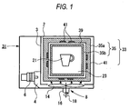
- FIG. 1 illustrates a microwave baking furnace according to an embodiment of the present invention.
- a microwave baking furnace 31 in this embodiment bakes an object 21 to be baked made of a material such as a pottery material and fine ceramics with microwave heating.
- the microwave baking furnace 31 includes a cavity 3 partitioning a microwave space 2, a magnetron 6 as a microwave generating means which is connected to the cavity 3 via a waveguide 4 and radiates a microwave to the inside of the cavity 3, a microwave stirring means 8 for stirring the microwave irradiated to the inside of the cavity 3, and a heating element 33 which is placed in the cavity 3 and will be described later.
- the cavity 3 reflects the microwave to the microwave space 2 at least at the inside thereof and prevents the microwave from leaking.
- the microwave stirring means 8 comprises stirring blades 14 arranged inside the cavity 3, a driving motor 16 arranged outside the cavity 3, a rotation transmitting shaft 18 for transmitting the rotation of the driving motor 16 to the stirring blades 14.
- the atmosphere inside the cavity 3 is stirred by the rotation of the stirring blades 14.
- the heating element 33 forms a baking chamber 23 in which an object 21 to be baked is placed, and self-heats to heat the object 21 to be baked such that a partition wall 35 partitioning the baking chamber 23 is constructed as a two-layer structure of an outer wall 35a and an inner wall 35b.
- the outer wall 35a is made of a material such as alumina fiber or foamed alumina, which has heat-insulating properties and permits the microwaves to be transmitted therethrough.
- the inner wall 35b is made of a dielectric material which self-heats by the microwave radiated from the outside, and can transmit part of the radiated microwaves to the object 21 to be baked disposed inside the baking chamber 23.
- the inner wall 35b is made of a heat generating material for a high-temperature zone which self-heats in the high-temperature zone which becomes principally a baking temperature by the microwave radiation.
- the generating material for the high-temperature zone it is needed that a heating value per unit volume by the microwave heating is larger than that of the object 21 to be baked.
- a mullite-based material, a silicon nitride-based material, alumina, etc. can be exemplified as the heating material.
- the heating material having an appropriate heating value is selected depending on the temperature characteristics of the object 21 to be baked.
- heating material for the high-temperature zone it is preferable that metal oxide having a large microwave absorption rate (for example, magnesia, zirconia, iron oxide, etc.), or an inorganic material (for example, silicon carbide) is added to the above-described heating material with a small amount to adjust the heating characteristics.
- metal oxide having a large microwave absorption rate for example, magnesia, zirconia, iron oxide, etc.
- an inorganic material for example, silicon carbide
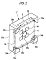
- each of a top face, a bottom face, a front face, a rear face, a left face, and a right face, which partitions the baking chamber 23, is comprised of a partition wall unit 37 shown in FIG 2.
- the respective faces are detachably assembled to each other.
- the partition wall 37 is constructed as a double wall structure of the outer wall 35a and the inner wall 35b, in which the thin flat plate-shaped inner wall 35b is attached to the inner side of the thick flat plate-shaped outer wall 35a.
- the outer wall 35a is constructed such that holding grooves 38b having peripheral edges of the inner wall 35b fitted thereinto are formed at braces 38a protruding from four corners thereof.
- the installation position is set such that a clearance 39 which becomes a convection path of heat inside the baking chamber 23 is secured between the outer wall 35a and the inner wall 35b.
- a heat flow inside the baking chamber 23 flows into the convection path formed by the clearance 39 from an opening formed in the outer circumference of the inner wall 35b to eliminate the difference in temperature inside the clearance 39.
- the depth or width of the holding grooves 38b is set such that the inner wall 35b can move relative to the outer wall 35a covering the outer side of the inner wall 35b by a predetermined distance in all directions (including a face direction and a thickness direction of the plate).
- the unit 37 according to the present embodiment is attached such that the clearance 39 which becomes a convection path of heat inside the baking chamber is secured between the outer wall 35a and the inner wall 35b, and each inner wall 35b can move relative to the outer wall 35a covering the outer side thereof by a predetermined distance in all directions.
- auxiliary heating elements 41 made of a material for a low-temperature zone, which self-heats in a zone of a low temperature including, principally, room temperature by microwave radiation and transmits part of the microwaves radiated thereto, is buried in the outer wall 35a.
- a position restriction protrusion 38c which prevents a central portion of the inner wall 35b from being flexed and contacting the outer wall 35a, protrudes from the central portion of the outer wall 35a.
- the position restriction protrusion 38c serves as a spacer which prevents the central portion of the inner wall 35b being flexed and contacting the auxiliary heating elements 41 and secures the clearance 39 between the outer wall 35a and the inner wall 35b.
- a dielectric material As a heating material for a low-temperature zone, which is used as the auxiliary heating elements 41, a dielectric material is used.
- the dielectric material shows a heating value larger than that of a heating material for a high temperature such as a mullite-based material which is used for the inner wall 35b, from the low-temperature zone including room temperature to a temperature less than the high-temperature zone which becomes a baking temperature, and shows a heating value equal to or less than that of the heating material for high-temperature zone in the high-temperature zone which becomes the baking temperature.
- the heating material for the low-temperature zone which is used for the auxiliary heating elements 41 a material having superior microwave absorption properties is used. At room temperature, such a material shows a heating value per unit volume by the microwave, which is from several times to several tens times that of a material constituting the object 21 to be baked, and in a high-temperature zone which becomes a baking temperature, shows a heating value equal to or less than that of the heating material for a high-temperature zone.
- magnesia, zirconia, iron oxide, silicon carbide, etc. can be exemplified.
- the auxiliary heating elements 41 are buried in an inner surface of the outer wall 35a within a range corresponding to a central portion of the inner wall 35b, as a small-sized chip having a spherical or rectangular parallelepiped shape.
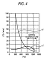
- FIG 4 illustrates the relationship between a heating temperature of the inner wall 35b and the auxiliary heating elements 41 and a rising temperature per unit time in heating by a microwave.
- a curved line f1 represents the relationship between the heating temperature and the rising temperature per unit time in a case in which a mullite-based material is used as a heating material for a high-temperature zone.
- a curved line f2 represents the relationship between the heating temperature and the rising temperature per unit time in a case in which silicon carbide is used as a heating material for a low-temperature zone.
- the heating element 33 rises in temperature by the microwave heating, and, at the same time, the object to be baked positioned inside the baking chamber 23 rises in temperature by the microwave transmitted through the heating element 33.
- the temperature inside the baking chamber 23 rises by the self-heating of the inner wall 35b concurrently with the progress of the microwave heating of the object 21 to be baked, and heat radiation from the baking chamber 23 and the inner wall 35b toward the outside can be suppressed by the outer wall 35a having superior insulating properties.
- the atmosphere inside the baking chamber 23 is kept stable at a high temperature according to the rising in temperature of the object 21 to be baked, the heat radiation from the surface of the object 21 to be baked toward the surrounding atmosphere thereof can be suppressed.
- the clearance 39 which serves as a heat convection path inside the baking chamber 23 is secured between the outer wall 35a and the inner wall 35b so that the difference in temperature between the outer wall 35a and the inner wall 35b is reduced by the convection flowing through the clearance 39.
- the inner wall 35b can move relatively in all directions, the outer wall 35a and the inner wall 35b are free from mutual constraint caused by their thermal expansion, and a thermal shock to the outer wall 35a and inner wall 35b can be reduced at the time of temperature rising by the microwave heating.
- the inner wall 35b is free from damage caused by the thermal shock, and it is possible to reliably prevent the occurrence of the temperature gradient in the baking chamber 23 for a long time by extending the life span of the partition wall 35 having a double wall structure.
- the auxiliary heating elements 41 which are made of a heating material for a low-temperature zone and are buried in the outer wall 35a of the partition wall 35 of the heating element 33, heat with a high degree of energy efficiency and accelerate the rise in the ambient temperature. Therefore, when the microwave proceeds and the temperature of the partition wall 35 of the heating element 33 rises to the predetermined high-temperature zone, the heating material for a high-temperature zone which forms the inner wall 35b heats with a high heating efficiency and raises the ambient temperature.
- the object 21 to be baked is made of a material such as alumina or silica, which is a main material of ceramics whose dielectric loss is small at room temperature, it is possible to bake it smoothly with a high degree of energy efficiency.
- the ambient temperature rises stably from the low-temperature zone to the high-temperature zone by the heat radiation from the heating material for the low-temperature zone or the heating material for the high-temperature zone
- the temperature of atmosphere inside the baking chamber, which is partitioned by the heating element 33, and the microwave space outside the heating element 33 rises similarly to that of the object 21 to be baked, and the difference in temperature between the object 21 to be baked and the surrounding atmosphere can be suppressed.
- the heat radiation of the object 21 to be baked from the low-temperature zone to the high-temperature zone can be suppressed, and the temperature gradient between the surface and an inner deep portion of the object 21 to be baked can be prevented from occurring.
- a dielectric material is used as a heating material for a low-temperature zone, which is used as the auxiliary heating elements 41.
- the dielectric material shows a heating value larger than that of a heating material for a high temperature zone such as a mullite-based material which is used as the inner wall 35b, from a low-temperature zone including room temperature to a temperature zone less than the high-temperature zone which becomes a baking temperature, and shows a heating value equal to or less than that of the heating material for high-temperature zone in the high-temperature zone which becomes the baking temperature.
- the auxiliary heating elements 41 are buried in the outer wall 35a within a range corresponding to the central region of the inner wall 35b, the heating of the inner wall 35b by the auxiliary heating elements 41 made of a heating material for a low-temperature zone is focused on the central portion of the inner wall 35b and it does not affect the periphery of the inner wall 35b in which local thermal deformation may be easily caused.
- the inner wall 35b disperses the thermal expansion caused by heating of the auxiliary heating elements 41 to a range of the central region so that it is possible to prevent large thermal deformation from being caused locally at the peripheral portion supported by the outer wall 35a and to prevent the breakage of the inner wall 35b caused by the rapid deformation at the peripheral portion. Therefore, the life span of the inner wall 35b can be extended.
- connection structure of the outer wall 35a and the inner wall 35b to secure the clearance between the outer wall 35a and the inner wall 35b, and the structure for supporting the inner wall 35b such that it can move by a predetermined distance in all directions are not limited to the structure illustrated in the above-described embodiment.
Landscapes
- Physics & Mathematics (AREA)
- Electromagnetism (AREA)
- Furnace Details (AREA)
- Constitution Of High-Frequency Heating (AREA)
- Furnace Housings, Linings, Walls, And Ceilings (AREA)
- Muffle Furnaces And Rotary Kilns (AREA)
Applications Claiming Priority (2)
| Application Number | Priority Date | Filing Date | Title |
|---|---|---|---|
| JP2004112856A JP2005299948A (ja) | 2004-04-07 | 2004-04-07 | マイクロ波焼成炉 |
| JP2004112856 | 2004-04-07 |
Publications (2)
| Publication Number | Publication Date |
|---|---|
| EP1585370A2 true EP1585370A2 (de) | 2005-10-12 |
| EP1585370A3 EP1585370A3 (de) | 2008-01-16 |
Family
ID=34909497
Family Applications (1)
| Application Number | Title | Priority Date | Filing Date |
|---|---|---|---|
| EP05007657A Withdrawn EP1585370A3 (de) | 2004-04-07 | 2005-04-07 | Mikrowellen Backofen für Keramikmaterialen |
Country Status (4)
| Country | Link |
|---|---|
| US (1) | US7315012B2 (de) |
| EP (1) | EP1585370A3 (de) |
| JP (1) | JP2005299948A (de) |
| CN (1) | CN100432007C (de) |
Families Citing this family (5)
| Publication number | Priority date | Publication date | Assignee | Title |
|---|---|---|---|---|
| JP5787289B2 (ja) * | 2011-06-20 | 2015-09-30 | ミクロ電子株式会社 | マイクロ波を応用した加熱装置 |
| MX2017002109A (es) * | 2014-08-22 | 2017-08-02 | Novelis Inc | Ensambles de soporte y compresion paradispositivo curvilineo de transferencia de metal fundido. |
| US10245574B1 (en) * | 2017-06-09 | 2019-04-02 | Gjergji Josif Shore | Microwave reactor vessel |
| CN108279174A (zh) * | 2018-02-06 | 2018-07-13 | 沈阳航空航天大学 | 一种材料的剪切破坏温度的检测方法及装置 |
| KR102054946B1 (ko) * | 2019-04-08 | 2019-12-12 | (주)현대에스엔티 | 마이크로파 전기로 |
Citations (1)
| Publication number | Priority date | Publication date | Assignee | Title |
|---|---|---|---|---|
| JP2002130960A (ja) | 2000-10-19 | 2002-05-09 | Natl Inst For Fusion Science | 焼成炉、焼成体の製造方法及び焼成体 |
Family Cites Families (14)
| Publication number | Priority date | Publication date | Assignee | Title |
|---|---|---|---|---|
| GB1268718A (en) * | 1969-05-21 | 1972-03-29 | Microwave Furnace & Kiln Consu | Microwave kiln |
| JPS5925939B2 (ja) | 1979-03-02 | 1984-06-22 | 三菱電機株式会社 | マイクロ波加熱炉 |
| DE19940123A1 (de) * | 1999-08-24 | 2001-03-01 | Bsh Bosch Siemens Hausgeraete | Steuer- oder Regeleinrichtung eines Kochherdes |
| GB2341677B (en) * | 1999-11-20 | 2000-12-27 | Merrychef Ltd | Ovens with catalytic converters |
| US6494130B2 (en) * | 2000-02-04 | 2002-12-17 | The Garland Group | Cooking apparatus insulated by non-fibrous means |
| DE10049847B4 (de) * | 2000-04-19 | 2005-12-01 | Lg Electronics Inc. | Mikrowellenherd |
| JP2003075077A (ja) * | 2001-09-05 | 2003-03-12 | Natl Inst For Fusion Science | マイクロ波焼成炉およびマイクロ波焼成方法 |
| US6689996B2 (en) * | 2001-12-07 | 2004-02-10 | Samsung Electronics Co., Ltd. | Microwave oven and method of controlling thereof |
| JP3799454B2 (ja) * | 2002-03-19 | 2006-07-19 | 大学共同利用機関法人自然科学研究機構 | 焼成炉 |
| JP2003302166A (ja) * | 2002-04-11 | 2003-10-24 | Denso Corp | マイクロ波焼成炉およびマイクロ波焼成方法 |
| US6608292B1 (en) * | 2002-07-26 | 2003-08-19 | Neal Patrick Barnes | Microwave grilling appliance |
| US6723970B1 (en) * | 2003-01-27 | 2004-04-20 | Maytag Corporation | Ventilation system for a cooking appliance |
| US6761159B1 (en) * | 2003-03-12 | 2004-07-13 | Maytag Corporation | Exhaust cooling system for a cooking appliance |
| US6772752B1 (en) * | 2003-04-10 | 2004-08-10 | Maytag Corporation | Cooling system airflow sensor for a cooking appliance |
-
2004
- 2004-04-07 JP JP2004112856A patent/JP2005299948A/ja active Pending
-
2005
- 2005-04-07 US US11/100,466 patent/US7315012B2/en not_active Expired - Fee Related
- 2005-04-07 CN CNB2005100638136A patent/CN100432007C/zh not_active Expired - Fee Related
- 2005-04-07 EP EP05007657A patent/EP1585370A3/de not_active Withdrawn
Patent Citations (1)
| Publication number | Priority date | Publication date | Assignee | Title |
|---|---|---|---|---|
| JP2002130960A (ja) | 2000-10-19 | 2002-05-09 | Natl Inst For Fusion Science | 焼成炉、焼成体の製造方法及び焼成体 |
Also Published As
| Publication number | Publication date |
|---|---|
| JP2005299948A (ja) | 2005-10-27 |
| US7315012B2 (en) | 2008-01-01 |
| EP1585370A3 (de) | 2008-01-16 |
| US20050236410A1 (en) | 2005-10-27 |
| CN1680210A (zh) | 2005-10-12 |
| CN100432007C (zh) | 2008-11-12 |
Similar Documents
| Publication | Publication Date | Title |
|---|---|---|
| KR101203013B1 (ko) | 마이크로파 소성 방법 및 마이크로파 소성로 | |
| JP5004927B2 (ja) | 被加熱型基板支持構造体 | |
| JP4214040B2 (ja) | マイクロ波加熱炉の操業方法及びマイクロ波加熱炉 | |
| US10578361B2 (en) | Microwave furnace for thermal processing | |
| US7315012B2 (en) | Microwave baking furnace | |
| US7217909B2 (en) | Microwave baking furnace | |
| JP2000156277A (ja) | 加熱装置及び加熱方法 | |
| JP3845777B2 (ja) | 焼成炉及び焼成体の製造方法 | |
| JP4287889B2 (ja) | 基板搬送装置 | |
| JP4154606B2 (ja) | マイクロ波焼成炉 | |
| US20140134557A1 (en) | Housing for heating and use method of the same, heating jig and use method of the same, and operation method of heating device | |
| US7223950B2 (en) | Microwave burning furnace including heating element having two types of materials | |
| US5847368A (en) | Electric heating unit and method of producing same | |
| JP4969309B2 (ja) | 加熱調理器 | |
| JP2005129501A (ja) | 加熱方法、加熱装置および画像表示装置の製造方法 | |
| JP2003277157A (ja) | 焼成炉 | |
| JP3631211B2 (ja) | 高温用マイクロ波加熱炉と、それに使用する支持体 | |
| JP2002267182A (ja) | 加熱調理装置 | |
| CN110934505A (zh) | 加热烹调器 | |
| KR20160017421A (ko) | 소결 서셉터 장치 및 이를 채용하는 마이크로파 소결 시스템 | |
| JPH04268186A (ja) | 焼成炉 | |
| JP3910116B2 (ja) | 高周波加熱装置 | |
| JPH11178727A (ja) | 加熱調理器 | |
| JP2004103940A (ja) | 熱処理装置 | |
| JPH113777A (ja) | 高周波加熱装置 |
Legal Events
| Date | Code | Title | Description |
|---|---|---|---|
| PUAI | Public reference made under article 153(3) epc to a published international application that has entered the european phase |
Free format text: ORIGINAL CODE: 0009012 |
|
| AK | Designated contracting states |
Kind code of ref document: A2 Designated state(s): AT BE BG CH CY CZ DE DK EE ES FI FR GB GR HU IE IS IT LI LT LU MC NL PL PT RO SE SI SK TR |
|
| AX | Request for extension of the european patent |
Extension state: AL BA HR LV MK YU |
|
| PUAL | Search report despatched |
Free format text: ORIGINAL CODE: 0009013 |
|
| AK | Designated contracting states |
Kind code of ref document: A3 Designated state(s): AT BE BG CH CY CZ DE DK EE ES FI FR GB GR HU IE IS IT LI LT LU MC NL PL PT RO SE SI SK TR |
|
| AX | Request for extension of the european patent |
Extension state: AL BA HR LV MK YU |
|
| 17P | Request for examination filed |
Effective date: 20080311 |
|
| AKX | Designation fees paid |
Designated state(s): DE FR GB |
|
| RAP1 | Party data changed (applicant data changed or rights of an application transferred) |
Owner name: PANASONIC CORPORATION |
|
| 17Q | First examination report despatched |
Effective date: 20090709 |
|
| STAA | Information on the status of an ep patent application or granted ep patent |
Free format text: STATUS: THE APPLICATION IS DEEMED TO BE WITHDRAWN |
|
| 18D | Application deemed to be withdrawn |
Effective date: 20101103 |