EP1585373A1 - Ballast électronique avec régulation de courant et contre-réaction positive d'une grandeur de perturbation - Google Patents
Ballast électronique avec régulation de courant et contre-réaction positive d'une grandeur de perturbation Download PDFInfo
- Publication number
- EP1585373A1 EP1585373A1 EP05004713A EP05004713A EP1585373A1 EP 1585373 A1 EP1585373 A1 EP 1585373A1 EP 05004713 A EP05004713 A EP 05004713A EP 05004713 A EP05004713 A EP 05004713A EP 1585373 A1 EP1585373 A1 EP 1585373A1
- Authority
- EP
- European Patent Office
- Prior art keywords
- control
- converter
- lamp
- circuit
- voltage
- Prior art date
- Legal status (The legal status is an assumption and is not a legal conclusion. Google has not performed a legal analysis and makes no representation as to the accuracy of the status listed.)
- Withdrawn
Links
Images
Classifications
-
- H—ELECTRICITY
- H05—ELECTRIC TECHNIQUES NOT OTHERWISE PROVIDED FOR
- H05B—ELECTRIC HEATING; ELECTRIC LIGHT SOURCES NOT OTHERWISE PROVIDED FOR; CIRCUIT ARRANGEMENTS FOR ELECTRIC LIGHT SOURCES, IN GENERAL
- H05B41/00—Circuit arrangements or apparatus for igniting or operating discharge lamps
- H05B41/14—Circuit arrangements
- H05B41/36—Controlling
- H05B41/38—Controlling the intensity of light
- H05B41/39—Controlling the intensity of light continuously
- H05B41/392—Controlling the intensity of light continuously using semiconductor devices, e.g. thyristor
Definitions
- the present invention relates to an electronic ballast for lamps, in particular but not exclusively low-pressure discharge lamps.
- ballasts contain a rectifier, the one AC supply voltage rectifies to a DC link voltage to create.
- This DC link voltage is usually at one DC link capacitor for smoothing or storage.
- the DC link voltage becomes a converter, for example a half-bridge oscillator, supplied, which in turn generates the power supply for the lamp, in the case of a low pressure discharge lamp, a high frequency power supply, in the case of a high pressure discharge lamp but also in the polarity with a comparatively low frequency alternating DC voltage.
- the present invention is based on the technical problem, a to provide improved electronic ballast with a control circuit.
- the invention relates to an electronic ballast for a Lamp with a rectifier for generating a rectified intermediate circuit voltage, a converter for generating a power supply for the lamp, a controller for forced control of the converter and a control circuit for controlling the lamp current or the lamp power, which is designed to influence the control of the converter, characterized in that the ballast is designed to that the control of the converter also by a fluctuation of the rectified DC link voltage taking into account disturbance variable connection being affected.
- the invention further relates to a corresponding method.
- the basic idea of the invention is the following: In the rectification of Supply power remains in principle a residual modulation of the DC link voltage. This modulation affects the converter and thus the Operation of the lamp. Although can be in a known control circuit also compensate for such a modulation, however, the inventor has found that the DC link voltage modulation compared to others Disturbances such as lamp aging, temperature changes and the like. Comparatively is fast and especially in many cases the only one in this Sense is fast disturbance. Since the modulation behavior of the DC link voltage in a known rectifier and a given DC link capacitor relatively constant in the sense of predictable or is calculable, the invention proposes the modulation of the DC link voltage as a disturbance variable in the context of a feedforward control outside to consider the actual feedback control.
- the disturbance variable connection means a "mathematical" Consideration in the sense of a - usually proportional - consideration the deviation of the disturbance variable from a nominal value in the control of the converter.
- a relatively slow I-regulator can be used which easy to implement and works well with slow controls. He has Moreover, the advantage of not allowing a permanent deviation.
- control circuit requires, if no high demands be set to the speed, a limited technical effort.
- control circuit is well suited for one within the scope of the invention preferred integration in a likewise digital control circuit, preferably realized by a microcontroller, so a programmable IC is.
- the control circuit can then be essentially software-related realize. In such cases, ie in which of the scheme independent reasons anyway a digital circuit, in particular a Microcontroller, is provided, which is required for the digital control circuit Effort significantly lower than that for a conventional analogue Control circuit. Again, the effort at low speed requirements be significantly reduced.
- the ballast according to the invention preferably has a so-called power factor correction circuit on, so a circuit that for as possible sinusoidal power consumption from the AC mains provides.
- a power factor correction circuit also referred to as PFC circuit
- PFC circuit a so-called.
- Hochsetzer boost converter
- SEPIC converter a so-called. SEPIC converter
- control the power factor correction circuit is anyway a measurement the intermediate circuit voltage required, so that the invention in such Cases requires a particularly small additional effort.
- control of the power factor correction circuit also integrated in the digital control circuit.
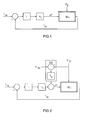
- FIG. 1 shows a fast analog controller for controlling the lamp current of a low-pressure discharge lamp according to the prior art.
- W / L designates a converter, in this case a half-bridge oscillator, with a connected low-pressure discharge lamp L.
- the signal line leading into block W / L is designated ⁇ T, which symbolizes that the switching times or the period duration of the converter operation are set here .
- I Li The outgoing from the block W / L signal line is denoted by I Li , which is symbolized that here the lamp current is measured by the lamp L.
- I Li shows that the measured "actual" lamp current I Li is compared via a comparator with a current setpoint I Ls .
- the setpoint deviation is fed to a fast analog integral control element designated I.
- the output signal of the integral control element I is multiplied by a certain factor k 1 and, as already mentioned, used to set the period T of the converter operation.
- the integral control I outputs a zero signal, the period remains the same. Therefore, the signal line to the block W / L is designated ⁇ T in terms of period change.
- FIG. 2 shows the invention in comparison to FIG. It will be for appropriate Parts using the same reference numerals. The following description focuses on the differences.
- the intermediate circuit voltage is here designated by the symbol U Zi .
- U Zs denotes a DC link voltage reference.
- the intermediate circuit voltage actual value (measured value) U Zi is compared via a comparator with the intermediate circuit voltage setpoint U Zs , multiplied by a constant k 2 and added to the already described with reference to Figure 1, multiplied by the constant k 1 output of the integral control I in the manner already described to influence the period of the converter operation.
- the constants k 1 and k 2 allow an adaptation of the behavior.
- the unit designated by the symbol SG from the comparator for comparing the intermediate circuit voltage actual value U Zi with the intermediate circuit voltage setpoint U Zs and the k 2 multiplication thus forms a disturbance variable connection to the control circuit, which otherwise corresponds in principle to FIG.
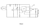
- the arrangement described in Figure 2 is part of a conventional electronic ballast for supplying a low-pressure discharge lamp L.
- a block diagram is shown in Figure 3.
- the intermediate circuit voltage U Zi is a conventional diode bridge rectifier with conventional filter elements to prevent the recovery of high frequency components in the network, in FIG 3 labeled FR generated.
- a power factor correction circuit is used, in this case a boost converter with the switching transistor T3, the inductance L1, the diode D1 and the storage capacitor C1 for the intermediate circuit voltage U Zi .
- the intermediate circuit voltage U Zi must be measured anyway, which is shown in Figure 3 by the tap on the unspecified voltage divider circuit. In this embodiment, this measurement is used simultaneously for the feedforward control illustrated in FIG.
- the feedforward control, the control loop, the control of the half-bridge oscillator W and the control of the boost converter are implemented together in software in a digital microcontroller .mu.C.
- the half-bridge oscillator W has the two switching transistors T1 and T2 of Figure 3 and supplies the lamp circuit connected in the usual way and not explained here with the lamp L at the center tap between the switching transistors T1 and T2 with a high-frequency oscillating supply voltage.
- the microcontroller .mu.C measures in the manner indicated in FIG. 3 the current through the lamp L and the current through the lower switching transistor T2 in order to correspondingly control the half-bridge oscillator W.
Landscapes
- Circuit Arrangements For Discharge Lamps (AREA)
Applications Claiming Priority (2)
| Application Number | Priority Date | Filing Date | Title |
|---|---|---|---|
| DE102004016945 | 2004-04-06 | ||
| DE102004016945A DE102004016945A1 (de) | 2004-04-06 | 2004-04-06 | EVG mit Regelschaltung und Störgrößenaufschaltung |
Publications (1)
| Publication Number | Publication Date |
|---|---|
| EP1585373A1 true EP1585373A1 (fr) | 2005-10-12 |
Family
ID=34895495
Family Applications (1)
| Application Number | Title | Priority Date | Filing Date |
|---|---|---|---|
| EP05004713A Withdrawn EP1585373A1 (fr) | 2004-04-06 | 2005-03-03 | Ballast électronique avec régulation de courant et contre-réaction positive d'une grandeur de perturbation |
Country Status (4)
| Country | Link |
|---|---|
| US (1) | US20050218824A1 (fr) |
| EP (1) | EP1585373A1 (fr) |
| CA (1) | CA2503752A1 (fr) |
| DE (1) | DE102004016945A1 (fr) |
Families Citing this family (2)
| Publication number | Priority date | Publication date | Assignee | Title |
|---|---|---|---|---|
| JP2007109661A (ja) * | 2005-10-12 | 2007-04-26 | Internatl Rectifier Corp | 8ピンによる力率改善およびバラスト制御のための集積回路 |
| DE102010039430A1 (de) * | 2010-08-18 | 2012-02-23 | Osram Ag | Elektronisches Vorschaltgerät und Verfahren zum Betreiben mindestens einer Entladungslampe |
Citations (6)
| Publication number | Priority date | Publication date | Assignee | Title |
|---|---|---|---|---|
| DE4110225A1 (de) * | 1991-03-28 | 1992-10-01 | Abb Patent Gmbh | Steuerverfahren und steueranordnung fuer einen wechselrichter |
| EP0596740A1 (fr) * | 1992-11-05 | 1994-05-11 | General Electric Company | Circuit et méthode d'alimentation d'une lampe à forte décharge par boucle de rétroaction |
| EP0605052A1 (fr) * | 1992-12-28 | 1994-07-06 | Koninklijke Philips Electronics N.V. | Ballast pour lampe à décharge |
| US20020067139A1 (en) * | 2000-12-05 | 2002-06-06 | Philips Elctronics North America Corporation | Electronic ballast with feed-forward control |
| WO2002098187A1 (fr) * | 2001-05-31 | 2002-12-05 | Koninklijke Philips Electronics N.V. | Dispositif de regulation de puissance et appareil et procede de regulation de la puissance fournie a une lampe a decharge |
| US20030057881A1 (en) * | 2001-09-04 | 2003-03-27 | Koninklijke Philips Electronics N.V. | Adaptive control for half-bridge universal lamp drivers |
Family Cites Families (5)
| Publication number | Priority date | Publication date | Assignee | Title |
|---|---|---|---|---|
| US3890537A (en) * | 1974-01-02 | 1975-06-17 | Gen Electric | Solid state chopper ballast for gaseous discharge lamps |
| US4327309A (en) * | 1980-06-23 | 1982-04-27 | General Electric Company | Fluorescent lamp power supply with low voltage lamp polarity reversal |
| US5371440A (en) * | 1993-12-28 | 1994-12-06 | Philips Electronics North America Corp. | High frequency miniature electronic ballast with low RFI |
| DE10051139A1 (de) * | 2000-10-16 | 2002-04-25 | Tridonic Bauelemente | Elektronisches Vorschaltgerät mit Vollbrückenschaltung |
| DE10106438A1 (de) * | 2001-02-09 | 2002-08-14 | Patent Treuhand Ges Fuer Elektrische Gluehlampen Mbh | Vorschaltgerät zum Betrieb von elektrischen Lampen |
-
2004
- 2004-04-06 DE DE102004016945A patent/DE102004016945A1/de not_active Withdrawn
-
2005
- 2005-03-03 EP EP05004713A patent/EP1585373A1/fr not_active Withdrawn
- 2005-04-04 CA CA002503752A patent/CA2503752A1/fr not_active Abandoned
- 2005-04-06 US US11/099,513 patent/US20050218824A1/en not_active Abandoned
Patent Citations (6)
| Publication number | Priority date | Publication date | Assignee | Title |
|---|---|---|---|---|
| DE4110225A1 (de) * | 1991-03-28 | 1992-10-01 | Abb Patent Gmbh | Steuerverfahren und steueranordnung fuer einen wechselrichter |
| EP0596740A1 (fr) * | 1992-11-05 | 1994-05-11 | General Electric Company | Circuit et méthode d'alimentation d'une lampe à forte décharge par boucle de rétroaction |
| EP0605052A1 (fr) * | 1992-12-28 | 1994-07-06 | Koninklijke Philips Electronics N.V. | Ballast pour lampe à décharge |
| US20020067139A1 (en) * | 2000-12-05 | 2002-06-06 | Philips Elctronics North America Corporation | Electronic ballast with feed-forward control |
| WO2002098187A1 (fr) * | 2001-05-31 | 2002-12-05 | Koninklijke Philips Electronics N.V. | Dispositif de regulation de puissance et appareil et procede de regulation de la puissance fournie a une lampe a decharge |
| US20030057881A1 (en) * | 2001-09-04 | 2003-03-27 | Koninklijke Philips Electronics N.V. | Adaptive control for half-bridge universal lamp drivers |
Also Published As
| Publication number | Publication date |
|---|---|
| CA2503752A1 (fr) | 2005-10-06 |
| US20050218824A1 (en) | 2005-10-06 |
| DE102004016945A1 (de) | 2005-10-27 |
Similar Documents
| Publication | Publication Date | Title |
|---|---|---|
| DE102004033354B4 (de) | Verfahren zur Ansteuerung eines Schalters in einem Hochsetzsteller und Ansteuerschaltung | |
| DE112006002495T5 (de) | Digitale Steuereinrichtung zur Leistungsfaktorkorrektur und diese aufweisende Wechselspannungs-zu-Gleichspannungsversorgung | |
| EP2188886B1 (fr) | Procédé de régulation d'un convertisseur à commutation | |
| DE102013106425B4 (de) | Schaltnetzteilvorrichtung und Verwendung einer solchen | |
| EP1872627B1 (fr) | Pfc numerique parametrable | |
| EP1227705A2 (fr) | Ballast pour lampes comprenant un convertisseur du type SEPIC | |
| DE19708791A1 (de) | Steuerschaltung und elektronisches Vorschaltgerät mit einer derartigen Steuerschaltung | |
| EP2512207B1 (fr) | Circuit d'excitation et procédé d'alimentation d'une DEL ainsi que moyen d'éclairage | |
| EP0641148B1 (fr) | Ballast électronique pour alimenter une charge, par exemple une lampe | |
| EP1585373A1 (fr) | Ballast électronique avec régulation de courant et contre-réaction positive d'une grandeur de perturbation | |
| DE2217023C3 (de) | Speiseschaltung für einen von einer ein- oder mehrphasigen Wechselstromquelle gespeisten Gleichstromverbraucher | |
| DE10120497B4 (de) | Elektronisches Vorschaltgerät | |
| EP1737279A2 (fr) | Dispositif et procédé d'élaboration d'une tension sinusoïdalement modulée en amplitude | |
| EP1696713B1 (fr) | Ballast électronique avec dispositif de mesure de courant pour lampe à décharge haute-pression | |
| EP3552458B1 (fr) | Agencement de circuits et procédé de fonctionnement d'un moyen d'éclairage | |
| EP0125385B1 (fr) | Dispositif pour générer des tensions ou courants continus réglés ou/et ajustables | |
| DE10045709A1 (de) | Elektronisches Vorschaltgerät | |
| EP3785492B1 (fr) | Circuit d'alimentation et procédé d'alimentation d'une charge électrique | |
| DE4140748C1 (en) | Converter supplying load in form of parallel oscillating circuit - has correction component assigned to regulating circuit for extinguishing time, also producing actual value for comparison with stipulated value | |
| EP2474206B1 (fr) | Correction de cosinus (phi) dans des ballasts à régulation du courant ou de la puissance pour des lampes | |
| DE10205552A1 (de) | Schaltungsanordnung und Ansteuerverfahren zur energieoptimalen Helligkeitssteuerung von Gasentladungslampen | |
| DE2030152A1 (de) | Schaltung zur Erzeugung einer stabilisierten Gleichspannung mittels einer Phasenanschnittsteuerung mit Thyristor | |
| DE10164242A1 (de) | Elektronisches Vorschaltgerät mit Strombegrenzung bei Leistungsreglung | |
| DE102004050110A1 (de) | Verfahren und Schaltungsanordnung zum Betreiben von Entladungslampen an ein- oder mehrphasigen Netzen mittels Vorschaltgerät | |
| EP1364737A1 (fr) | Source de courant pour le soudage à l'arc |
Legal Events
| Date | Code | Title | Description |
|---|---|---|---|
| PUAI | Public reference made under article 153(3) epc to a published international application that has entered the european phase |
Free format text: ORIGINAL CODE: 0009012 |
|
| AK | Designated contracting states |
Kind code of ref document: A1 Designated state(s): AT BE BG CH CY CZ DE DK EE ES FI FR GB GR HU IE IS IT LI LT LU MC NL PL PT RO SE SI SK TR |
|
| AX | Request for extension of the european patent |
Extension state: AL BA HR LV MK YU |
|
| 17P | Request for examination filed |
Effective date: 20051010 |
|
| AKX | Designation fees paid |
Designated state(s): AT BE BG CH CY CZ DE DK EE ES FI FR GB GR HU IE IS IT LI LT LU MC NL PL PT RO SE SI SK TR |
|
| STAA | Information on the status of an ep patent application or granted ep patent |
Free format text: STATUS: THE APPLICATION IS DEEMED TO BE WITHDRAWN |
|
| 18D | Application deemed to be withdrawn |
Effective date: 20060724 |