EP1585949B1 - Procede permettant de determiner les contraintes appliquees aux aubes d'une turbomachine en cours de fonctionnement et dispositif correspondant pour la mise en oeuvre dudit procede - Google Patents
Procede permettant de determiner les contraintes appliquees aux aubes d'une turbomachine en cours de fonctionnement et dispositif correspondant pour la mise en oeuvre dudit procede Download PDFInfo
- Publication number
- EP1585949B1 EP1585949B1 EP04702703A EP04702703A EP1585949B1 EP 1585949 B1 EP1585949 B1 EP 1585949B1 EP 04702703 A EP04702703 A EP 04702703A EP 04702703 A EP04702703 A EP 04702703A EP 1585949 B1 EP1585949 B1 EP 1585949B1
- Authority
- EP
- European Patent Office
- Prior art keywords
- electromagnetic wave
- turbine
- blades
- accordance
- stress
- Prior art date
- Legal status (The legal status is an assumption and is not a legal conclusion. Google has not performed a legal analysis and makes no representation as to the accuracy of the status listed.)
- Expired - Lifetime
Links
- 238000000034 method Methods 0.000 title claims description 36
- 238000011156 evaluation Methods 0.000 claims description 21
- 238000012544 monitoring process Methods 0.000 description 10
- 230000035882 stress Effects 0.000 description 8
- 238000012423 maintenance Methods 0.000 description 7
- 230000005540 biological transmission Effects 0.000 description 6
- 239000011248 coating agent Substances 0.000 description 6
- 238000000576 coating method Methods 0.000 description 6
- 230000010355 oscillation Effects 0.000 description 6
- 230000005855 radiation Effects 0.000 description 5
- 230000000694 effects Effects 0.000 description 4
- 230000002349 favourable effect Effects 0.000 description 4
- 230000008878 coupling Effects 0.000 description 3
- 238000010168 coupling process Methods 0.000 description 3
- 238000005859 coupling reaction Methods 0.000 description 3
- 238000010586 diagram Methods 0.000 description 3
- 238000005259 measurement Methods 0.000 description 3
- 230000008901 benefit Effects 0.000 description 2
- 230000008859 change Effects 0.000 description 2
- 238000010276 construction Methods 0.000 description 2
- 230000009977 dual effect Effects 0.000 description 2
- 230000003595 spectral effect Effects 0.000 description 2
- 230000032683 aging Effects 0.000 description 1
- 230000004888 barrier function Effects 0.000 description 1
- 230000015572 biosynthetic process Effects 0.000 description 1
- 238000002485 combustion reaction Methods 0.000 description 1
- 238000004891 communication Methods 0.000 description 1
- 239000004020 conductor Substances 0.000 description 1
- 238000005336 cracking Methods 0.000 description 1
- 230000007547 defect Effects 0.000 description 1
- 238000011161 development Methods 0.000 description 1
- 230000018109 developmental process Effects 0.000 description 1
- 230000005670 electromagnetic radiation Effects 0.000 description 1
- 238000005265 energy consumption Methods 0.000 description 1
- 239000002184 metal Substances 0.000 description 1
- 230000000704 physical effect Effects 0.000 description 1
- 230000008439 repair process Effects 0.000 description 1
- 238000001228 spectrum Methods 0.000 description 1
- 238000012360 testing method Methods 0.000 description 1
Images



Classifications
-
- G—PHYSICS
- G01—MEASURING; TESTING
- G01H—MEASUREMENT OF MECHANICAL VIBRATIONS OR ULTRASONIC, SONIC OR INFRASONIC WAVES
- G01H9/00—Measuring mechanical vibrations or ultrasonic, sonic or infrasonic waves by using radiation-sensitive means, e.g. optical means
-
- F—MECHANICAL ENGINEERING; LIGHTING; HEATING; WEAPONS; BLASTING
- F01—MACHINES OR ENGINES IN GENERAL; ENGINE PLANTS IN GENERAL; STEAM ENGINES
- F01D—NON-POSITIVE DISPLACEMENT MACHINES OR ENGINES, e.g. STEAM TURBINES
- F01D21/00—Shutting-down of machines or engines, e.g. in emergency; Regulating, controlling, or safety means not otherwise provided for
- F01D21/003—Arrangements for testing or measuring
-
- F—MECHANICAL ENGINEERING; LIGHTING; HEATING; WEAPONS; BLASTING
- F01—MACHINES OR ENGINES IN GENERAL; ENGINE PLANTS IN GENERAL; STEAM ENGINES
- F01D—NON-POSITIVE DISPLACEMENT MACHINES OR ENGINES, e.g. STEAM TURBINES
- F01D21/00—Shutting-down of machines or engines, e.g. in emergency; Regulating, controlling, or safety means not otherwise provided for
- F01D21/14—Shutting-down of machines or engines, e.g. in emergency; Regulating, controlling, or safety means not otherwise provided for responsive to other specific conditions
-
- G—PHYSICS
- G01—MEASURING; TESTING
- G01H—MEASUREMENT OF MECHANICAL VIBRATIONS OR ULTRASONIC, SONIC OR INFRASONIC WAVES
- G01H1/00—Measuring characteristics of vibrations in solids by using direct conduction to the detector
- G01H1/003—Measuring characteristics of vibrations in solids by using direct conduction to the detector of rotating machines
- G01H1/006—Measuring characteristics of vibrations in solids by using direct conduction to the detector of rotating machines of the rotor of turbo machines
-
- G—PHYSICS
- G01—MEASURING; TESTING
- G01L—MEASURING FORCE, STRESS, TORQUE, WORK, MECHANICAL POWER, MECHANICAL EFFICIENCY, OR FLUID PRESSURE
- G01L1/00—Measuring force or stress, in general
- G01L1/25—Measuring force or stress, in general using wave or particle radiation, e.g. X-rays, microwaves, neutrons
-
- G—PHYSICS
- G01—MEASURING; TESTING
- G01M—TESTING STATIC OR DYNAMIC BALANCE OF MACHINES OR STRUCTURES; TESTING OF STRUCTURES OR APPARATUS, NOT OTHERWISE PROVIDED FOR
- G01M13/00—Testing of machine parts
-
- G—PHYSICS
- G01—MEASURING; TESTING
- G01S—RADIO DIRECTION-FINDING; RADIO NAVIGATION; DETERMINING DISTANCE OR VELOCITY BY USE OF RADIO WAVES; LOCATING OR PRESENCE-DETECTING BY USE OF THE REFLECTION OR RERADIATION OF RADIO WAVES; ANALOGOUS ARRANGEMENTS USING OTHER WAVES
- G01S13/00—Systems using the reflection or reradiation of radio waves, e.g. radar systems; Analogous systems using reflection or reradiation of waves whose nature or wavelength is irrelevant or unspecified
- G01S13/02—Systems using reflection of radio waves, e.g. primary radar systems; Analogous systems
- G01S13/50—Systems of measurement based on relative movement of target
-
- G—PHYSICS
- G01—MEASURING; TESTING
- G01S—RADIO DIRECTION-FINDING; RADIO NAVIGATION; DETERMINING DISTANCE OR VELOCITY BY USE OF RADIO WAVES; LOCATING OR PRESENCE-DETECTING BY USE OF THE REFLECTION OR RERADIATION OF RADIO WAVES; ANALOGOUS ARRANGEMENTS USING OTHER WAVES
- G01S13/00—Systems using the reflection or reradiation of radio waves, e.g. radar systems; Analogous systems using reflection or reradiation of waves whose nature or wavelength is irrelevant or unspecified
- G01S13/88—Radar or analogous systems specially adapted for specific applications
-
- F—MECHANICAL ENGINEERING; LIGHTING; HEATING; WEAPONS; BLASTING
- F05—INDEXING SCHEMES RELATING TO ENGINES OR PUMPS IN VARIOUS SUBCLASSES OF CLASSES F01-F04
- F05D—INDEXING SCHEME FOR ASPECTS RELATING TO NON-POSITIVE-DISPLACEMENT MACHINES OR ENGINES, GAS-TURBINES OR JET-PROPULSION PLANTS
- F05D2300/00—Materials; Properties thereof
- F05D2300/60—Properties or characteristics given to material by treatment or manufacturing
- F05D2300/611—Coating
Definitions
- the present invention relates to methods for determining the load of in a turbomachine with arranged on a rotatably mounted in a housing rotor shaft blades. Furthermore, the invention relates to a method for determining the load of non-rotatably arranged in a turbomachine with a housing guide vanes, and an apparatus for performing the method.
- Turbomachines such as steam or gas turbines, are used as heat-power machines in the art to convert an energy stored in a gas stream into a mechanical energy, in particular a rotational movement.
- the gas inlet temperatures are selected from the combustion chamber in the flow channel of the gas turbine as high as possible.
- gas inlet temperatures are for example at 1200 ° C.
- blades and vanes always get into mechanical vibrations. If the vibrations are too pronounced, cracking of the blades can occur, which in extreme cases can cause the blades to break off. In particular, broken blade parts may pierce metal walls due to their high kinetic energy, e.g. the housing wall of the turbine. In addition to the damage to the turbine, this also poses a danger to the people in the vicinity.
- a microwave conductor tube is positioned in the vicinity of a rotating row of blades of a turbine in such a way that upon rotation of the rotor shaft, the blade tips pass through the opening of the waveguide tube.
- the waveguide tube then sends a continuous wave of microwave energy to the rotating blade row.
- a reflected wave is created which forms a standing wave along with the transmitted wave. This collapses as soon as the blade tip continues to run and does not build up until the subsequent blade tip appears in front of the hole.
- Each passage of a single bucket tip through the continuous wave web produces a signal in time with the bucket tips passing the port.
- Deviations in the regularity of the clock provide information about the vibration state of the blade.
- the intensity of the reflected wave is measured, which also changes in time with the passing blade tips.
- the signal evaluation happens analogous to the embodiment described above.
- this known device it is only possible to obtain information about the vibration state to a limited extent. Since the emitted wave is reflected at the blade tips, only vibration modes are detected which are particularly pronounced at the blade ends. Modes with special characteristics in the area between rotor shaft and blade tip can not be detected with this device.
- this disclosed blade vibration monitoring apparatus can not be used.
- the invention proposes a method for determining the loading of in a turbomachine with arranged on a rotatably mounted in a housing rotor shaft blades, wherein means for generating at least one electromagnetic wave at least one electromagnetic wave in the flow channel in a region of Rotor blades is emitted which at least partially reflects at least one electromagnetic wave of at least one blade, the reflected part of the at least one electromagnetic wave received by means for receiving and from one of the received at least one electromagnetic wave signal corresponding to the demand of the blades is determined.
- the reflected portion of the at least one electromagnetic wave contains information about the state of stress or the degree or extent of the impact of the blades on the desired state, which can be determined by evaluating the received signal.
- the amplitude and / or phase and / or the spectral distribution of the signal can be considered as parameters.
- a method for determining the load of in a turbomachine with a housing rotatably arranged vanes wherein by means for generating at least one electromagnetic At least one electromagnetic wave is emitted in a flow channel in a region of the guide vanes, which at least partially reflects at least one electromagnetic wave of at least one vane, the reflected part of the at least one electromagnetic wave received by means for receiving and from one of the at least one received electromagnetic Wave corresponding signal the load of the vanes is determined.
- a method is further proposed to determine the surface quality of the blades as a measure of the stress. For the first time, it is thus possible to detect a corresponding condition of blades not only without disassembly of the turbine, but also to monitor during operation of the turbine.
- a maintenance of a turbine can advantageously be carried out when the load is definitely reached a limit of wear with respect to the surface quality.
- the maintenance intervals can be extended to the actual requirements.
- the costs caused by the maintenance of the turbine, in particular the service life can be significantly reduced.
- the reflected portions may be received at different locations on the circumference of the flow channel to thereby obtain additional and / or more accurate information about the condition of the surface finish.
- the method can of course also be used dual to determine a surface quality of vanes arranged in a turbomachine, however, the means for generating at least one electromagnetic Shaft and are arranged to receive on the rotatably mounted rotor shaft.
- non-rotating elements of the turbomachine can thus be monitored with regard to their surface quality.
- means distributed over the circumference of the turbomachine for emitting at least one electromagnetic wave can be used, with an arrangement being able to be provided as required.
- means may be provided for receiving to receive reflected electromagnetic waves.
- it may be provided, for example, to operate the arrangement in pulse mode and / or in time-division multiplex mode.
- a means for emitting at least one electromagnetic wave is simultaneously also used for the reception, wherein this is arranged on the housing in the region of the guide vanes to be monitored.
- At least one adapted to the respective surface shape electromagnetic wave is used with an adapted wavelength.
- the effects of the damage on the at least one electromagnetic wave are particularly favorable, for example, to achieve a high signal level for the evaluation unit, from which the surface quality is determined.
- the means for generating at least one electromagnetic wave is used for the reception of at least one electromagnetic wave.
- Components as well as assembly and construction costs on the turbine can be reduced.
- an antenna can be used for both transmission and reception.
- the surface quality is determined from an intensity of the at least one received electromagnetic wave.
- an evaluation of the signal can be achieved advantageously with simple and inexpensive means.
- other suitable wavelengths may be used, such as millimeter waves and the like.
- a method is also proposed, as a measure of the stress to determine the vibration state of the blades. It is thus possible, in addition to the vibration states that vibrate the blade tips, also determine vibration states whose modes are particularly pronounced in the central region of the blade, ie between blade tip and rotor shaft. This has the advantage that the information about the vibration state of the blades is more comprehensive and accurate than in the prior art. Damage due to modes that are particularly pronounced in the central area of the blades can be avoided by timely intervention.
- the method can also be used dual for determining a vibration state of arranged in a turbomachine vanes, wherein the means for generating at least one electromagnetic wave and for receiving can also be arranged on the rotatably mounted rotor shaft.
- the invention also a method for determining the vibration state of in a turbomachine proposed with a housing rotationally fixed vanes, wherein by means for generating at least one electromagnetic wave at least one electromagnetic wave is emitted in a flow channel in a region of the vanes, the at least one electromagnetic wave of at least one vane at least partially reflected, the reflected part of the at least receive an electromagnetic wave by means for receiving and from one of the at least one received electromagnetic wave signal corresponding to the vibration state of the guide vanes is determined.
- non-rotating elements of the turbomachine can thus be monitored with regard to their vibration state.
- means distributed over the circumference of the turbomachine for emitting at least one electromagnetic wave can be used, with an arrangement being able to be provided as required.
- means may be provided for receiving to receive reflected electromagnetic waves.
- it may be provided, for example, to operate the arrangement in pulse mode and / or in time-division multiplex mode.
- a means for emitting at least one electromagnetic wave is simultaneously also used for the reception, wherein this is arranged on the housing in the region of the guide vanes to be monitored.
- an at least one electromagnetic wave with an adapted wavelength adapted to the respective surface form is used. So it can be advantageously achieved that the effects of the vibrations on the at least one electromagnetic wave are particularly favorable, for example, to achieve a high signal level for the evaluation unit, from which the vibration state is determined.
- At least one radar wave is used as at least one electromagnetic wave.
- recourse can be had to known means for generating and transmitting radar waves. Effort and costs can be further reduced.
- an adjustment with respect to the oscillation frequency and / or the damage of the blades can be achieved, so that a favorable signal level for monitoring the oscillation state and / or the surface quality can be achieved.
- the means for generating at least one electromagnetic wave is used for the reception of at least one electromagnetic wave.
- Components as well as assembly and construction costs on the turbine can be reduced.
- a radar antenna can be used for both transmission and reception.
- the vibration state of the blades is determined from a frequency comparison of the at least one emitted and the at least one received electromagnetic wave.
- an evaluation of the signal can be achieved advantageously with simple and inexpensive means.
- other suitable wavelengths may be used, such as millimeter waves and the like.
- the surface quality and the vibration state of the blades are determined simultaneously as a measure of the stress.
- the time and Simultaneous measurement also provides a more comprehensive overview of the load on the blades, allowing for faster intervention in case of emerging damage.
- the invention further provides an apparatus for carrying out the method according to the invention, which comprises means for generating an electrical oscillation, means for generating at least one electromagnetic wave from the oscillation, means for receiving at least one electromagnetic wave and an evaluation unit for evaluating one of the at least one receivable electromagnetic wave corresponding signal has.
- the means for generating at least one electromagnetic wave and for receiving in a flow channel of the turbomachine are arranged. These may each be formed by antennas which are suitable for generating and transmitting the electromagnetic waves and for generating a corresponding signal.
- the means for generating an electrical oscillation may, for example, be formed by an electronic oscillator, which is in operative connection with the antenna for generating at least one electromagnetic wave.
- the means for receiving at least one electromagnetic wave is preferably in operative connection with an evaluation unit which is able to determine information about the vibration state and / or the surface quality of the blades from the signal supplied by the means for reception.
- the means for generating at least one electromagnetic wave both for transmitting and for receiving at least one electromagnetic wave is suitable.
- the number of components can be further reduced in this way.
- the means for generating at least one electromagnetic wave via a coupling means with the means for generating a vibration in operative connection.
- One of the least a received electromagnetic wave corresponding signal is supplied via the coupling means of the evaluation unit.
- a plurality of coupling means and antennas which, for example, are connected in parallel with a plurality of associated evaluation units or also with, for example, an evaluation unit in time-division multiplex.
- the means for generating at least one electromagnetic wave is at least one radar antenna.
- the radar antenna can be compact and have small dimensions.
- the radar antenna is suitable both for emitting at least one radar wave and for receiving at least one radar wave.
- it may, for example, be connected to a circulator, via which a vibration can be fed to the antenna, wherein at the same time a received signal supplied by the radar antenna can be transmitted to an evaluation unit.
- a method according to the Doppler principle can be used, in which the reception wavelength deviates from the transmission wavelength.
- electronic means a simultaneous operation of the transmission and the reception of electromagnetic waves can be achieved.
- a wave pulse can be emitted, wherein in the pulse pauses the means for generating at least one electromagnetic wave is switched to receive. Energy and effort to generate the at least one electromagnetic wave can be saved.
- the means for generating at least one electromagnetic wave in the turbomachine in particular a gas turbine
- the means for generating at least one electromagnetic wave in the turbomachine is arranged.
- a cost-effective monitoring of the blades can be achieved with the device according to the invention, which in particular expensive downtime due to maintenance and repair measures can be further reduced.
- a Increase the availability of a gas turbine equipped with a power supply can be achieved.
- the device according to the invention can be designed such that the effects on the gas flow in the flow channel of the turbomachine are kept substantially low.
- FIG. 1 shows a prior art gas turbine 1, which is designed for a high gas inlet temperature of approximately 1200 ° C.
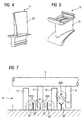
- the gas turbine 1 has arranged on a rotatably mounted in a housing 2 rotor shaft 3 blades 4. Further, rotatably connected guide vanes 11 are provided with the housing 2 ( Figure 4, Figure 5).
- the rotor blades 4 and the guide vanes 11 are each provided in particular with a surface coating 12, 13, to keep the physical stresses in the flow channel 6 of the gas turbine 1 stand.
- the turbine 1 is equipped with a device according to the invention, which has an antenna 8, in particular a radar antenna, which projects into the flow channel 6 of the gas turbine 1.
- the radar antenna 8 is arranged in the region of the rotor blades 4 to be monitored, in particular between two blade rows.
- the radar antenna 8 serves as a means for emitting at least one electromagnetic wave as well as a means for receiving the at least one electromagnetic wave.
- the radar antenna 8 is in communication with a circulator 16.
- the device according to the invention also has a high-frequency generator 14, which is connected via an amplifier 15 with the circulator 16 in operative connection.
- the circulator 16 is at the same time connected to a receiving amplifier 17 and to a mixer 18, which in turn is connected to the high-frequency generator 14 at the same time.
- An output of the mixer 18 is coupled to the evaluation unit 19 ( Figure 2).
- the principle of a Doppler radar is used.
- the reception wavelength in the reflected part 32 of the at least one electromagnetic wave is shifted with respect to the transmitted wavelength according to the known physical effects, and the antenna 8 generates a corresponding signal.
- An electronic high frequency generator 14 generates a high frequency having a fixed, predeterminable wavelength, which preferably corresponds to one of the frequencies f 0 given in Table 1.
- Table 1 f 0 / GHz 2.4 5.8 24 61 122 245 f D / kHz 6032 14577 60.32 153.3 306.6 459.9
- the high frequency is supplied to an amplifier 15, which in turn feeds the amplified high frequency via the circulator 16 of the antenna 8.
- the antenna 8 generates from the supplied high-frequency energy at least one corresponding radar wave 31 and emits these according to their radiation characteristics.
- the moving past the radar antenna 8 blades 4 reflect a part 32 of the radar back to the antenna 8, where they cause due to their relative movement to the antenna 8, composed of rotational movement and vibration, a wavelength change.
- f o is the frequency of the at least one emitted wave 31
- v (t) the relative velocities of the surfaces of the blades 4 and vanes 11 reflecting the at least one electromagnetic wave 31 with respect to the antenna 8
- c o the propagation velocity of the at least one electromagnetic wave 31 , 32.
- the at least one reflected electromagnetic wave 32 is transformed back into an electrical signal via the antenna 8, which is supplied to the circulator 16.
- the circulator 16 now separates the received signal from the transmitted signal and supplies it to the receiving amplifier 17. From the receiving amplifier 17, the signal passes to a mixer 18 in which it is mixed with a signal corresponding to the high frequency of the high-frequency generator 14. The phase angles of the high frequency from the high frequency generator 14 and the signal from the receiving amplifier 17 are taken into account accordingly.
- the output signal of the mixer 18 supplies a signal with the difference frequency between the receiving frequency and the emitted high frequency.
- the evaluation result determined is reported to the monitoring point via display units or message units (not shown) or forwarded to a control center.
- the evaluation unit can also be equipped with a comparison function, with which the achievement of a predefinable threshold value can be determined. For example, when the threshold value is reached, a message can be automatically output that maintenance of the turbine 1 is to be carried out.
- the signal intensity can be used for this purpose.
- FIG. 7 shows exemplary embodiments and arrangements of various antennas 81, 82 and 83, each with associated radiation characteristics 810, 820 and 830.
- the antennas 81, 82 and 83 are arranged in the flow channel 6 in the region of the blades to be monitored 4 and / or vanes 11 between the blade rows.
- An embodiment is suitable as a rod antenna or as a coaxial antenna, in particular as a coaxial dipole antenna. However, other antenna shapes are also conceivable.
- the radiation characteristic may be symmetrical, as in the antennas 81 and 83, but asymmetric, as in the antenna 82 may be formed.
- the moving parts in this case the moving blades 4
- the Doppler shift caused only by the vibration of the relative to the antennas 81, 82 or 83 fixed parts, in this case the guide vanes 11, determine.
- the Doppler shift is caused only by the oscillation movement but not by a relative movement due to the rotational movement.
- the antennas 81, 82 and 83 can also be operated passively in addition to the active mode of operation described here, ie with targeted emission of at least one electromagnetic wave 31 for the purpose of detecting the moving blades 4 and / or the guide vanes 11.
- the antennas 81, 82 and 83 emit no transmit radiation, but receive only electromagnetic radiation that is present in the flow channel 6, in particular due to defects on the blades 4 and / or on the vanes 11.
- the antennas 81, 82 and 83 are then determined exclusively for "listening".
- the guide vanes 11 and / or the rotor blades 4 of a gas turbine 1 are monitored by means of pulsed radar.
- FIG. 6 shows a block diagram of such an embodiment for detecting the guide vanes 11.
- Transmitting antennas 5 are arranged distributed over the circumference of the flow channel 6 of the gas turbine 1 in order to emit at least one electromagnetic wave 31 in the area of the guide vanes 11 of the gas turbine 1.
- the antennas 5 are connected to a high frequency generator 9, which supplies each antenna with high frequency.
- the high-frequency generator 9 is a pulse generator which generates short high-frequency pulses with a predefinable pulse-pause ratio and distributes them in time-multiplexed manner to the antennas 5 connected to them.
- receiving antennas 7 for receiving reflected electromagnetic waves 32 are arranged.
- the receiving antennas 7 are connected to a multiplexer 20, which also has a function as a receiving amplifier.
- the multiplexer 20 it is achieved via the multiplexer 20 that an antenna 7 is connected to the evaluation unit 19 in a time-discrete manner.
- the evaluation unit 19 receives high frequency from the high frequency generator 9.
- the evaluation unit 19 receives via a line 21 a channel selection signal, which transmits information about the selected antenna 7 to the evaluation unit 19.
- the vane monitoring shown here is operated in pulsed mode, so that the energy consumption can be kept low overall.
- the components for generating at least one electromagnetic wave can be designed overall for a lower load with respect to the thermal.
- the present invention is not limited to the embodiment. Also included in the scope is that several radar antennas are provided for transmission and / or reception, for example to achieve a redundancy of the measurement or even a higher accuracy.
- the present invention provides a simultaneous measurement of the vibration condition and the surface finish of said blades.
- the present invention is not limited to the use of only a single electromagnetic wave 31, 32. Of course, it also includes the transmission and reception of multiple electromagnetic waves or wave spectra.
Landscapes
- Engineering & Computer Science (AREA)
- Physics & Mathematics (AREA)
- Radar, Positioning & Navigation (AREA)
- Remote Sensing (AREA)
- General Physics & Mathematics (AREA)
- General Engineering & Computer Science (AREA)
- Mechanical Engineering (AREA)
- Computer Networks & Wireless Communication (AREA)
- Health & Medical Sciences (AREA)
- Toxicology (AREA)
- Electromagnetism (AREA)
- Turbine Rotor Nozzle Sealing (AREA)
- Investigating Or Analyzing Materials By The Use Of Ultrasonic Waves (AREA)
- Radar Systems Or Details Thereof (AREA)
- Testing Of Devices, Machine Parts, Or Other Structures Thereof (AREA)
Claims (17)
- Procédé de détermination des contraintes appliquées aux aubes (4) mobiles disposées dans une turbomachine (1) ayant un arbre (3) de rotor monté tournant dans un carter (2) dans lequel on émet par des moyens (5, 8, 81, 82, 83) de production d'au moins une onde électromagnétique disposés entre des rangées d'aubes mobiles au moins une onde (31) électromagnétique dans un canal (6) d'écoulement dans une zone des aubes (4) mobiles comprise entre les rangées d'aubes mobiles, on réfléchit au moins en partie la au moins une onde (31) électromagnétique par au moins une aube (4) mobile, on reçoit la partie (32) réfléchie de la au moins une onde électromagnétique par des moyens (7, 8, 81, 82, 83) de réception disposés entre les rangées d'aubes mobiles et on détermine les contraintes appliquées aux aubes (4) mobiles à partir d'un signal correspondant à la au moins une onde électromagnétique reçue.
- Procédé de détermination des contraintes appliquées à des aubes (11) directrices montées sans tourner sur un carter (2) dans une turbomachine (1) dans lequel on émet par des moyens (5, 8, 81, 82, 83) de production d'au moins une onde électromagnétique disposés entre des rangées d'aubes directrices au moins une onde (31) électromagnétique dans un canal (6) d'écoulement dans une zone des aubes (11) directrices comprise entre les rangées d'aubes directrices, on réfléchit au moins en partie la au moins une onde (31) électromagnétique par au moins une aube (11) directrice, on reçoit la partie (32) réfléchie de la au moins une onde électromagnétique par des moyens (7, 8, 81, 82, 83) de réception disposés entre les rangées d'aubes directrices et on détermine les contraintes appliquées aux aubes (11) directrices à partir d'un signal correspondant à la au moins une onde électromagnétique reçue.
- Procédé suivant la revendication 1 et 2, caractérisé en ce que l'on détermine sur l'arbre (3) rotorique de la turbomachine munie des aubes (4) mobiles et des aubes (11) directrices tant les contraintes appliquées aux aubes (4) mobiles que les contraintes appliquées aux aubes (11) directrices, dans lequel on émet par des moyens (5, 8, 81, 82, 83) disposés entre les rangées d'aubes mobiles et les rangées d'aubes directrices et de production d'au moins une onde électromagnétique la au moins une onde (31) électromagnétique dans le canal (6) d'écoulement dans la zone des aubes (4) mobiles et des aubes (11) directrices entre les rangées d'aubes mobiles et les rangées d'aubes directrices, et
on reçoit la partie (32) réfléchie de la au moins une onde électromagnétique par des moyens (7, 8, 81, 82, 83) de réception disposés entre les rangées d'aubes mobiles et les rangées d'aubes directrices. - Procédé suivant l'une des revendications 1 à 3, caractérisé en ce que l'on détermine comme mesure des contraintes appliquées la qualité de surface des aubes.
- Procédé suivant la revendication 4, caractérisé en ce qu'en fonction des structures de surface à déterminer on utilise au moins une onde (31) électromagnétique adaptée à la forme de surface respective et ayant une longueur d'onde adaptée.
- Procédé suivant l'une des revendications 1 à 5, caractérisé en ce que l'on utilise le moyen (8) de production d'au moins une onde électromagnétique pour la réception d'au moins une onde (32) électromagnétique.
- Procédé suivant l'une des revendications 4 à 6, caractérisé en ce que l'on détermine la qualité de surface des aubes à partir d'une intensité de la au moins une onde (32) électromagnétique reçue.
- Procédé suivant l'une des revendications 1 à 3, caractérisé en ce que l'on détermine comme mesure des contraintes appliquées l'état d'oscillation des aubes.
- Procédé suivant la revendication 8, caractérisé en ce que l'on utilise au moins une onde (31) électromagnétique adaptée à la forme respective de surface et ayant une longueur d'onde adaptée.
- Procédé suivant la revendication 1 à 9, caractérisé en ce que l'on utilise au moins une onde (31) radar comme onde électromagnétique.
- Procédé suivant l'une des revendications 8 à 10, caractérisé en ce que l'on utilise des moyens (8) de production d'au moins une onde électromagnétique pour la réception d'au moins une onde (32) électromagnétique.
- Procédé suivant l'une des revendications 8 à 11, caractérisé en ce que l'on détermine l'état d'oscillation des aubes à partir d'une comparaison de fréquence entre la au moins une onde (32) électromagnétique émise et la au moins une onde (32) électromagnétique reçue.
- Procédé suivant l'une des revendications précédentes, caractérisé en ce que l'on détermine simultanément la qualité de surface et l'état d'oscillation des aubes comme mesures des contraintes appliquées.
- Turbomachine (1) comprenant des aubes (4) mobiles disposées sur un arbre (3) rotorique monté tournant dans un carter (2), des aubes (11) directrices disposées sans pouvoir tourner et un dispositif pour la mise en oeuvre du procédé suivant l'une des revendications précédentes comprenant des moyens de production d'une oscillation électrique, des moyens (5, 8) disposés entre les rangées d'aubes mobiles et/ou les rangées d'aubes directrices de production d'au moins une onde (31) électromagnétique à partir de l'oscillation, des moyens (7, 8) disposés entre les rangées d'aubes mobiles et/ou les rangées d'aubes directrices de réception d'au moins une onde (32) électromagnétique et une unité (10) d'exploitation de la au moins une onde (32) électromagnétique qui peut être reçue.
- Turbomachine suivant la revendication 14, caractérisée en ce que le moyen (8) de production d'au moins une onde électromagnétique est approprié à la fois pour émettre et pour recevoir au moins une onde (31, 32) électromagnétique.
- Turbomachine suivant la revendication 14 ou 15, caractérisée en ce que le moyen (5, 8) de production d'au moins une onde (31) électromagnétique est une antenne radar.
- Turbomachine suivant l'une des revendications 14 à 16, caractérisée en ce que le moyen (5, 8) de production d'au moins une onde (31) électromagnétique est disposé dans le canal (6) d'écoulement de la turbomachine (1) qui est notamment une turbine à gaz.
Applications Claiming Priority (5)
| Application Number | Priority Date | Filing Date | Title |
|---|---|---|---|
| DE10302714 | 2003-01-23 | ||
| DE10302714 | 2003-01-23 | ||
| DE10356513 | 2003-12-03 | ||
| DE10356513 | 2003-12-03 | ||
| PCT/EP2004/000324 WO2004065918A2 (fr) | 2003-01-23 | 2004-01-16 | Procede permettant de determiner la contrainte appliquee aux aubes d'une turbomachine en cours de fonctionnement et dispositif correspondant pour la mise en oeuvre dudit procede |
Publications (2)
| Publication Number | Publication Date |
|---|---|
| EP1585949A2 EP1585949A2 (fr) | 2005-10-19 |
| EP1585949B1 true EP1585949B1 (fr) | 2007-05-02 |
Family
ID=32683499
Family Applications (1)
| Application Number | Title | Priority Date | Filing Date |
|---|---|---|---|
| EP04702703A Expired - Lifetime EP1585949B1 (fr) | 2003-01-23 | 2004-01-16 | Procede permettant de determiner les contraintes appliquees aux aubes d'une turbomachine en cours de fonctionnement et dispositif correspondant pour la mise en oeuvre dudit procede |
Country Status (5)
| Country | Link |
|---|---|
| US (1) | US7373823B2 (fr) |
| EP (1) | EP1585949B1 (fr) |
| DE (2) | DE10359930A1 (fr) |
| ES (1) | ES2283971T3 (fr) |
| WO (1) | WO2004065918A2 (fr) |
Cited By (1)
| Publication number | Priority date | Publication date | Assignee | Title |
|---|---|---|---|---|
| EP1751581B1 (fr) * | 2004-05-27 | 2014-01-15 | Siemens Aktiengesellschaft | Systeme de detection a radar doppler utilise dans la surveillance des composants d'un turbogenerateur |
Families Citing this family (29)
| Publication number | Priority date | Publication date | Assignee | Title |
|---|---|---|---|---|
| DE102004050906B3 (de) * | 2004-10-19 | 2006-04-20 | Siemens Ag | Verfahren zum Ermitteln der Temperatur einer Oberflächenbeschichtung von Schaufeln einer Strömungsmaschine während des Betriebs sowie entsprechende Vorrichtung zur Durchführung des Verfahrens |
| DE102005032649A1 (de) * | 2005-07-13 | 2007-01-25 | Hella Kgaa Hueck & Co. | Vorrichtung zum Simulieren eines beweglichen Radarziels |
| JP4847527B2 (ja) * | 2005-08-17 | 2011-12-28 | シーメンス アクチエンゲゼルシヤフト | 流体機械の少なくとも1個の翼のtbc被覆の層厚を検出する方法と、この方法を実施するためのtbc被覆層厚測定装置と、この方法およびtbc被覆層厚測定装置の利用 |
| US7533575B2 (en) * | 2006-02-03 | 2009-05-19 | Jentek Sensors, Inc. | Quasistatic magnetic and electric field stress/strain gages |
| DE102006033461A1 (de) * | 2006-07-19 | 2008-01-31 | Siemens Ag | Radialspaltmessung an Turbinen |
| KR100803127B1 (ko) * | 2006-12-06 | 2008-02-14 | 엘지전자 주식회사 | 모터 전원장치 및 이를 포함하는 모터 |
| US7825669B2 (en) * | 2007-03-29 | 2010-11-02 | Hamilton Sundstrand Corporation | Microwave position sensing for a turbo machine |
| US20100095740A1 (en) * | 2007-12-07 | 2010-04-22 | The Ohio State University Research Foundation | Determining physical properties of structural members in multi-path clutter environments |
| US8342027B2 (en) | 2007-12-07 | 2013-01-01 | The Ohio State University | Determining physical properties of objects or fluids in multi-path clutter environments |
| US7941281B2 (en) * | 2008-12-22 | 2011-05-10 | General Electric Company | System and method for rotor blade health monitoring |
| DE102009009384B4 (de) * | 2009-02-18 | 2010-11-04 | Siemens Aktiengesellschaft | Detektion von Druckschwankungen in einem heißen Medium auf Basis von Millimeterwellen |
| DE102010003347B4 (de) | 2009-05-20 | 2021-08-05 | Robert Bosch Gmbh | Verfahren und Vorrichtung zum Bestimmen einer oder mehrerer Drehzahlen einer Aufladeeinrichtung, insbesondere für einen Verbrennungsmotor |
| US8606541B2 (en) * | 2009-06-12 | 2013-12-10 | Mechanical Solutions, Inc. | Combined amplitude and frequency measurements for non-contacting turbomachinery blade vibration |
| DE102010006334A1 (de) * | 2010-01-29 | 2011-08-04 | pro-micron GmbH & Co. KG, 87600 | System und Verfahren zur Störunterdrückung bei frequenzmodulierten Radarsystemen |
| WO2012129377A1 (fr) * | 2011-03-23 | 2012-09-27 | Meggitt Sa | Mesures de rotors à pales |
| US20130003071A1 (en) * | 2011-06-30 | 2013-01-03 | Catch the Wind, Inc. | System and Method of In Situ Wind Turbine Blade Monitoring |
| US9188477B2 (en) * | 2011-08-18 | 2015-11-17 | Linear Technology Corporation | Radar system and method for providing information on movements of object's surface |
| EP2570766B1 (fr) * | 2011-09-16 | 2014-03-19 | Meggitt SA | Dispositif et procédé de surveillance des pales de rotor d'une turbine |
| US20130132034A1 (en) * | 2011-11-23 | 2013-05-23 | Ge Aviation Systems Llc | Method for prognosing a health problem of an apparatus |
| US20130132033A1 (en) * | 2011-11-23 | 2013-05-23 | Ge Aviation Systems Llc | System and apparatus for radiation diagnosis |
| US20130132035A1 (en) * | 2011-11-23 | 2013-05-23 | Ge Aviation Systems Llc | Method for diagnosing a health of an apparatus |
| US20130132013A1 (en) * | 2011-11-23 | 2013-05-23 | Ge Aviation Systems Llc | Method for diagnosing manufacturing variances |
| RU2478920C1 (ru) * | 2011-11-24 | 2013-04-10 | Василий Васильевич Ефанов | Способ определения параметров колебаний лопаток турбомашин и устройство для его осуществления |
| EP2990609A1 (fr) | 2014-09-01 | 2016-03-02 | Siemens Aktiengesellschaft | Procédé de fonctionnement d'une installation de machine dotée d'une ligne d'arbres |
| CN104374463B (zh) | 2014-11-17 | 2017-10-13 | 北京智谷睿拓技术服务有限公司 | 信息获取方法及信息获取装置 |
| CN104374464B (zh) | 2014-11-17 | 2017-10-10 | 北京智谷睿拓技术服务有限公司 | 振动信息获取方法及振动信息获取装置 |
| EP3663732B1 (fr) * | 2018-12-05 | 2021-12-22 | Tata Consultancy Services Limited | Procédé et système de surveillance de l'état d'une machine utilisant la ségrégation basée sur radar pour des vibrations induites par des machines |
| EP3987154A4 (fr) * | 2019-06-24 | 2022-12-21 | Technion Research & Development Foundation Limited | Mesure de propriétés thermiques de revêtement par radiométrie par induction |
| US20250208069A1 (en) * | 2023-12-26 | 2025-06-26 | Know Labs, Inc. | Radio/microwave frequency sensor for analyzing agricultural equipment |
Family Cites Families (24)
| Publication number | Priority date | Publication date | Assignee | Title |
|---|---|---|---|---|
| US4131889A (en) * | 1977-02-08 | 1978-12-26 | National Research Development Corporation | Miniature doppler radar systems and microwave receivers suitable therefor |
| CA1111941A (fr) * | 1977-12-20 | 1981-11-03 | Saskatchewan Power Corporation | Dispositif de mesure et de commande de la vitesse de rotation d'une turbine utilisant un emetteur- recepteur doppler a bande x |
| US4346383A (en) * | 1979-08-04 | 1982-08-24 | Emi Limited | Checking the location of moving parts in a machine |
| DE3044242A1 (de) * | 1979-12-11 | 1981-09-03 | Smiths Industries Ltd., London | Anzeigesystem zur anzeige des abstandes der blaetter einer turbine zu einem bezugspunkt |
| US4413519A (en) * | 1981-07-29 | 1983-11-08 | Westinghouse Electric Corp. | Turbine blade vibration detection apparatus |
| US4422333A (en) * | 1982-04-29 | 1983-12-27 | The Franklin Institute | Method and apparatus for detecting and identifying excessively vibrating blades of a turbomachine |
| US4507658A (en) * | 1982-07-30 | 1985-03-26 | Westinghouse Electric Corp. | Narrow beam radar installation for turbine monitoring |
| US5206816A (en) * | 1991-01-30 | 1993-04-27 | Westinghouse Electric Corp. | System and method for monitoring synchronous blade vibration |
| US5748003A (en) * | 1991-07-29 | 1998-05-05 | Colorado State University Research Foundation | Microwaves used for determining fatigue and surface crack features on metal surfaces |
| US5201227A (en) * | 1992-03-05 | 1993-04-13 | Ishikawajima-Harima Jukogyo Kabushiki Kaisha | Device for measuring vibrations on rotating blade |
| US5479826A (en) * | 1994-06-17 | 1996-01-02 | Westinghouse Electric Corporation | Microwave system for monitoring turbine blade vibration |
| US5818242A (en) | 1996-05-08 | 1998-10-06 | United Technologies Corporation | Microwave recess distance and air-path clearance sensor |
| DE19705769A1 (de) | 1997-02-14 | 1998-08-20 | Siemens Ag | Vorrichtung zur Überwachung von Radial- und Axialspalt an Turbomaschinen |
| GB2322988A (en) * | 1997-03-06 | 1998-09-09 | Marconi Gec Ltd | Damage assessment using radar |
| US5942690A (en) * | 1997-11-25 | 1999-08-24 | Shvetsky; Arkady | Apparatus and method for ultrasonic inspection of rotating machinery while the machinery is in operation |
| DE19813041A1 (de) | 1998-03-25 | 1999-10-07 | Siegfried Hillenbrand | Vorrichtung und Verfahren zur Vermessung rotierender Gegenstände |
| FI108755B (fi) * | 1999-07-07 | 2002-03-15 | Metso Paper Automation Oy | Menetelmä kunnon valvomiseksi laitteissa |
| US6411105B1 (en) * | 2000-09-11 | 2002-06-25 | The United States Of America As Represented By The Secretary Of The Navy | Nondestructive detection of steel surface corrosion |
| US6512379B2 (en) * | 2001-02-05 | 2003-01-28 | Siemens Westinghouse Power Corporation | Condition monitoring of turbine blades and vanes in service |
| US7019537B2 (en) * | 2003-05-16 | 2006-03-28 | General Electric Company | Non-destructive determination of machining induced surface defects on metal parts |
| US7174788B2 (en) * | 2003-12-15 | 2007-02-13 | General Electric Company | Methods and apparatus for rotary machinery inspection |
| US7117741B2 (en) * | 2004-03-23 | 2006-10-10 | Lasson Technologies, Inc. | Method and device for ultrasonic vibration detection during high-performance machining |
| US7010982B2 (en) * | 2004-04-30 | 2006-03-14 | General Electric Company | Method of ultrasonically inspecting airfoils |
| US7095221B2 (en) * | 2004-05-27 | 2006-08-22 | Siemens Aktiengesellschaft | Doppler radar sensing system for monitoring turbine generator components |
-
2003
- 2003-12-19 DE DE10359930A patent/DE10359930A1/de not_active Withdrawn
-
2004
- 2004-01-16 DE DE502004003676T patent/DE502004003676D1/de not_active Expired - Lifetime
- 2004-01-16 US US10/543,138 patent/US7373823B2/en not_active Expired - Fee Related
- 2004-01-16 WO PCT/EP2004/000324 patent/WO2004065918A2/fr not_active Ceased
- 2004-01-16 EP EP04702703A patent/EP1585949B1/fr not_active Expired - Lifetime
- 2004-01-16 ES ES04702703T patent/ES2283971T3/es not_active Expired - Lifetime
Non-Patent Citations (1)
| Title |
|---|
| None * |
Cited By (1)
| Publication number | Priority date | Publication date | Assignee | Title |
|---|---|---|---|---|
| EP1751581B1 (fr) * | 2004-05-27 | 2014-01-15 | Siemens Aktiengesellschaft | Systeme de detection a radar doppler utilise dans la surveillance des composants d'un turbogenerateur |
Also Published As
| Publication number | Publication date |
|---|---|
| US20060048581A1 (en) | 2006-03-09 |
| WO2004065918A2 (fr) | 2004-08-05 |
| EP1585949A2 (fr) | 2005-10-19 |
| DE10359930A1 (de) | 2004-08-05 |
| US7373823B2 (en) | 2008-05-20 |
| ES2283971T3 (es) | 2007-11-01 |
| DE502004003676D1 (de) | 2007-06-14 |
| WO2004065918A3 (fr) | 2005-02-24 |
Similar Documents
| Publication | Publication Date | Title |
|---|---|---|
| EP1585949B1 (fr) | Procede permettant de determiner les contraintes appliquees aux aubes d'une turbomachine en cours de fonctionnement et dispositif correspondant pour la mise en oeuvre dudit procede | |
| EP1915639B1 (fr) | Procede de determination de l'epaisseur de couche d'un revetement tbc d'au moins une aube d'une turbomachine, dispositif correspondant de mesure de l'epaisseur de couches tbc permettant la mise en oeuvre dudit procede et utilisation de ce procede et de ce dispositif de mesure | |
| EP2067001B1 (fr) | Dispositif de détermination de la distance entre une aube mobile et la paroi d'une turbomachine, entourant l'aube mobile | |
| DE69512657T2 (de) | Verfahren zum überwachen von turbinenschaufelschwingungen mittels mikrowellen | |
| EP1989509B1 (fr) | Profil aérodynamique pour aéronefs et éoliennes et procédé pour mesurer l'épaisseur de givre sur un profil aérodynamique | |
| EP2215462B1 (fr) | Procédé d'essai d'une pale de rotor d'une éolienne et dispositif d'essai | |
| EP2067000B1 (fr) | Dispositif de détermination de la distance entre une aube mobile et la paroi d'une turbomachine, entourant l'aube mobile | |
| EP2910910B1 (fr) | Capteur destiné à déterminer un niveau de remplissage | |
| EP1776571A1 (fr) | Procede permettant de determiner la force de pretension de composants de liaison par excitation par ultrasons | |
| DE102019132037A1 (de) | Verfahren und systeme zur überwachung von rotorschaufeln in turbinentriebwerken | |
| EP2510380A1 (fr) | Système de contrôle pour un espace intérieur d'une machine | |
| WO2006005690A1 (fr) | Détermination de la mesure d'un interstice radial | |
| DE102004050906B3 (de) | Verfahren zum Ermitteln der Temperatur einer Oberflächenbeschichtung von Schaufeln einer Strömungsmaschine während des Betriebs sowie entsprechende Vorrichtung zur Durchführung des Verfahrens | |
| EP1275014A2 (fr) | Dispositif de mesure d'epaisseurs de couches | |
| CN1748129A (zh) | 在运行中确定涡轮机叶片应力的方法以及实施此方法的相应设备 | |
| EP2481918B1 (fr) | Procédé de fonctionnement d'une éolienne dans un lieu d'effet du RADAR | |
| CH698640A2 (de) | Vorrichtung zur Abstandsmessung. | |
| DE102006034838A1 (de) | Verfahren zum Ermitteln der Schichtdicke einer TBC-Beschichtung wenigstens einer Schaufel von einer Strömungsmaschine, entsprechende TBC-Schichtdickenmessvorrichtung zur Durchführung der Verfahren sowie Verwendung des Verfahrens und der TBC-Schichtdickenmessvorrichtung | |
| EP3538758A1 (fr) | Système de mesure et procédé permettant de détecter un givrage sur des pales de rotor d'éolienne | |
| DE102011083856A1 (de) | Windkraftanlagenbeeisungsmessvorrichtung und Windkraftanlagenbeeisungsmessverfahren | |
| DE102019100945B4 (de) | Hochfrequenzvorrichtung und zugehöriges Verfahren zum Erzeugen und Erfassen von elektromagnetischer THz-Strahlung | |
| WO2010112278A1 (fr) | Dispositif et procédé de détermination de la distance par rapport à un objet réfléchissant | |
| WO2009034003A1 (fr) | Mesure de la température d'un composant de turbine | |
| DE3117717A1 (de) | Laseranordnung mit injektions-frequenzfuehrung | |
| WO2004042199A2 (fr) | Turbomachine |
Legal Events
| Date | Code | Title | Description |
|---|---|---|---|
| PUAI | Public reference made under article 153(3) epc to a published international application that has entered the european phase |
Free format text: ORIGINAL CODE: 0009012 |
|
| 17P | Request for examination filed |
Effective date: 20050720 |
|
| AK | Designated contracting states |
Kind code of ref document: A2 Designated state(s): AT BE BG CH CY CZ DE DK EE ES FI FR GB GR HU IE IT LI LU MC NL PT RO SE SI SK TR |
|
| AX | Request for extension of the european patent |
Extension state: AL LT LV MK |
|
| DAX | Request for extension of the european patent (deleted) | ||
| RBV | Designated contracting states (corrected) |
Designated state(s): CH DE ES FR GB IT LI |
|
| GRAP | Despatch of communication of intention to grant a patent |
Free format text: ORIGINAL CODE: EPIDOSNIGR1 |
|
| RTI1 | Title (correction) |
Free format text: METHOD FOR DETERMINATION OF THE STRESS ON BLADES OF A TURBOMACHINE DURING OPERATION AND CORRESPONDING DEVICE FOR CARRYING OUT SAID METHOD |
|
| RIN1 | Information on inventor provided before grant (corrected) |
Inventor name: BOSSELMANN, THOMAS Inventor name: HUBER, KLAUS Inventor name: WILLSCH, MICHAEL Inventor name: EIERMANN, FRANZ |
|
| GRAS | Grant fee paid |
Free format text: ORIGINAL CODE: EPIDOSNIGR3 |
|
| GRAA | (expected) grant |
Free format text: ORIGINAL CODE: 0009210 |
|
| AK | Designated contracting states |
Kind code of ref document: B1 Designated state(s): CH DE ES FR GB IT LI |
|
| REG | Reference to a national code |
Ref country code: GB Ref legal event code: FG4D Free format text: NOT ENGLISH |
|
| GBT | Gb: translation of ep patent filed (gb section 77(6)(a)/1977) |
Effective date: 20070502 |
|
| REG | Reference to a national code |
Ref country code: CH Ref legal event code: EP Ref country code: CH Ref legal event code: NV Representative=s name: SIEMENS SCHWEIZ AG |
|
| REF | Corresponds to: |
Ref document number: 502004003676 Country of ref document: DE Date of ref document: 20070614 Kind code of ref document: P |
|
| ET | Fr: translation filed | ||
| REG | Reference to a national code |
Ref country code: ES Ref legal event code: FG2A Ref document number: 2283971 Country of ref document: ES Kind code of ref document: T3 |
|
| PLBE | No opposition filed within time limit |
Free format text: ORIGINAL CODE: 0009261 |
|
| STAA | Information on the status of an ep patent application or granted ep patent |
Free format text: STATUS: NO OPPOSITION FILED WITHIN TIME LIMIT |
|
| 26N | No opposition filed |
Effective date: 20080205 |
|
| REG | Reference to a national code |
Ref country code: CH Ref legal event code: PL |
|
| PG25 | Lapsed in a contracting state [announced via postgrant information from national office to epo] |
Ref country code: CH Free format text: LAPSE BECAUSE OF NON-PAYMENT OF DUE FEES Effective date: 20080131 Ref country code: LI Free format text: LAPSE BECAUSE OF NON-PAYMENT OF DUE FEES Effective date: 20080131 |
|
| REG | Reference to a national code |
Ref country code: ES Ref legal event code: FD2A Effective date: 20080117 |
|
| PG25 | Lapsed in a contracting state [announced via postgrant information from national office to epo] |
Ref country code: ES Free format text: LAPSE BECAUSE OF NON-PAYMENT OF DUE FEES Effective date: 20080117 |
|
| REG | Reference to a national code |
Ref country code: FR Ref legal event code: PLFP Year of fee payment: 13 |
|
| PGFP | Annual fee paid to national office [announced via postgrant information from national office to epo] |
Ref country code: DE Payment date: 20160321 Year of fee payment: 13 Ref country code: IT Payment date: 20160127 Year of fee payment: 13 |
|
| PGFP | Annual fee paid to national office [announced via postgrant information from national office to epo] |
Ref country code: FR Payment date: 20160115 Year of fee payment: 13 Ref country code: GB Payment date: 20160111 Year of fee payment: 13 |
|
| REG | Reference to a national code |
Ref country code: DE Ref legal event code: R119 Ref document number: 502004003676 Country of ref document: DE |
|
| GBPC | Gb: european patent ceased through non-payment of renewal fee |
Effective date: 20170116 |
|
| REG | Reference to a national code |
Ref country code: FR Ref legal event code: ST Effective date: 20170929 |
|
| PG25 | Lapsed in a contracting state [announced via postgrant information from national office to epo] |
Ref country code: FR Free format text: LAPSE BECAUSE OF NON-PAYMENT OF DUE FEES Effective date: 20170131 |
|
| PG25 | Lapsed in a contracting state [announced via postgrant information from national office to epo] |
Ref country code: DE Free format text: LAPSE BECAUSE OF NON-PAYMENT OF DUE FEES Effective date: 20170801 Ref country code: GB Free format text: LAPSE BECAUSE OF NON-PAYMENT OF DUE FEES Effective date: 20170116 |
|
| PG25 | Lapsed in a contracting state [announced via postgrant information from national office to epo] |
Ref country code: IT Free format text: LAPSE BECAUSE OF NON-PAYMENT OF DUE FEES Effective date: 20170116 |