EP1586228B1 - Raccordement de fil, en particulier à l'attachement d'un outil ou d'un adapteur d'outil, à un mécanisme de prolongation - Google Patents
Raccordement de fil, en particulier à l'attachement d'un outil ou d'un adapteur d'outil, à un mécanisme de prolongation Download PDFInfo
- Publication number
- EP1586228B1 EP1586228B1 EP05000432A EP05000432A EP1586228B1 EP 1586228 B1 EP1586228 B1 EP 1586228B1 EP 05000432 A EP05000432 A EP 05000432A EP 05000432 A EP05000432 A EP 05000432A EP 1586228 B1 EP1586228 B1 EP 1586228B1
- Authority
- EP
- European Patent Office
- Prior art keywords
- connection
- thread
- recess
- tool
- cam
- Prior art date
- Legal status (The legal status is an assumption and is not a legal conclusion. Google has not performed a legal analysis and makes no representation as to the accuracy of the status listed.)
- Expired - Lifetime
Links
Images


Classifications
-
- F—MECHANICAL ENGINEERING; LIGHTING; HEATING; WEAPONS; BLASTING
- F16—ENGINEERING ELEMENTS AND UNITS; GENERAL MEASURES FOR PRODUCING AND MAINTAINING EFFECTIVE FUNCTIONING OF MACHINES OR INSTALLATIONS; THERMAL INSULATION IN GENERAL
- F16B—DEVICES FOR FASTENING OR SECURING CONSTRUCTIONAL ELEMENTS OR MACHINE PARTS TOGETHER, e.g. NAILS, BOLTS, CIRCLIPS, CLAMPS, CLIPS OR WEDGES; JOINTS OR JOINTING
- F16B7/00—Connections of rods or tubes, e.g. of non-circular section, mutually, including resilient connections
- F16B7/18—Connections of rods or tubes, e.g. of non-circular section, mutually, including resilient connections using screw-thread elements
- F16B7/182—Connections of rods or tubes, e.g. of non-circular section, mutually, including resilient connections using screw-thread elements for coaxial connections of two rods or tubes
-
- Y—GENERAL TAGGING OF NEW TECHNOLOGICAL DEVELOPMENTS; GENERAL TAGGING OF CROSS-SECTIONAL TECHNOLOGIES SPANNING OVER SEVERAL SECTIONS OF THE IPC; TECHNICAL SUBJECTS COVERED BY FORMER USPC CROSS-REFERENCE ART COLLECTIONS [XRACs] AND DIGESTS
- Y10—TECHNICAL SUBJECTS COVERED BY FORMER USPC
- Y10T—TECHNICAL SUBJECTS COVERED BY FORMER US CLASSIFICATION
- Y10T403/00—Joints and connections
- Y10T403/50—Bridged by diverse connector
-
- Y—GENERAL TAGGING OF NEW TECHNOLOGICAL DEVELOPMENTS; GENERAL TAGGING OF CROSS-SECTIONAL TECHNOLOGIES SPANNING OVER SEVERAL SECTIONS OF THE IPC; TECHNICAL SUBJECTS COVERED BY FORMER USPC CROSS-REFERENCE ART COLLECTIONS [XRACs] AND DIGESTS
- Y10—TECHNICAL SUBJECTS COVERED BY FORMER USPC
- Y10T—TECHNICAL SUBJECTS COVERED BY FORMER US CLASSIFICATION
- Y10T403/00—Joints and connections
- Y10T403/55—Member ends joined by inserted section
- Y10T403/556—Section threaded to member
Definitions
- the present invention relates to a threaded connection according to the preamble of claim 1 ( US-A-5690181 ).
- connection between the paint roller and the extension device it is known to use a threaded connection.
- the part of the threaded connection associated with the paint roller can either be arranged directly in the handle of the paint roller or on a corresponding adapter on which a paint roller or another tool can be arranged.
- At the extension device of the complementary part of the threaded connection is formed.
- the object of the invention is therefore to improve the ease of use of the threaded connection.
- the core is that the tool or the tool adapter is locked by means of a positive snap connection to the extension device.
- the locking of the threaded connection is formed in a preferred embodiment as a snap mechanism with two form-fitting interlocking elements, which can be interlocked by temporarily overcoming elastic restoring forces.
- the fixation is effected by a displacement of the corresponding locking element, so that it interacts with its counterpart.
- the snap connection can consist of a cam, a nose or the like and a recess having a corresponding counter-shape.
- the cam is arranged aligned with respect to the recess in such a way that the two snap into each other if and only when the threaded connection consisting of threaded bolts and threaded bushing comes together when screwed into its screwed position.
- an elastic abutment may be provided to form an elastic transition when setting the threaded bolt in the threaded bushing, for example in the form of a rubber which either dampens the tightening torque and / or widens the area in which the threaded bolt engages in the threaded bushing.
- This range relates to both the axial offset and the radial offset of the threaded bolt relative to the threaded bush, thereby allowing a greater tolerance in the determination of the cam in the recess can be achieved.
- this can in a next embodiment comprise a handle device, such as an actuating lever, a gripping surface or the like. By pressing the handle, the lock is released and the tool can be separated again from the extension device.
- a handle device such as an actuating lever, a gripping surface or the like.
- the handle device can be designed to spring-loaded or even form a good grip to facilitate the separation process.
- either the cam and / or the recess may be axially displaceable in order to establish or cancel the locking action of the snap connection. Preferably, this is done by means of a against the force of an elastic return means, in particular a spring, displaceable locking sleeve.
- either the cam or the recess can be formed on the locking sleeve.
- a second locking means in the form of interacting cams and recesses, e.g. for reinforcing the lock, is formed. In this case, it is advantageous if the two detents are designed so that their cams can only engage uniquely assigned in the respective associated recess.
- the cam can act on the locking sleeve when screwing the threaded bolt in the threaded sleeve axially displaceable.
- the cam can be arranged both on the locking sleeve and on the corresponding counterpart.
- an anti-twist device can be designed for it.
- a stop provides the restriction freedom of movement.
- the stopper is preferably spring-loaded in the form of a clamping pin.
- a locking means can also perform a radial offset and engage in its counterpart in its operation.
- the cam and / or the recess of the snap connection may additionally have an oblique edge or surface. This makes it possible to easily solve the locking effect of the snap connection by means of the oblique edge or surface under the action of a rotational force, but it must be ensured that the locking force is still sufficiently large, so that proper handling of the paint roller is guaranteed.
- Embodiments are possible as embodiments in which the cam snaps radially outward or radially inward into the correspondingly associated recess. Of course, a combination of such embodiments is possible.
- the recess is formed as a groove or hole.
- the groove may have the advantage over the hole that it can be designed to run all around, so that even larger manufacturing tolerances are permitted.
- the hole may have the advantage over the groove that it may possibly be made simpler.
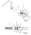
- FIG. 1 shows a threaded connection 1 between a tool 2 and an extension device 4.
- the tool 2 is a paint roller to which a threaded bush 6 is attached to the end face of the handle opposite the bracket.
- a threaded bolt 5 of the extension device 4 are screwed in until the extension device 4 is firmly connected to the tool 2 is.
- the tool side has a cam 8 and on the side of the extension device 4 has a cam associated with the recess 9.
- FIG. 1 shows two snap connections 7 arranged radially approximately opposite one another.
- the locking sleeve 10 during the screwing together of the extension device 4 with the handle of the tool 2 according to the direction of the arrow 10a spring loaded can be moved to the right.
- the opposite to the extension device rotatable but axially displaceable locking sleeve 10 is rotated so far with respect to the tool that the cam 8 associated recess in accordance with the cam 8, it snaps back under spring force against the direction of the previously executed sliding movement and takes the Cam 8 in order to produce the locking of the threaded connection 1. Further details can be taken from FIGS. 3 and 4.
- a locking device 12 is formed on the locking sleeve 10, by means of which they in turn can be pulled back axially in a direction of the arrow 10a to the right, so that the engagement of the cam 8 is released in the recess 9, according to which the extension device 4 can again be rotated in the opposite direction relative to the tool and thus screwed on.
- Figure 2 shows basically the same structure of a threaded connection 1 with threaded bolt 5 and threaded bushing 6 and a lock in the form of a positive Snap connection 7.
- a tool 2 is received by the extension device 4 and in Figure 2, a tool adapter 3.
- This tool adapter 3 extends the possibility of variation of the threaded connection.
- FIG. 3 shows further details of the threaded connection.
- This anti-rotation 13 is formed between a arranged in a locking ring 15 slot 14 and engaging in this slot rib 16.
- the locking ring 15 is rotatably connected to the extension device 4.
- the locking sleeve 10 can thus be moved only in the axial direction by moving the rib 16 in the slot 14 against the spring force of the spring 11, which in turn is axially supported against the radially inserted into the extension direction 4, spring-loaded clamping pin 17.
- the locking sleeve 10 additionally has two stops 18, 19, wherein the stop 18 is formed with respect to the clamping pin 17 as arranged on the locking sleeve end side, inwardly facing flange.
- the stop 19 is in turn formed on the opposite end face of the locking sleeve 10 relative to the securing ring 15 as a radially inwardly pointing flange. The locking sleeve can thus be moved axially between these two stop positions.
- the two snap connections 7 are designed so that each cam 8, due to different radial distances to the longitudinal axis of the threaded connection, can only engage in the recess 9 assigned to it.
- FIG. 4 shows this connection in a locked state, that is, in a joined state.
- the upper snap connection 7, as described in FIG. 3, differs from the lower snap connection 7.
- FIG. 5 shows this threaded connection in a non-cut representation in an oblique plan view.
- FIGS. 6a and 6b show, as partial cut-outs, further possibilities for an elastic snap connection, in which in turn a cam 8 engages in a recess 9 associated therewith.
- the locking takes place by rotating the cam on the surface of the counterpart associated with the recess.
- the cam having locking member must be elastically deformed relative to the recess 9 having locking element until the two engage by snapping into each other.
- both the cam 8 and the recess 9 each have an inclined surface 20.
- This inclined surface 20 refers to the cross section of the illustrated embodiment. Of course, these are two opposing, diagonally arranged surfaces, which reduces the restoring force when loosening the lock so far that it is easy to solve and yet properly secures this when using the tool.
- the snap connection is formed so that the cam 8 snaps radially inward into the recess and as shown in the figure 6b, this cam engages radially outward in the recess 9 assigned to it.
- FIG. 7 shows a further embodiment in which the cam 8 snaps radially inwards into the recess assigned to it.
- a handling device 12 is arranged here, which presses from the radially opposite side from the inside out the cam, so that the lock is released.
- the edge 20 associated side of the recess 9 is rounded here, so that the release of the lock is facilitated.
- FIGS 8, 8a and 8b show a further embodiment of a lock for a threaded connection.
- the threaded bolt 6 is arranged inside the handle for the tool 2, which may optionally be surrounded by a sleeve 22 in order to form a more user-friendly grip end.
- cams 8 are arranged on elastic tongues, so that they can be bent radially inwardly.
- the cams 8 are first inserted and compressed radially inwardly.
- the cams 8 snap radially outward into the associated recess 9.
- This recess 9 can now be either a circumferential groove or holes arranged at corresponding locations. These holes can be holes, recesses or something similar.
- a handling device 12 is provided, which is formed in this case in the form of a ring having inwardly directed pins. These pins press according to the illustration in Figure 8a upon compression of the ring, the two cams 8 in the direction of the arrows 21 radially together so that they again in the direction of the threaded bushing 5 can be unscrewed axially.
- FIG. 8b is a sectional view in the plane VIII-VIII in FIG. 8.
- the sliding connection can be realized by a modified form of the snap connection 7, in which the locking sleeve 10 without the restoring spring 11 is arranged on the threaded connection 1.
- the intermeshing of the cam 8 and the recess 9, for the purpose of locking the tool 2 on the extension device 4, is then effected in this embodiment not by moving the locking sleeve by means of a spring but by manually moving.
Landscapes
- Engineering & Computer Science (AREA)
- General Engineering & Computer Science (AREA)
- Mechanical Engineering (AREA)
- Mutual Connection Of Rods And Tubes (AREA)
- Gripping On Spindles (AREA)
- Coating Apparatus (AREA)
- Details Of Spanners, Wrenches, And Screw Drivers And Accessories (AREA)
Claims (10)
- Raccordement par filetage (1) comprenant :- une première partie de raccordement par filetage associée à un outil (2) ou un adaptateur d'outil (3), et- une deuxième partie de raccordement par filetage associée à un dispositif de prolongation (4),dans lequel la première partie de raccordement par filetage est un boulon fileté (5) ou une douille taraudée (6) et la deuxième partie de raccordement par filetage est une douille taraudée (6) complémentaire ou un boulon fileté (5) complémentaire à ceux-ci,
le boulon fileté (5) s'engage dans la douille taraudée (6) pour raccorder la première partie de raccordement par filetage à la deuxième partie de raccordement par filetage, et
le dispositif d'arrêt comporte entre la première partie de raccordement par filetage associée à l'outil (2) ou à l'adaptateur d'outil (3) et la deuxième partie de raccordement par filetage associée au dispositif de prolongation (4), un raccordement par encliquetage à liaison par la forme (7) sous forme de raccordement par encliquetage (7) ou de raccordement coulissant, auquel est associé un dispositif de manipulation (12) qui facilite le détachement du dispositif d'arrêt,
caractérisé en ce qu'
on associe au dispositif de manipulation (12) un moyen de rappel (11) à déformation élastique, à l'encontre de la force duquel l'action d'arrêt du raccordement par encliquetage à liaison par la forme (7) est neutralisable. - Raccordement par filetage selon la revendication 1,
caractérisé en ce que
le raccordement par encliquetage (7) comporte une came (8) qui s'encliquète dans un évidement (9) en ayant un effet d'arrêt lorsque le boulon fileté (5) est vissé dans la douille taraudée (6) à sa position solidement serrée. - Raccordement par filetage selon l'une des revendications précédentes,
caractérisé en ce que
la came (8) et/ou l'évidement (9) du raccordement par encliquetage (7) sont mobiles axialement, de préférence au moyen d'un manchon d'arrêt (10) mobile à l'encontre de la force d'un ressort (11). - Raccordement par filetage selon l'une des revendications précédentes,
caractérisé en ce que
la came (8) déplace axialement le manchon d'arrêt (10) pendant le vissage du raccordement par filetage (1). - Raccordement par filetage selon l'une des revendications précédentes,
caractérisé en ce que
le manchon d'arrêt (10) comporte un dispositif de sécurité anti-torsion (13) et/ou une butée (18, 19) dans la direction du déplacement, une butée (18) étant de préférence sous forme de goupille de serrage (17) commandée par ressort. - Raccordement par filetage selon l'une des revendications précédentes 1 à 3,
caractérisé en ce que
la came (8) et/ou l'évidement (9) du raccordement par encliquetage (7) comportent un bord incliné (20) qui, si l'action de la force par torsion de l'outil (2) ou de l'adaptateur d'outil (3) contre le dispositif de prolongation (4) est suffisante, neutralise l'action d'arrêt du raccordement par encliquetage (7). - Raccordement par filetage selon l'une des revendications 1, 2 ou 6,
caractérisé en ce que
la came (8) du raccordement par encliquetage (7) s'encliquète radialement vers l'intérieur dans l'évidement (9). - Raccordement par filetage selon l'une des revendications 1, 2 ou 6,
caractérisé en ce que
la came (8) du raccordement par encliquetage (7) s'encliquète radialement vers l'extérieur dans l'évidement (9). - Raccordement par filetage selon l'une des revendications 1, 2 ou 6 à 8,
caractérisé en ce que
l'évidement (9) est en forme de rainure. - Raccordement par filetage selon l'une des revendications 1, 2 ou 6 à 8,
caractérisé en ce que
l'évidement (9) est en forme de trou.
Priority Applications (1)
| Application Number | Priority Date | Filing Date | Title |
|---|---|---|---|
| PL05000432T PL1586228T3 (pl) | 2004-04-16 | 2005-01-12 | Połączenie gwintowe, w szczególności do mocowania narzędzia lub adaptera narzędziowego, na urządzeniu przedłużającym |
Applications Claiming Priority (2)
| Application Number | Priority Date | Filing Date | Title |
|---|---|---|---|
| DE102004019237 | 2004-04-16 | ||
| DE102004019237A DE102004019237A1 (de) | 2004-04-16 | 2004-04-16 | Gewindeverbindung, insbesondere zur Befestigung eines Werkzeugs oder eines Werkzeugadapters, an einer Verlängerungseinrichtung |
Publications (2)
| Publication Number | Publication Date |
|---|---|
| EP1586228A1 EP1586228A1 (fr) | 2005-10-19 |
| EP1586228B1 true EP1586228B1 (fr) | 2007-11-14 |
Family
ID=34933247
Family Applications (1)
| Application Number | Title | Priority Date | Filing Date |
|---|---|---|---|
| EP05000432A Expired - Lifetime EP1586228B1 (fr) | 2004-04-16 | 2005-01-12 | Raccordement de fil, en particulier à l'attachement d'un outil ou d'un adapteur d'outil, à un mécanisme de prolongation |
Country Status (8)
| Country | Link |
|---|---|
| US (1) | US7431342B2 (fr) |
| EP (1) | EP1586228B1 (fr) |
| AT (1) | ATE377930T1 (fr) |
| DE (2) | DE102004019237A1 (fr) |
| DK (1) | DK1586228T3 (fr) |
| ES (1) | ES2295984T3 (fr) |
| PL (1) | PL1586228T3 (fr) |
| PT (1) | PT1586228E (fr) |
Families Citing this family (12)
| Publication number | Priority date | Publication date | Assignee | Title |
|---|---|---|---|---|
| US20070299459A1 (en) * | 2006-06-26 | 2007-12-27 | X-Sten Corp. | Percutaneous Tissue Access Device |
| JP4589955B2 (ja) * | 2007-12-19 | 2010-12-01 | 積水化学工業株式会社 | 管状接続部材と継手部材との接続構造 |
| CN101752527B (zh) * | 2008-12-05 | 2012-10-17 | 鸿富锦精密工业(深圳)有限公司 | 固定机构及采用该固定机构的电子装置 |
| US8418643B2 (en) * | 2009-10-29 | 2013-04-16 | Nathan David Povich | Telescoping boat railing |
| DE202012003902U1 (de) * | 2012-04-19 | 2012-10-16 | Günter Urban | Rohrverbinder |
| US9708865B2 (en) * | 2012-12-13 | 2017-07-18 | Vetco Gray Inc. | Ratcheting anti-rotation lock for threaded connectors |
| US8800113B1 (en) * | 2013-03-15 | 2014-08-12 | Blackstone Medical, Inc. | Rigid modular connector |
| CN104841588A (zh) * | 2015-05-12 | 2015-08-19 | 朱德金 | 一种喷漆柜多联动套杆 |
| CN106089940B (zh) * | 2016-05-31 | 2018-07-06 | 国家电网公司 | 一种导叶中轴套螺栓锁锭装置 |
| US10617441B2 (en) | 2016-09-07 | 2020-04-14 | Vertos Medical, Inc. | Percutaneous lateral recess resection methods and instruments |
| EP3626906A1 (fr) * | 2018-09-18 | 2020-03-25 | Saage Treppenbau und Biegetechnik GmbH & Co. KG | Système de poteaux tubulaires, escalier, procédé de liaison de deux poteaux tubulaires |
| EP4539756A1 (fr) | 2022-06-16 | 2025-04-23 | Vertos Medical, Inc. | Ensemble d'instruments intégrés |
Family Cites Families (7)
| Publication number | Priority date | Publication date | Assignee | Title |
|---|---|---|---|---|
| US1531463A (en) * | 1924-10-28 | 1925-03-31 | John H Lawson | Rod joint or coupling |
| US1580694A (en) * | 1925-03-12 | 1926-04-13 | Harvey K Russell | Pipe coupling |
| GB789697A (en) * | 1955-08-30 | 1958-01-29 | Edwin Lloyd Ward | Improvements relating to joints for shafts, rods and the like |
| US5215336A (en) * | 1991-06-28 | 1993-06-01 | Shur-Lok Corporation | Coupling joint assembly with integral retention mechanism |
| US5188398A (en) * | 1992-01-02 | 1993-02-23 | General Electric Company | Redundantly locked fluid coupling |
| FR2726536A1 (fr) * | 1994-11-08 | 1996-05-10 | Barre Bernard | Dispositif d'obturation a verrouillage auto-activable |
| TW334672U (en) * | 1996-08-15 | 1998-06-21 | Chun-Li Xu | Improved assembled structure of a gardening tool |
-
2004
- 2004-04-16 DE DE102004019237A patent/DE102004019237A1/de not_active Withdrawn
-
2005
- 2005-01-12 PT PT05000432T patent/PT1586228E/pt unknown
- 2005-01-12 DE DE502005001921T patent/DE502005001921D1/de not_active Expired - Fee Related
- 2005-01-12 ES ES05000432T patent/ES2295984T3/es not_active Expired - Lifetime
- 2005-01-12 EP EP05000432A patent/EP1586228B1/fr not_active Expired - Lifetime
- 2005-01-12 DK DK05000432T patent/DK1586228T3/da active
- 2005-01-12 PL PL05000432T patent/PL1586228T3/pl unknown
- 2005-01-12 AT AT05000432T patent/ATE377930T1/de not_active IP Right Cessation
- 2005-03-17 US US11/082,490 patent/US7431342B2/en not_active Expired - Fee Related
Also Published As
| Publication number | Publication date |
|---|---|
| DE502005001921D1 (de) | 2007-12-27 |
| PT1586228E (pt) | 2008-02-21 |
| DK1586228T3 (da) | 2008-03-25 |
| PL1586228T3 (pl) | 2008-04-30 |
| US20050232691A1 (en) | 2005-10-20 |
| EP1586228A1 (fr) | 2005-10-19 |
| ES2295984T3 (es) | 2008-04-16 |
| DE102004019237A1 (de) | 2005-11-03 |
| US7431342B2 (en) | 2008-10-07 |
| ATE377930T1 (de) | 2007-11-15 |
Similar Documents
| Publication | Publication Date | Title |
|---|---|---|
| EP2318723B1 (fr) | Agencement de fixation avec compensation des tolerances | |
| EP1961976B1 (fr) | Dispositif de fixation | |
| EP2054977B1 (fr) | Connecteur pour montage sur paroi avant ou pour montage sur paroi arrière | |
| EP2961899B1 (fr) | Poignée de commande | |
| EP1515054A1 (fr) | Dispositif de compensation de tolérance | |
| EP1586228B1 (fr) | Raccordement de fil, en particulier à l'attachement d'un outil ou d'un adapteur d'outil, à un mécanisme de prolongation | |
| EP1454071A1 (fr) | Ecrou de raccordement concu pour visser des elements de construction sur un composant de type plaque | |
| WO1992012355A1 (fr) | Element d'accouplement pour l'assemblage par liaison de force d'un element exterieur avec un arbre | |
| EP3256089A1 (fr) | Mâchoire de serrage destinée à être montée sur une glissière d'une table d'opération | |
| WO2019101760A1 (fr) | Insert fileté en fil métallique | |
| DE102020128569B4 (de) | Neigungshebelbaugruppe | |
| DE102005032699A1 (de) | Befestigungsvorrichtung | |
| EP2495823A1 (fr) | Système de liaison d'un boîtier d'un connecteur à fiches avec un écrou | |
| EP0964493B1 (fr) | Entrée de câble de forme angulaire avec une lieu de séparation entre les deux branches | |
| DE602005004778T2 (de) | Geteilte spindel | |
| EP4012200B1 (fr) | Boulon d'encliquetage sollicité par ressort | |
| AT513192A2 (de) | Schließzylinder | |
| EP2102509A1 (fr) | Tirant et ensemble de modules assemblés par serrage à l'aide dudit tirant | |
| DE2142488A1 (de) | Lösbarer Schraubverbinddr, insbesondere zum Anschluß von Tafeln an Rahmen od. dgl | |
| DE202008016456U1 (de) | Gewindebolzen und Aufsteckadapter | |
| DE102023124389A1 (de) | Leiteranschlussklemme und Set aus einer Leiteranschlussklemme und einem Betätigungselement | |
| AT502399B1 (de) | Einrichtung zum festlegen eines tür- oder fenstergriffes | |
| DE102010055808A1 (de) | Befestigungsvorrichtung | |
| WO2010146018A1 (fr) | Système de fixation d'un panneau | |
| EP4299930B1 (fr) | Dispositif de liaison pour deux composants |
Legal Events
| Date | Code | Title | Description |
|---|---|---|---|
| PUAI | Public reference made under article 153(3) epc to a published international application that has entered the european phase |
Free format text: ORIGINAL CODE: 0009012 |
|
| AK | Designated contracting states |
Kind code of ref document: A1 Designated state(s): AT BE BG CH CY CZ DE DK EE ES FI FR GB GR HU IE IS IT LI LT LU MC NL PL PT RO SE SI SK TR |
|
| AX | Request for extension of the european patent |
Extension state: AL BA HR LV MK YU |
|
| 17P | Request for examination filed |
Effective date: 20060118 |
|
| AKX | Designation fees paid |
Designated state(s): AT BE BG CH CY CZ DE DK EE ES FI FR GB GR HU IE IS IT LI LT LU MC NL PL PT RO SE SI SK TR |
|
| 17Q | First examination report despatched |
Effective date: 20060220 |
|
| GRAP | Despatch of communication of intention to grant a patent |
Free format text: ORIGINAL CODE: EPIDOSNIGR1 |
|
| GRAS | Grant fee paid |
Free format text: ORIGINAL CODE: EPIDOSNIGR3 |
|
| GRAA | (expected) grant |
Free format text: ORIGINAL CODE: 0009210 |
|
| AK | Designated contracting states |
Kind code of ref document: B1 Designated state(s): AT BE BG CH CY CZ DE DK EE ES FI FR GB GR HU IE IS IT LI LT LU MC NL PL PT RO SE SI SK TR |
|
| REG | Reference to a national code |
Ref country code: GB Ref legal event code: FG4D Free format text: NOT ENGLISH |
|
| REG | Reference to a national code |
Ref country code: CH Ref legal event code: EP |
|
| REG | Reference to a national code |
Ref country code: IE Ref legal event code: FG4D Free format text: LANGUAGE OF EP DOCUMENT: GERMAN |
|
| REF | Corresponds to: |
Ref document number: 502005001921 Country of ref document: DE Date of ref document: 20071227 Kind code of ref document: P |
|
| REG | Reference to a national code |
Ref country code: CH Ref legal event code: NV Representative=s name: KELLER & PARTNER PATENTANWAELTE AG |
|
| REG | Reference to a national code |
Ref country code: RO Ref legal event code: EPE |
|
| REG | Reference to a national code |
Ref country code: SE Ref legal event code: TRGR |
|
| GBT | Gb: translation of ep patent filed (gb section 77(6)(a)/1977) |
Effective date: 20080117 |
|
| REG | Reference to a national code |
Ref country code: PT Ref legal event code: SC4A Free format text: AVAILABILITY OF NATIONAL TRANSLATION Effective date: 20080211 |
|
| REG | Reference to a national code |
Ref country code: GR Ref legal event code: EP Ref document number: 20080400286 Country of ref document: GR |
|
| REG | Reference to a national code |
Ref country code: DK Ref legal event code: T3 |
|
| REG | Reference to a national code |
Ref country code: ES Ref legal event code: FG2A Ref document number: 2295984 Country of ref document: ES Kind code of ref document: T3 |
|
| PGFP | Annual fee paid to national office [announced via postgrant information from national office to epo] |
Ref country code: DK Payment date: 20080114 Year of fee payment: 4 |
|
| REG | Reference to a national code |
Ref country code: PL Ref legal event code: T3 |
|
| PG25 | Lapsed in a contracting state [announced via postgrant information from national office to epo] |
Ref country code: LT Free format text: LAPSE BECAUSE OF FAILURE TO SUBMIT A TRANSLATION OF THE DESCRIPTION OR TO PAY THE FEE WITHIN THE PRESCRIBED TIME-LIMIT Effective date: 20071114 Ref country code: BG Free format text: LAPSE BECAUSE OF FAILURE TO SUBMIT A TRANSLATION OF THE DESCRIPTION OR TO PAY THE FEE WITHIN THE PRESCRIBED TIME-LIMIT Effective date: 20080214 Ref country code: IS Free format text: LAPSE BECAUSE OF FAILURE TO SUBMIT A TRANSLATION OF THE DESCRIPTION OR TO PAY THE FEE WITHIN THE PRESCRIBED TIME-LIMIT Effective date: 20080314 Ref country code: SI Free format text: LAPSE BECAUSE OF FAILURE TO SUBMIT A TRANSLATION OF THE DESCRIPTION OR TO PAY THE FEE WITHIN THE PRESCRIBED TIME-LIMIT Effective date: 20071114 |
|
| PGFP | Annual fee paid to national office [announced via postgrant information from national office to epo] |
Ref country code: FI Payment date: 20080115 Year of fee payment: 4 Ref country code: HU Payment date: 20080104 Year of fee payment: 4 Ref country code: IE Payment date: 20080122 Year of fee payment: 4 |
|
| PGFP | Annual fee paid to national office [announced via postgrant information from national office to epo] |
Ref country code: RO Payment date: 20080211 Year of fee payment: 4 Ref country code: AT Payment date: 20080114 Year of fee payment: 4 |
|
| REG | Reference to a national code |
Ref country code: HU Ref legal event code: AG4A Ref document number: E002921 Country of ref document: HU |
|
| ET | Fr: translation filed | ||
| PG25 | Lapsed in a contracting state [announced via postgrant information from national office to epo] |
Ref country code: MC Free format text: LAPSE BECAUSE OF NON-PAYMENT OF DUE FEES Effective date: 20080131 |
|
| PLBE | No opposition filed within time limit |
Free format text: ORIGINAL CODE: 0009261 |
|
| STAA | Information on the status of an ep patent application or granted ep patent |
Free format text: STATUS: NO OPPOSITION FILED WITHIN TIME LIMIT |
|
| PGFP | Annual fee paid to national office [announced via postgrant information from national office to epo] |
Ref country code: PT Payment date: 20080606 Year of fee payment: 4 |
|
| 26N | No opposition filed |
Effective date: 20080815 |
|
| PG25 | Lapsed in a contracting state [announced via postgrant information from national office to epo] |
Ref country code: EE Free format text: LAPSE BECAUSE OF FAILURE TO SUBMIT A TRANSLATION OF THE DESCRIPTION OR TO PAY THE FEE WITHIN THE PRESCRIBED TIME-LIMIT Effective date: 20071114 |
|
| PGFP | Annual fee paid to national office [announced via postgrant information from national office to epo] |
Ref country code: CH Payment date: 20081219 Year of fee payment: 5 |
|
| PGFP | Annual fee paid to national office [announced via postgrant information from national office to epo] |
Ref country code: ES Payment date: 20090122 Year of fee payment: 5 |
|
| PGFP | Annual fee paid to national office [announced via postgrant information from national office to epo] |
Ref country code: CZ Payment date: 20090106 Year of fee payment: 5 Ref country code: DE Payment date: 20090206 Year of fee payment: 5 Ref country code: NL Payment date: 20090114 Year of fee payment: 5 Ref country code: PL Payment date: 20090107 Year of fee payment: 5 Ref country code: SK Payment date: 20090108 Year of fee payment: 5 |
|
| PGFP | Annual fee paid to national office [announced via postgrant information from national office to epo] |
Ref country code: GB Payment date: 20090122 Year of fee payment: 5 |
|
| PG25 | Lapsed in a contracting state [announced via postgrant information from national office to epo] |
Ref country code: CY Free format text: LAPSE BECAUSE OF FAILURE TO SUBMIT A TRANSLATION OF THE DESCRIPTION OR TO PAY THE FEE WITHIN THE PRESCRIBED TIME-LIMIT Effective date: 20071114 |
|
| PGFP | Annual fee paid to national office [announced via postgrant information from national office to epo] |
Ref country code: BE Payment date: 20090219 Year of fee payment: 5 |
|
| PGFP | Annual fee paid to national office [announced via postgrant information from national office to epo] |
Ref country code: IT Payment date: 20090127 Year of fee payment: 5 Ref country code: SE Payment date: 20090114 Year of fee payment: 5 |
|
| REG | Reference to a national code |
Ref country code: DK Ref legal event code: EBP |
|
| PG25 | Lapsed in a contracting state [announced via postgrant information from national office to epo] |
Ref country code: FI Free format text: LAPSE BECAUSE OF NON-PAYMENT OF DUE FEES Effective date: 20090112 Ref country code: AT Free format text: LAPSE BECAUSE OF NON-PAYMENT OF DUE FEES Effective date: 20090112 |
|
| PGFP | Annual fee paid to national office [announced via postgrant information from national office to epo] |
Ref country code: FR Payment date: 20090115 Year of fee payment: 5 |
|
| PG25 | Lapsed in a contracting state [announced via postgrant information from national office to epo] |
Ref country code: HU Free format text: LAPSE BECAUSE OF NON-PAYMENT OF DUE FEES Effective date: 20090113 |
|
| PG25 | Lapsed in a contracting state [announced via postgrant information from national office to epo] |
Ref country code: IE Free format text: LAPSE BECAUSE OF NON-PAYMENT OF DUE FEES Effective date: 20090112 |
|
| PG25 | Lapsed in a contracting state [announced via postgrant information from national office to epo] |
Ref country code: GR Free format text: LAPSE BECAUSE OF NON-PAYMENT OF DUE FEES Effective date: 20090804 |
|
| PG25 | Lapsed in a contracting state [announced via postgrant information from national office to epo] |
Ref country code: RO Free format text: LAPSE BECAUSE OF NON-PAYMENT OF DUE FEES Effective date: 20090112 |
|
| REG | Reference to a national code |
Ref country code: PT Ref legal event code: MM4A Free format text: LAPSE DUE TO NON-PAYMENT OF FEES Effective date: 20100712 |
|
| PG25 | Lapsed in a contracting state [announced via postgrant information from national office to epo] |
Ref country code: LU Free format text: LAPSE BECAUSE OF NON-PAYMENT OF DUE FEES Effective date: 20080112 Ref country code: DK Free format text: LAPSE BECAUSE OF NON-PAYMENT OF DUE FEES Effective date: 20090731 |
|
| BERE | Be: lapsed |
Owner name: CIRET HOLDINGS A.G. Effective date: 20100131 |
|
| REG | Reference to a national code |
Ref country code: NL Ref legal event code: V1 Effective date: 20100801 |
|
| REG | Reference to a national code |
Ref country code: CH Ref legal event code: PL |
|
| GBPC | Gb: european patent ceased through non-payment of renewal fee |
Effective date: 20100112 |
|
| EUG | Se: european patent has lapsed | ||
| REG | Reference to a national code |
Ref country code: SK Ref legal event code: MM4A Ref document number: E 2982 Country of ref document: SK Effective date: 20100112 |
|
| REG | Reference to a national code |
Ref country code: FR Ref legal event code: ST Effective date: 20100930 |
|
| PG25 | Lapsed in a contracting state [announced via postgrant information from national office to epo] |
Ref country code: CH Free format text: LAPSE BECAUSE OF NON-PAYMENT OF DUE FEES Effective date: 20100131 Ref country code: FR Free format text: LAPSE BECAUSE OF NON-PAYMENT OF DUE FEES Effective date: 20100201 Ref country code: LI Free format text: LAPSE BECAUSE OF NON-PAYMENT OF DUE FEES Effective date: 20100131 Ref country code: NL Free format text: LAPSE BECAUSE OF NON-PAYMENT OF DUE FEES Effective date: 20100801 |
|
| PG25 | Lapsed in a contracting state [announced via postgrant information from national office to epo] |
Ref country code: DE Free format text: LAPSE BECAUSE OF NON-PAYMENT OF DUE FEES Effective date: 20100803 Ref country code: CZ Free format text: LAPSE BECAUSE OF NON-PAYMENT OF DUE FEES Effective date: 20100112 Ref country code: SK Free format text: LAPSE BECAUSE OF NON-PAYMENT OF DUE FEES Effective date: 20100112 |
|
| PG25 | Lapsed in a contracting state [announced via postgrant information from national office to epo] |
Ref country code: GB Free format text: LAPSE BECAUSE OF NON-PAYMENT OF DUE FEES Effective date: 20100112 |
|
| PG25 | Lapsed in a contracting state [announced via postgrant information from national office to epo] |
Ref country code: PT Free format text: LAPSE BECAUSE OF NON-PAYMENT OF DUE FEES Effective date: 20100712 |
|
| PG25 | Lapsed in a contracting state [announced via postgrant information from national office to epo] |
Ref country code: BE Free format text: LAPSE BECAUSE OF NON-PAYMENT OF DUE FEES Effective date: 20100131 |
|
| REG | Reference to a national code |
Ref country code: ES Ref legal event code: FD2A Effective date: 20110325 |
|
| PG25 | Lapsed in a contracting state [announced via postgrant information from national office to epo] |
Ref country code: IT Free format text: LAPSE BECAUSE OF NON-PAYMENT OF DUE FEES Effective date: 20100112 |
|
| PG25 | Lapsed in a contracting state [announced via postgrant information from national office to epo] |
Ref country code: ES Free format text: LAPSE BECAUSE OF NON-PAYMENT OF DUE FEES Effective date: 20110314 |
|
| PG25 | Lapsed in a contracting state [announced via postgrant information from national office to epo] |
Ref country code: ES Free format text: LAPSE BECAUSE OF NON-PAYMENT OF DUE FEES Effective date: 20100113 |
|
| PGFP | Annual fee paid to national office [announced via postgrant information from national office to epo] |
Ref country code: TR Payment date: 20081222 Year of fee payment: 5 |
|
| REG | Reference to a national code |
Ref country code: PL Ref legal event code: LAPE |
|
| PG25 | Lapsed in a contracting state [announced via postgrant information from national office to epo] |
Ref country code: PL Free format text: LAPSE BECAUSE OF NON-PAYMENT OF DUE FEES Effective date: 20100112 |
|
| PG25 | Lapsed in a contracting state [announced via postgrant information from national office to epo] |
Ref country code: SE Free format text: LAPSE BECAUSE OF NON-PAYMENT OF DUE FEES Effective date: 20100113 |
|
| PG25 | Lapsed in a contracting state [announced via postgrant information from national office to epo] |
Ref country code: TR Free format text: LAPSE BECAUSE OF NON-PAYMENT OF DUE FEES Effective date: 20100112 |