EP1586421B1 - Selbstkalibrierendes Orientierungssystem für ein Handhabungsgerät - Google Patents
Selbstkalibrierendes Orientierungssystem für ein Handhabungsgerät Download PDFInfo
- Publication number
- EP1586421B1 EP1586421B1 EP04012357A EP04012357A EP1586421B1 EP 1586421 B1 EP1586421 B1 EP 1586421B1 EP 04012357 A EP04012357 A EP 04012357A EP 04012357 A EP04012357 A EP 04012357A EP 1586421 B1 EP1586421 B1 EP 1586421B1
- Authority
- EP
- European Patent Office
- Prior art keywords
- sensor means
- action
- input space
- mapping function
- actuator
- Prior art date
- Legal status (The legal status is an assumption and is not a legal conclusion. Google has not performed a legal analysis and makes no representation as to the accuracy of the status listed.)
- Expired - Lifetime
Links
Images

Classifications
-
- B—PERFORMING OPERATIONS; TRANSPORTING
- B25—HAND TOOLS; PORTABLE POWER-DRIVEN TOOLS; MANIPULATORS
- B25J—MANIPULATORS; CHAMBERS PROVIDED WITH MANIPULATION DEVICES
- B25J9/00—Program-controlled manipulators
- B25J9/16—Program controls
- B25J9/1694—Program controls characterised by use of sensors other than normal servo-feedback from position, speed or acceleration sensors, perception control, multi-sensor controlled systems, sensor fusion
- B25J9/1697—Vision controlled systems
-
- G—PHYSICS
- G05—CONTROLLING; REGULATING
- G05B—CONTROL OR REGULATING SYSTEMS IN GENERAL; FUNCTIONAL ELEMENTS OF SUCH SYSTEMS; MONITORING OR TESTING ARRANGEMENTS FOR SUCH SYSTEMS OR ELEMENTS
- G05B19/00—Program-control systems
- G05B19/02—Program-control systems electric
- G05B19/18—Numerical control [NC], i.e. automatically operating machines, in particular machine tools, e.g. in a manufacturing environment, so as to execute positioning, movement or co-ordinated operations by means of program data in numerical form
- G05B19/401—Numerical control [NC], i.e. automatically operating machines, in particular machine tools, e.g. in a manufacturing environment, so as to execute positioning, movement or co-ordinated operations by means of program data in numerical form characterised by control arrangements for measuring, e.g. calibration and initialisation, measuring workpiece for machining purposes
-
- G—PHYSICS
- G05—CONTROLLING; REGULATING
- G05B—CONTROL OR REGULATING SYSTEMS IN GENERAL; FUNCTIONAL ELEMENTS OF SUCH SYSTEMS; MONITORING OR TESTING ARRANGEMENTS FOR SUCH SYSTEMS OR ELEMENTS
- G05B2219/00—Program-control systems
- G05B2219/30—Nc systems
- G05B2219/39—Robotics, robotics to robotics hand
- G05B2219/39367—Using a motion map, association between visual position and joint position
-
- G—PHYSICS
- G05—CONTROLLING; REGULATING
- G05B—CONTROL OR REGULATING SYSTEMS IN GENERAL; FUNCTIONAL ELEMENTS OF SUCH SYSTEMS; MONITORING OR TESTING ARRANGEMENTS FOR SUCH SYSTEMS OR ELEMENTS
- G05B2219/00—Program-control systems
- G05B2219/30—Nc systems
- G05B2219/39—Robotics, robotics to robotics hand
- G05B2219/39391—Visual servoing, track end effector with camera image feedback
-
- G—PHYSICS
- G05—CONTROLLING; REGULATING
- G05B—CONTROL OR REGULATING SYSTEMS IN GENERAL; FUNCTIONAL ELEMENTS OF SUCH SYSTEMS; MONITORING OR TESTING ARRANGEMENTS FOR SUCH SYSTEMS OR ELEMENTS
- G05B2219/00—Program-control systems
- G05B2219/30—Nc systems
- G05B2219/40—Robotics, robotics mapping to robotics vision
- G05B2219/40617—Agile eye, control position of camera, active vision, pan-tilt camera, follow object
Definitions
- the present invention relates to the control of an orienting/positioning device having sensor means, the input space of which can be changed by a defined planned real-world action carried out by a manipulator controlled by the orienting/positioning device.
- a manipulator controlled by the orienting/positioning device.
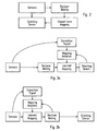
- Figure 1 thereby shows a stereo camera which can be the directed in several degrees-of-freedom. It is now assumed that the shown camera is to be directed such that a detected visual target present somewhere in the input space of the camera moves into the origin of the input space.
- Figure 2 shows a known process to calculate and carry out an action (i.e. movement of the camera) in order to achieve said object.
- the output of the sensor here: camera
- the output of the sensor is evaluated to make a decision regarding a target position in the multi-dimensional input space of the sensor, which target position can e.g. be a recognized visual target.
- the sensor coordinates are mapped into the motor coordinates (voltages, currents etc.) using a predefined look-up table or analytical function in order to generate the actuator (motor) command necessary for the before decided new orientation of the camera.
- Typical examples for sensor means providing explicit orientation information are e.g. an image sensor array, a radar image sensor array or a chemical receptor sensor array.
- a typical sensor means providing implicit orientation information is the use of stereo microphones to localise a sound source. Sensor means providing implicit orientation information require an extraction of the orientation information before said orientation information can be used.
- Robots comprising sensors which supply orientation information are known as orienting robots. It is a disadvantage of such orienting robots that they frequently require calibration to work properly. Such a calibration must be done after every change in system geometry (e.g. when the physical relation between a sensor and an actuator of the robot is changed), after every modification (e.g. lens replacement, a motor modification) and if the robot is used in a changing or uncontrolled environment.
- orienting robots It is a disadvantage of such orienting robots that they frequently require calibration to work properly. Such a calibration must be done after every change in system geometry (e.g. when the physical relation between a sensor and an actuator of the robot is changed), after every modification (e.g. lens replacement, a motor modification) and if the robot is used in a changing or uncontrolled environment.
- Such self-calibrating orienting robots usually use calibration scenarios, mathematical analysis or parameter/hardware tuning with human supervision.
- Calibration by mathematical analysis has the drawback that several implicit assumptions are necessary which frequently result in strong simplifications. Often only a subset of variations is taken into account. Thus, the accuracy of said calibration method usually is insufficient. Furthermore, calibration by mathematical analysis often is not applicable for online calibration due to the high complexity.
- Parameter/hardware tuning with human supervision has the drawback that it requires human expert intervention. Therefore, this calibration solution is not suitable for autonomous robots. Moreover, this calibration technique usually is very time consuming and highly depends on the experience of the expert.
- Robotic systems comprising sensor means, in particular cameras, to provide orientation information, being controlled by adaptive learning algorithms, are disclosed in the documents : BUESSLER J-L ET AL: "Visually guided movements: learning with modular neural maps in robotics” NEURAL NETWORKS, ELSEVIER SCIENCE PUBLISHERS, BARKING, GB, vol. 11, no. 7-8, 11 October 1998 (1998-10-11), pages 1395-1415, ISSN: 0893-6080 , as well as KUHN D ET AL: "Cooperation of neural networks applied to a robotic hand-eye coordination task" SYSTEMS, MAN AND CYBERNETICS, 1995.
- a method for controlling an orienting/positioning system comprising at least one sensor means and actuator means for controlling an orienting and/or positioning action of manipulating means such as e.g. a robot device which can be detected by the sensor means and which can interact with the real-world in order to change the input space of the sensor means as planned by the system.
- manipulating means such as e.g. a robot device which can be detected by the sensor means and which can interact with the real-world in order to change the input space of the sensor means as planned by the system.
- a correction signal can be calculated based on any difference of the real post-action position and the targeted position of the manipulating device in the input space of the sensor means.
- the mapping function can be adapted taking into account the correction signal and the pre-action position of the manipulating device in the input space of the sensor means.
- the adaptation vector Before adapting the mapping function, the adaptation vector can be multiplied with a factor larger than or equal to 0 and smaller than or equal to 1 in order to control the adaptation rate for the mapping function.
- the method can furthermore comprise the step of computing a confidence value based on the plausibility of the difference of the real post-action position and the targeted position of the manipulating device in the input space of the sensor means, e.g. by means of the correlation value of the selected patterns.
- the adaptation vector can then be modulated with the confidence value such that the adaptation rate depends on the confidence of e.g. the correlation between selected sensor patterns before and after the action.
- the mapping function can be implemented by means of a look-up table.
- the look-up table associates sensor coordinates with the corresponding actuator coordinates.
- steps S1 to S6 for each cycle, not only the position of the pattern, but also a neighbourhood in a defined range surrounding the pattern position is used, wherein the range of the neighbourhood can be changed between two subsequent cycles.
- the adaptation of the mapping function can be carried out in the sensor coordinates or in the actuator coordinates.
- Another aspect of the present invention relates to a method for controlling an orienting/positioning system, the orienting system comprising at least one sensor means and actuator means for controlling an orienting and/or positioning action of a manipulating device such as e.g. a robotic device which can be detected by the sensor means and which can interact with the real-world in order to change the input space of the sensor means as planned by the system.
- the method comprises preferably the following steps:
- Outputs of several sensor means can be individually mapped into actuator coordinates and then combined, wherein the decision in step S2 can be carried out on the basis of the result of the combination.
- Constraints of the actuator means can be taken into account when making the decision in step S2.
- Another aspect of the present invention relates to a computer software product adapted for implementing such a method when running on a computing device.
- a still other aspect of the present invention relates to an auto-calibrating orienting/positioning system.
- the system preferably comprises at least one sensor means, computing means and actuator means for controlling an orienting and/or positioning action of a manipulating device such as e.g. a robotic device which can be detected by the sensor means and which can interact with the real-world in order to change the input space of the sensor means as planned by the system, the computing means comprising:
- a process according to the present invention shall now be explained with reference to figure 3a .
- the output signal of a sensor is evaluated in order to make a decision regarding a target position of the manipulating device in the input space of the sensor means 1, which target position is to be achieved by a pre-calculated "one-strike” action.
- mapping the sensor coordinates of the decided action into actuator coordinates an adaptively learned mapping is used.
- a roughly estimated or arbitrarily set mapping function is used.
- an improved "learned" mapping function will be used.
- the success of the action i.e. whether the manipulating device has actually been brought close to the target position, is evaluated and depending on any deviation a correction signal is generated and fed to the mapping unit in order to carry out an incremental learning step.
- This cycle can be repeated until the deviation between the planned action and the real-world result is smaller than a preset threshold value. Alternatively the cycles can be repeated continuously.
- correction signal is generated after the action, which was meant to bring upon the desired result in one strike, has been completed.
- the action to be taken is decided in the sensor coordinates; the decision making result is then mapped to the actuator (motor) coordinates.
- Figure 3b shows an alternative arrangement in which the sensor coordinates are first mapped to the actuator coordinates before carrying out the decision making process in the actuator coordinate system.
- This arrangement has the advantage that e.g. restrictions on the actuator coordinates (maximum ranges, speed, acceleration etc.) can be easier taken into account during the decision now taking place in the actuator coordinates.
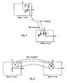
- figure 4 shows both a diagram of the sensor array and the motor array, respectively.
- the pre-action location S ⁇ x r - 1 is transferred to the centre of the sensor array (sensor input space).
- the corresponding actuator (motor) command be M ⁇ x t - 1 .
- the pre-action location S ⁇ x t - 1 is not exactly transferred to the target position in the sensor array, but to the post-action location S ⁇ x t .
- the incremental learning adaptation of the mapping function is carried out as an linear extrapolation, i.e.
- the learning process as shown in figure 4 can be applied both to the decision making strategies of figure 3a and figure 3b .
- this learning process can also be used in case of a single as well as multiple stimulus-emitting sources in the input space of the sensor(s).
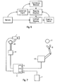
- Figure 6 shows schematically that a confidence measure can be derived from the correction signal, e.g. applying plausibility checks.
- the adaptation rate can then be modulated with the confidence measure (having a value between 0 and 1).
- the introduction of the confidence measure minimizes the occurrence of erroneous adaptation steps which can take place in case of incorrect estimations of the correction signal.
- the correction signal is usually computed by a correlation method, in which case the correlation can be used (after normalization) as a confidence measure.
- Fig. 7 schematically shows a self-calibrating orienting/positioning system according to the present invention.
- the system comprises sensor means 1 for gathering information of the real world in order to localise a manipulating device in the at least one-dimensional input space of the sensor means 1.
- the sensor means 1 may be a radar image sensor array, a chemical receptor sensor array or a stereo microphone for localising a sound emitted by the object 2 or any other directional sensor.
- the sensor means 1 is mounted on a frame comprising actuator means 41 and 42 which are e.g. adapted to tilt and pan the sensor means 1.
- said actuator means 41 and 42 can be e.g. electrical linear motors.
- the actuator means 41 and 42 are adapted to change the input space of the sensor means 1 by moving the sensor means 1 itself.
- any planned process adapted to change the input space of the sensor means 1 by a manipulation in the real world is called an “action” within the framework of the present specification.
- pre-action and post-action respectively, designates states before and after such an action controlled by the actuator means has taken place.
- Both the sensor means 1 and the actuator means 41 and 42 are connected to computing means 3.
- said computing means 3 is a computer which is adapted to define a targeted post-action position information of the manipulating device in the input space of the sensor means 1 and to calculate a command for the actuator means 41 and 42 to move the sensor means 1.
- the computing means can be adapted to calculate a command to move a manipulator 8 of a robot 43, the movement of the manipulator 8 also being an action suited to change the input space of the sensor means 1 under the control of the actuator means 41 and 42.
- the computing means uses pre-action position information provided by said sensor means 1, i.e. information on the position of the manipulating device in the input space of the sensor means 1 before the action has taken place, and a targeted post-action position information, i.e. an information representing a target position of the manipulating device 2 after the action has taken place.
- the target position can e.g. be the centre of the input space of the sensor means 1.
- the actuator means control e.g. the manipulator arm of a robot etc.
- the target position can be set as the position (still in the input space of the sensor means 1) of an object to be manipulated by the robot.
- the computing means 3 comprises a determining means 5 and a comparing means 6.
- the determining means 5 is adapted to determine whether a post-action position information output by the sensor means 1, after an action of said actuator means 41, 42 and/or said robot 43 with said object 2 and/or said manipulator 8 by moving said sensor means 1 or by moving said manipulator 8 is completed, coincides with the targeted post-action position as defined before by the computing means 3.
- the computing means 3 are further adapted to correct the calculated command for the actuator means 41, 42 and the manipulator 43, respectively by using the comparison result output by the comparing means 6.
- the corrected command can then be used for a future action.
- the corrected commands i.e. the adaptively learned mapping function, can be stored by the computing means 3 in said storing means 7 in said command-map.
- the commands stored in the command map are used by the computing means 3 to calculate any new commands for the actuator means 41, 42 and the manipulator 43, respectively.
- the inventive method allows an auto-calibration of the orienting system and an adaptation to changing and uncontrolled environments.
- the present invention provides a method of controlling an orienting system and a self-calibrating orienting system, which allows automatic calibration of the system without human intervention with high accuracy. Furthermore, the inventive method of controlling orienting system and the inventive self-calibrating orienting system is adapted to deal with non-linearities in motor/sensor responses and is suitable to be used in a changing and/or uncontrolled environment where maintenance is not possible or desired. Thus, a long-time operation of the inventive system and method without human interference is possible.
- the inventive system is simpler, more flexible and requires less maintenance than self-orienting / self-calibrating systems of the prior art.
- a change in the geometry of the inventive system is possible without necessitating a new calibration of the actuator means and the sensor means.
Landscapes
- Engineering & Computer Science (AREA)
- Robotics (AREA)
- Mechanical Engineering (AREA)
- Human Computer Interaction (AREA)
- Manufacturing & Machinery (AREA)
- Physics & Mathematics (AREA)
- General Physics & Mathematics (AREA)
- Automation & Control Theory (AREA)
- Manipulator (AREA)
- Feedback Control In General (AREA)
Claims (18)
- Verfahren zum Steuern eines Orientierungs-/Positionierungssystems, wobei das Orientierungssystem zumindest eine Sensoreinrichtung (1) und eine Stellgliedeinrichtung (41, 42, 43) aufweist, um eine Orientierungs- und/oder Positionierungsaktion einer Handhabungseinrichtung (8) und/oder der Sensoreinrichtung (1) zu steuern, wobei die Aktion das Ändern des Eingangsraums der Sensoreinrichtung (1) zur Folge hat,
wobei das Verfahren die folgenden Schritte aufweist:- (S1) Auswerten einer Voraktions-Ausgangsinformation der Sensoreinrichtung (1), um die Position der Handhabungseinrichtung im Eingangsraum der Sensoreinrichtung (1) zu erfassen;- (S2) Entscheiden über eine Ziel-Nachaktionsposition der Handhabungseinrichtung (2) im Eingangsraum der Sensoreinrichtung (1);- (S3) Definieren eines Befehls für die Stellgliedeinrichtung (41, 42, 43) durch Abbilden einer Abweichung der Voraktionsposition und der Ziel-Nachaktionsposition in den Eingangsraum-Koordinaten der Sensoreinrichtung (1), um Koordinaten unter Verwendung einer vorgegebenen Abbildungsfunktion stellglied-zusteuern;- (S4) Orientieren/Positionieren einer Handhabungseinrichtung durch die Stellgliedeinrichtung (41, 42, 43) gemäß dem definierten Befehl, um eine Orientierungs-/Positionierungs-Aktion auszuführen; und- (S5) Erfassen der realen Nachaktionsposition der Handhabungseinrichtung (2) im Eingangsraum der Sensoreinrichtung (1);- (S6) Adaptieren der Abbildungsfunktion, welche im Schritt S3 verwendet wird, auf Basis einer Differenz der realen Nachaktionsposition und der Ziel-Nachaktionsposition der Handhabungseinrichtung im Eingangsraum der Sensoreinrichtung (1), um ein inkrementales adaptives Lernen der Abbildungsfunktion auszuführen, wobei die Schritte S1 bis S6 zumindest einmal unter Verwendung der jeweiligen adaptierten Abbildungsfunktion zyklisch wiederholt werden, dadurch gekennzeichnet, dass
das Verfahren außerdem folgende Schritte aufweist:- Berechnen eines Vertrauenswerts auf Basis der Plausibilität der Differenz der realen Nachaktionsposition und der Ziel-Position der Handhabungseinrichtung; und- Modulieren des Adaptionsvektors mit dem Vertrauenswert so, dass die Adaptionsrate vom Vertrauenswert abhängt. - Verfahren nach Anspruch 1,
dadurch gekennzeichnet, dass
im Schritt S6- ein Korrektursignal auf Basis einer Differenz der realen Nachaktionsposition und der Ziel-Position der Handhabungseinrichtung im Eingangsraum der Sensoreinrichtung (1) berechnet wird, und- die Abbildungsfunktion angepasst wird, wobei das Korrektursignal, der ausgeführte Stellgliedbefehl und die Voraktionsposition der Handhabungseinrichtung im Eingangsraum der Sensoreinrichtung (1) in Betracht gezogen werden. - Verfahren zum Steuern eines Orientierungssystems nach Anspruch 2,
dadurch gekennzeichnet, dass
vor der Adaption der Abbildungsfunktion der Adaptionsvektor mit einem Faktor multipliziert ist, der größer oder gleich 0 und kleiner oder gleich als 1 ist, um die Adaptionsrate für Abbildungsfunktion zu steuern. - Verfahren nach einem der vorhergehenden Ansprüche,
dadurch gekennzeichnet, dass
die Abbildungsfunktion mittels einer Nachschlagetabelle verwirklicht wird. - Verfahren nach einem der vorhergehenden Ansprüche,
dadurch gekennzeichnet, dass
in den Schritten S1 bis S6 für jeden Zyklus nicht nur die Lage, sondern auch eine Nachbarschaft in einem definierten Bereich, der die Lage umgibt, verwendet wird. - Verfahren nach Anspruch 5,
dadurch gekennzeichnet, dass
der Bereich der Nachbarschaft zwischen zwei aufeinanderfolgenden Zyklen geändert werden kann. - Verfahren nach einem der vorhergehenden Ansprüche,
dadurch gekennzeichnet, dass
die Adaption der Abbildungsfunktion in den Sensorkoordinaten ausgeführt wird. - Verfahren nach einem der Ansprüche 1 bis 7,
dadurch gekennzeichnet, dass
die Adaption der Abbildungsfunktion in Stellgliedkoordinaten ausgeführt wird. - Verfahren nach einem der vorhergehenden Ansprüche, welches folgenden Schritt aufweist:- (S2) Entscheiden über die Ziel-Nachaktionsposition, wobei die Entscheidung in den Stellglied-Steuerkoordinaten stattfindet.
- Verfahren nach Anspruch 9,
dadurch gekennzeichnet, dass
Ausgangssignale mehrerer Sensoreinrichtungen individuell in Stellgliedkoordinaten abgebildet werden und dann kombiniert werden, wobei die Entscheidung im Schritt S2 in Bezug auf die Basis des Ergebnisses der Kombination ausgeführt wird. - Verfahren nach Anspruch 9 oder 10,
dadurch gekennzeichnet, dass
Beschränkungen des Stellglieds in Betracht gezogen werden, wenn die Entscheidung im Schritt S2 getroffen wird. - Computer-Software-Produkt, welches angepasst ist, ein Verfahren nach einem der vorhergehenden Ansprüche zu verwirklichen, wenn dies auf einer Computereinrichtung abläuft.
- Automatisches Kalibrierungs-Orientierungs-/Positionierungssystem, welches zumindest eine Sensoreinrichtung (1), eine Berechnungseinrichtung und eine Stellgliedeinrichtung (41, 42, 43) aufweist, um eine Orientierungs- und/oder Positionierungsaktion der Handhabungseinrichtung (8) und/oder der Sensoreinrichtung (1) zu steuern, wobei die Aktion das Ändern des Eingangsraums der Sensoreinrichtung (1) zur Folge hat,
wobei die Berechnungseinrichtung aufweist:- eine Einrichtung zum Auswerten von Voraktions-Ausgangsinformation der Sensoreinrichtung (1), um die Position der Handhabungseinrichtung im Eingangsraum der Sensoreinrichtung (1) zu erfassen;- eine Einrichtung zum Entscheiden über eine Ziel-Nachaktionsposition der Handhabungseinrichtung (2) im Eingangsraum der Sensoreinrichtung (1);- eine Einrichtung zum Befehligen der Stellgliedeinrichtung (41, 42, 43),wobei der Befehl durch Abbilden einer Abweichung des Voraktionsposition und der Ziel-Nachaktionsposition im Eingangsraum der Sensoreinrichtung (1) erzeugt wird, um Koordinaten unter Verwendung einer vorgegebenen Abbildungsfunktion stellgliedzu-steuern;- eine Einrichtung zum Erfassen der realen Nachaktionsposition der Handhabungseinrichtung im Eingangsraum der Sensoreinrichtung (1);- eine Einrichtung zum Kalibrieren der Abbildungsfunktion auf Basis einer Differenz der realen Nachaktionsposition und der Ziel-Nachaktionsposition der Handhabungseinrichtung im Eingangsraum der Sensoreinrichtung (1), um ein inkrementales adaptives Lernen der Abbildungsfunktion auszuführen, dadurch gekennzeichnet, dass diese außerdem aufweist:- eine Einrichtung zum Berechnen eines Vertrauenswerts auf Basis der Plausibilität der Differenz der realen Nachaktionsposition und Ziel-Nachaktionsposition der Handhabungseinrichtung, und- eine Einrichtung zum Modulieren des Adaptionsvektors mit dem Vertrauenswert, derart, dass die Adaptionsrate vom Vertrauenswert abhängt. - System nach Anspruch 13,
gekennzeichnet durch
eine Einrichtung zum Berechnen eines Korrektursignals auf Basis einer Differenz der realen Nachaktionsposition und der Ziel-Nachaktionsposition der Handhabungseinrichtung im Eingangsraum der Sensoreinrichtung (1),
wobei die Abbildungsfunktion kalibriert wird, wobei das Korrektursignal und die Voraktionsposition der Handhabungseinrichtung im Eingangsraum der Sensoreinrichtung (1) in Betracht gezogen werden. - System nach Anspruch 14,
dadurch gekennzeichnet, dass
vor der Kalibrierung der Abbildungsfunktion das Korrektursignal mit einem Faktor multipliziert wird, der größer als oder gleich 0 und kleiner als oder gleich 1 ist, um die Adaptionsrate für die Abbildungsfunktion zu steuern. - System nach einem der Ansprüche 14 oder 15,
dadurch gekennzeichnet, dass
die Abbildungsfunktion mittels einer Nachschlagetabelle verwirklicht wird. - System nach einem der Ansprüche 14 bis 16,
dadurch gekennzeichnet, dass
die Sensoreinrichtung zumindest eines von einer Kamera oder einem Mikrophon aufweist. - System nach einem der Ansprüche 14 bis 17,
dadurch gekennzeichnet, dass
die Handhabungseinrichtung eine Robotereinrichtung ist.
Priority Applications (3)
| Application Number | Priority Date | Filing Date | Title |
|---|---|---|---|
| EP04012357A EP1586421B1 (de) | 2004-04-16 | 2004-05-25 | Selbstkalibrierendes Orientierungssystem für ein Handhabungsgerät |
| JP2005039861A JP2005305633A (ja) | 2004-04-16 | 2005-02-16 | 操作デバイス用の自己較正指向システム |
| US11/101,952 US7509177B2 (en) | 2004-04-16 | 2005-04-08 | Self-calibrating orienting system for a manipulating device |
Applications Claiming Priority (3)
| Application Number | Priority Date | Filing Date | Title |
|---|---|---|---|
| EP04009122 | 2004-04-16 | ||
| EP04009122 | 2004-04-16 | ||
| EP04012357A EP1586421B1 (de) | 2004-04-16 | 2004-05-25 | Selbstkalibrierendes Orientierungssystem für ein Handhabungsgerät |
Publications (2)
| Publication Number | Publication Date |
|---|---|
| EP1586421A1 EP1586421A1 (de) | 2005-10-19 |
| EP1586421B1 true EP1586421B1 (de) | 2008-03-05 |
Family
ID=34925122
Family Applications (1)
| Application Number | Title | Priority Date | Filing Date |
|---|---|---|---|
| EP04012357A Expired - Lifetime EP1586421B1 (de) | 2004-04-16 | 2004-05-25 | Selbstkalibrierendes Orientierungssystem für ein Handhabungsgerät |
Country Status (3)
| Country | Link |
|---|---|
| US (1) | US7509177B2 (de) |
| EP (1) | EP1586421B1 (de) |
| JP (1) | JP2005305633A (de) |
Families Citing this family (13)
| Publication number | Priority date | Publication date | Assignee | Title |
|---|---|---|---|---|
| DE602004013720D1 (de) * | 2004-04-16 | 2008-06-26 | Honda Res Inst Europe Gmbh | Selbstkalibrierendes Sensororientierungssystem |
| EP1586421B1 (de) | 2004-04-16 | 2008-03-05 | Honda Research Institute Europe GmbH | Selbstkalibrierendes Orientierungssystem für ein Handhabungsgerät |
| EP1600791B1 (de) | 2004-05-26 | 2009-04-01 | Honda Research Institute Europe GmbH | Lokalisierung einer Schallquelle mittels binauraler Signale |
| DE602005005306T2 (de) * | 2005-05-31 | 2009-05-07 | Honda Research Institute Europe Gmbh | Steuerung der Bahn eines Greifers |
| DE602005008234D1 (de) * | 2005-08-10 | 2008-08-28 | Honda Res Inst Europe Gmbh | Erhöhung der Robustheit von online Kalibrierung durch Bewegungsdetektion |
| DE602006001051T2 (de) | 2006-01-09 | 2009-07-02 | Honda Research Institute Europe Gmbh | Bestimmung des entsprechenden Messfensters zur Schallquellenortung in Echoumgebungen |
| EP1862813A1 (de) | 2006-05-31 | 2007-12-05 | Honda Research Institute Europe GmbH | Verfahren zur Kalkulation der Position einer Schallquelle für Online-Kalibrierung von Hörsignalen zu Standorttransformationen |
| US20090192644A1 (en) * | 2008-01-30 | 2009-07-30 | Meyer Thomas J | Method and system for manufacturing an article using portable hand-held tools |
| US8412378B2 (en) * | 2009-12-02 | 2013-04-02 | GM Global Technology Operations LLC | In-vivo tension calibration in tendon-driven manipulators |
| JP6319736B2 (ja) * | 2013-09-19 | 2018-05-09 | 株式会社Ihi | センサの指向制御方法と装置 |
| US9211643B1 (en) | 2014-06-25 | 2015-12-15 | Microsoft Technology Licensing, Llc | Automatic in-situ registration and calibration of robotic arm/sensor/workspace system |
| EP3610993B1 (de) * | 2018-08-14 | 2025-04-09 | Beckman Coulter, Inc. | System zur aktiven bewegungsverschiebungssteuerung eines roboters |
| CN115072052B (zh) * | 2021-09-18 | 2024-01-05 | 苏州优斯登物联网科技有限公司 | 一种物料植入机构立料调节系统及物料自动包装设备 |
Family Cites Families (11)
| Publication number | Priority date | Publication date | Assignee | Title |
|---|---|---|---|---|
| GB2166889B (en) * | 1984-11-09 | 1988-01-06 | Ferranti Plc | Servo positioning system |
| US4852018A (en) * | 1987-01-07 | 1989-07-25 | Trustees Of Boston University | Massively parellel real-time network architectures for robots capable of self-calibrating their operating parameters through associative learning |
| US5083073A (en) * | 1990-09-20 | 1992-01-21 | Mazada Motor Manufacturing U.S.A. Corp. | Method and apparatus for calibrating a vision guided robot |
| US5294873A (en) | 1992-10-27 | 1994-03-15 | The United States Of America As Represented By The Administrator Of The National Aeronautics And Space Administration | Kinematic functions for redundancy resolution using configuration control |
| US20020099475A1 (en) | 2000-12-01 | 2002-07-25 | Ronald Spangler | Method and device for vibration control |
| US5960125A (en) * | 1996-11-21 | 1999-09-28 | Cognex Corporation | Nonfeedback-based machine vision method for determining a calibration relationship between a camera and a moveable object |
| US6687402B1 (en) * | 1998-12-18 | 2004-02-03 | Cognex Corporation | Machine vision methods and systems for boundary feature comparison of patterns and images |
| US20020099457A1 (en) * | 2001-01-25 | 2002-07-25 | Fredlund John R. | System and method for representing an activity involving a route along a plurality of locations |
| WO2003096054A2 (en) | 2002-05-10 | 2003-11-20 | Honda Giken Kogyo Kabushiki Kaisha | Real-time target tracking of an unpredictable target amid unknown obstacles |
| US7133570B1 (en) | 2003-02-06 | 2006-11-07 | Correlated Solutions, Inc. | Calibrated sensor and method for calibrating same |
| EP1586421B1 (de) | 2004-04-16 | 2008-03-05 | Honda Research Institute Europe GmbH | Selbstkalibrierendes Orientierungssystem für ein Handhabungsgerät |
-
2004
- 2004-05-25 EP EP04012357A patent/EP1586421B1/de not_active Expired - Lifetime
-
2005
- 2005-02-16 JP JP2005039861A patent/JP2005305633A/ja active Pending
- 2005-04-08 US US11/101,952 patent/US7509177B2/en not_active Expired - Fee Related
Also Published As
| Publication number | Publication date |
|---|---|
| JP2005305633A (ja) | 2005-11-04 |
| US7509177B2 (en) | 2009-03-24 |
| EP1586421A1 (de) | 2005-10-19 |
| US20050234566A1 (en) | 2005-10-20 |
Similar Documents
| Publication | Publication Date | Title |
|---|---|---|
| EP1587162B1 (de) | Selbstkalibrierendes Sensororientierungssystem | |
| US10618164B2 (en) | Robot system having learning control function and learning control method | |
| US9381643B2 (en) | Dynamical system-based robot velocity control | |
| EP2781314A1 (de) | Roboterkommissioniersystem, Steuerungsvorrichtung und Verfahren zur Herstellung eines Werkstücks | |
| US7509177B2 (en) | Self-calibrating orienting system for a manipulating device | |
| CN104858876A (zh) | 机器人任务的可视调试 | |
| WO2000045229A1 (en) | Uncalibrated dynamic mechanical system controller | |
| CN108356823A (zh) | 具有学习控制功能的控制系统以及控制方法 | |
| EP4175795B1 (de) | Transfer zwischen tasks in verschiedenen domänen | |
| EP2818283A1 (de) | Verfahren zum Kalibrieren eines Roboters | |
| JPH07266272A (ja) | マニピュレータ用追従方法及び装置 | |
| US20240026645A1 (en) | Construction machines with reduced latency actuator controls | |
| JP2020025992A (ja) | 制御装置、制御方法、およびプログラム | |
| US20220258335A1 (en) | Method and manipulation system for manipulation of an object by a robot | |
| CN109421049A (zh) | 机器人系统 | |
| EP2026589B1 (de) | Online-Kalibrierung von Stereokamerasystemen mit Feinvergenzbewegungen | |
| EP1752263B1 (de) | Erhöhung der Robustheit von online Kalibrierung durch Bewegungsdetektion | |
| US20240201677A1 (en) | Human skill learning by inverse reinforcement learning | |
| JPWO2020255312A1 (ja) | ロボットの動作調整装置、動作制御システムおよびロボットシステム | |
| CN100549891C (zh) | 用于控制定向/定位系统的方法和自动校准定向/定位系统 | |
| Sacchi et al. | A configuration space reference generation approach for real-time collision avoidance of industrial robot manipulators | |
| Liang et al. | Adaptive Hybrid Vision and Force Control for Dual-Arm Robotic Assembly Tasks | |
| Cheng et al. | Autonomous robot teaching using a smart robot in production line | |
| KR20000066931A (ko) | 인터넷을 이용한 원격 이동 로봇의 인터넷 직접 제어 시스템 및그 방법 | |
| Matsuno et al. | Uncalibrated Vision-Based Neural Network Control of Robots |
Legal Events
| Date | Code | Title | Description |
|---|---|---|---|
| PUAI | Public reference made under article 153(3) epc to a published international application that has entered the european phase |
Free format text: ORIGINAL CODE: 0009012 |
|
| AK | Designated contracting states |
Kind code of ref document: A1 Designated state(s): AT BE BG CH CY CZ DE DK EE ES FI FR GB GR HU IE IT LI LU MC NL PL PT RO SE SI SK TR |
|
| AX | Request for extension of the european patent |
Extension state: AL HR LT LV MK |
|
| 17P | Request for examination filed |
Effective date: 20060220 |
|
| AKX | Designation fees paid |
Designated state(s): DE FR GB |
|
| 17Q | First examination report despatched |
Effective date: 20060523 |
|
| GRAP | Despatch of communication of intention to grant a patent |
Free format text: ORIGINAL CODE: EPIDOSNIGR1 |
|
| GRAS | Grant fee paid |
Free format text: ORIGINAL CODE: EPIDOSNIGR3 |
|
| GRAA | (expected) grant |
Free format text: ORIGINAL CODE: 0009210 |
|
| AK | Designated contracting states |
Kind code of ref document: B1 Designated state(s): DE FR GB |
|
| REG | Reference to a national code |
Ref country code: GB Ref legal event code: FG4D |
|
| REF | Corresponds to: |
Ref document number: 602004012228 Country of ref document: DE Date of ref document: 20080417 Kind code of ref document: P |
|
| ET | Fr: translation filed | ||
| PLBE | No opposition filed within time limit |
Free format text: ORIGINAL CODE: 0009261 |
|
| STAA | Information on the status of an ep patent application or granted ep patent |
Free format text: STATUS: NO OPPOSITION FILED WITHIN TIME LIMIT |
|
| 26N | No opposition filed |
Effective date: 20081208 |
|
| PGFP | Annual fee paid to national office [announced via postgrant information from national office to epo] |
Ref country code: GB Payment date: 20140520 Year of fee payment: 11 |
|
| PGFP | Annual fee paid to national office [announced via postgrant information from national office to epo] |
Ref country code: FR Payment date: 20140516 Year of fee payment: 11 |
|
| REG | Reference to a national code |
Ref country code: DE Ref legal event code: R084 Ref document number: 602004012228 Country of ref document: DE Effective date: 20140711 |
|
| PGFP | Annual fee paid to national office [announced via postgrant information from national office to epo] |
Ref country code: DE Payment date: 20140730 Year of fee payment: 11 |
|
| REG | Reference to a national code |
Ref country code: GB Ref legal event code: 746 Effective date: 20150323 |
|
| REG | Reference to a national code |
Ref country code: DE Ref legal event code: R119 Ref document number: 602004012228 Country of ref document: DE |
|
| GBPC | Gb: european patent ceased through non-payment of renewal fee |
Effective date: 20150525 |
|
| REG | Reference to a national code |
Ref country code: FR Ref legal event code: ST Effective date: 20160129 |
|
| PG25 | Lapsed in a contracting state [announced via postgrant information from national office to epo] |
Ref country code: DE Free format text: LAPSE BECAUSE OF NON-PAYMENT OF DUE FEES Effective date: 20151201 Ref country code: GB Free format text: LAPSE BECAUSE OF NON-PAYMENT OF DUE FEES Effective date: 20150525 |
|
| PG25 | Lapsed in a contracting state [announced via postgrant information from national office to epo] |
Ref country code: FR Free format text: LAPSE BECAUSE OF NON-PAYMENT OF DUE FEES Effective date: 20150601 |