EP1586443A2 - Hitze-und Schallschutzvorrichtung - Google Patents
Hitze-und Schallschutzvorrichtung Download PDFInfo
- Publication number
- EP1586443A2 EP1586443A2 EP05290857A EP05290857A EP1586443A2 EP 1586443 A2 EP1586443 A2 EP 1586443A2 EP 05290857 A EP05290857 A EP 05290857A EP 05290857 A EP05290857 A EP 05290857A EP 1586443 A2 EP1586443 A2 EP 1586443A2
- Authority
- EP
- European Patent Office
- Prior art keywords
- wall
- intermediate layer
- thermal
- fixing means
- noise
- Prior art date
- Legal status (The legal status is an assumption and is not a legal conclusion. Google has not performed a legal analysis and makes no representation as to the accuracy of the status listed.)
- Withdrawn
Links
- 230000001681 protective effect Effects 0.000 title abstract 2
- 238000010521 absorption reaction Methods 0.000 claims abstract description 8
- 238000009413 insulation Methods 0.000 claims abstract description 6
- 230000004224 protection Effects 0.000 claims description 15
- VYPSYNLAJGMNEJ-UHFFFAOYSA-N Silicium dioxide Chemical compound O=[Si]=O VYPSYNLAJGMNEJ-UHFFFAOYSA-N 0.000 claims description 14
- 239000004744 fabric Substances 0.000 claims description 7
- 239000011521 glass Substances 0.000 claims description 7
- 239000000377 silicon dioxide Substances 0.000 claims description 7
- 239000011248 coating agent Substances 0.000 claims description 4
- 238000000576 coating method Methods 0.000 claims description 4
- 125000006850 spacer group Chemical group 0.000 claims description 3
- 239000000835 fiber Substances 0.000 claims description 2
- 239000003365 glass fiber Substances 0.000 claims description 2
- 238000010438 heat treatment Methods 0.000 claims description 2
- 229910052751 metal Inorganic materials 0.000 claims description 2
- 239000002184 metal Substances 0.000 claims description 2
- 239000002557 mineral fiber Substances 0.000 claims description 2
- 239000011490 mineral wool Substances 0.000 claims description 2
- 239000000203 mixture Substances 0.000 claims description 2
- 229910001220 stainless steel Inorganic materials 0.000 claims description 2
- 239000010935 stainless steel Substances 0.000 claims description 2
- 238000004826 seaming Methods 0.000 abstract 1
- 238000009958 sewing Methods 0.000 description 4
- 239000011888 foil Substances 0.000 description 3
- 239000007769 metal material Substances 0.000 description 3
- 229910052782 aluminium Inorganic materials 0.000 description 2
- XAGFODPZIPBFFR-UHFFFAOYSA-N aluminium Chemical compound [Al] XAGFODPZIPBFFR-UHFFFAOYSA-N 0.000 description 2
- 238000004519 manufacturing process Methods 0.000 description 2
- 239000004809 Teflon Substances 0.000 description 1
- 229920006362 Teflon® Polymers 0.000 description 1
- 230000002745 absorbent Effects 0.000 description 1
- 239000002250 absorbent Substances 0.000 description 1
- 230000003197 catalytic effect Effects 0.000 description 1
- 230000000295 complement effect Effects 0.000 description 1
- 239000000428 dust Substances 0.000 description 1
- 239000012530 fluid Substances 0.000 description 1
- 239000003292 glue Substances 0.000 description 1
- 239000005300 metallic glass Substances 0.000 description 1
- 238000010792 warming Methods 0.000 description 1
Images
Classifications
-
- B—PERFORMING OPERATIONS; TRANSPORTING
- B32—LAYERED PRODUCTS
- B32B—LAYERED PRODUCTS, i.e. PRODUCTS BUILT-UP OF STRATA OF FLAT OR NON-FLAT, e.g. CELLULAR OR HONEYCOMB, FORM
- B32B5/00—Layered products characterised by the non- homogeneity or physical structure, i.e. comprising a fibrous, filamentary, particulate or foam layer; Layered products characterised by having a layer differing constitutionally or physically in different parts
- B32B5/02—Layered products characterised by the non- homogeneity or physical structure, i.e. comprising a fibrous, filamentary, particulate or foam layer; Layered products characterised by having a layer differing constitutionally or physically in different parts characterised by structural features of a fibrous or filamentary layer
- B32B5/08—Layered products characterised by the non- homogeneity or physical structure, i.e. comprising a fibrous, filamentary, particulate or foam layer; Layered products characterised by having a layer differing constitutionally or physically in different parts characterised by structural features of a fibrous or filamentary layer the fibres or filaments of a layer being of different substances, e.g. conjugate fibres, mixture of different fibres
-
- B—PERFORMING OPERATIONS; TRANSPORTING
- B32—LAYERED PRODUCTS
- B32B—LAYERED PRODUCTS, i.e. PRODUCTS BUILT-UP OF STRATA OF FLAT OR NON-FLAT, e.g. CELLULAR OR HONEYCOMB, FORM
- B32B7/00—Layered products characterised by the relation between layers; Layered products characterised by the relative orientation of features between layers, or by the relative values of a measurable parameter between layers, i.e. products comprising layers having different physical, chemical or physicochemical properties; Layered products characterised by the interconnection of layers
- B32B7/04—Interconnection of layers
- B32B7/08—Interconnection of layers by mechanical means
-
- B—PERFORMING OPERATIONS; TRANSPORTING
- B32—LAYERED PRODUCTS
- B32B—LAYERED PRODUCTS, i.e. PRODUCTS BUILT-UP OF STRATA OF FLAT OR NON-FLAT, e.g. CELLULAR OR HONEYCOMB, FORM
- B32B15/00—Layered products comprising a layer of metal
- B32B15/14—Layered products comprising a layer of metal next to a fibrous or filamentary layer
-
- B—PERFORMING OPERATIONS; TRANSPORTING
- B32—LAYERED PRODUCTS
- B32B—LAYERED PRODUCTS, i.e. PRODUCTS BUILT-UP OF STRATA OF FLAT OR NON-FLAT, e.g. CELLULAR OR HONEYCOMB, FORM
- B32B5/00—Layered products characterised by the non- homogeneity or physical structure, i.e. comprising a fibrous, filamentary, particulate or foam layer; Layered products characterised by having a layer differing constitutionally or physically in different parts
- B32B5/22—Layered products characterised by the non- homogeneity or physical structure, i.e. comprising a fibrous, filamentary, particulate or foam layer; Layered products characterised by having a layer differing constitutionally or physically in different parts characterised by the presence of two or more layers which are next to each other and are fibrous, filamentary, formed of particles or foamed
- B32B5/24—Layered products characterised by the non- homogeneity or physical structure, i.e. comprising a fibrous, filamentary, particulate or foam layer; Layered products characterised by having a layer differing constitutionally or physically in different parts characterised by the presence of two or more layers which are next to each other and are fibrous, filamentary, formed of particles or foamed one layer being a fibrous or filamentary layer
- B32B5/26—Layered products characterised by the non- homogeneity or physical structure, i.e. comprising a fibrous, filamentary, particulate or foam layer; Layered products characterised by having a layer differing constitutionally or physically in different parts characterised by the presence of two or more layers which are next to each other and are fibrous, filamentary, formed of particles or foamed one layer being a fibrous or filamentary layer another layer next to it also being fibrous or filamentary
-
- B—PERFORMING OPERATIONS; TRANSPORTING
- B32—LAYERED PRODUCTS
- B32B—LAYERED PRODUCTS, i.e. PRODUCTS BUILT-UP OF STRATA OF FLAT OR NON-FLAT, e.g. CELLULAR OR HONEYCOMB, FORM
- B32B7/00—Layered products characterised by the relation between layers; Layered products characterised by the relative orientation of features between layers, or by the relative values of a measurable parameter between layers, i.e. products comprising layers having different physical, chemical or physicochemical properties; Layered products characterised by the interconnection of layers
- B32B7/02—Physical, chemical or physicochemical properties
-
- B—PERFORMING OPERATIONS; TRANSPORTING
- B32—LAYERED PRODUCTS
- B32B—LAYERED PRODUCTS, i.e. PRODUCTS BUILT-UP OF STRATA OF FLAT OR NON-FLAT, e.g. CELLULAR OR HONEYCOMB, FORM
- B32B2262/00—Composition or structural features of fibres which form a fibrous or filamentary layer or are present as additives
- B32B2262/10—Inorganic fibres
- B32B2262/101—Glass fibres
-
- B—PERFORMING OPERATIONS; TRANSPORTING
- B32—LAYERED PRODUCTS
- B32B—LAYERED PRODUCTS, i.e. PRODUCTS BUILT-UP OF STRATA OF FLAT OR NON-FLAT, e.g. CELLULAR OR HONEYCOMB, FORM
- B32B2307/00—Properties of the layers or laminate
- B32B2307/10—Properties of the layers or laminate having particular acoustical properties
- B32B2307/102—Insulating
-
- B—PERFORMING OPERATIONS; TRANSPORTING
- B32—LAYERED PRODUCTS
- B32B—LAYERED PRODUCTS, i.e. PRODUCTS BUILT-UP OF STRATA OF FLAT OR NON-FLAT, e.g. CELLULAR OR HONEYCOMB, FORM
- B32B2307/00—Properties of the layers or laminate
- B32B2307/30—Properties of the layers or laminate having particular thermal properties
- B32B2307/304—Insulating
-
- B—PERFORMING OPERATIONS; TRANSPORTING
- B32—LAYERED PRODUCTS
- B32B—LAYERED PRODUCTS, i.e. PRODUCTS BUILT-UP OF STRATA OF FLAT OR NON-FLAT, e.g. CELLULAR OR HONEYCOMB, FORM
- B32B2605/00—Vehicles
- B32B2605/08—Cars
Definitions
- the invention relates to a thermal and acoustic protection device with respect to of an element likely to emit heat and noise as well as thermally protected assembly comprising such a device and an element likely to emit heat and noise.
- the element is formed by at least a part an exhaust system of a motor vehicle.
- the exhaust line typically extending from the collector to the pot of relaxation, is a source of heat.
- the exhaust line can emit noises. Otherwise, it is subject to significant vibrations due to the operation of the engine.
- the wall may be provided with openings, for example in the form of perforations, able to allow the propagation of sound waves within the layer porous and their attenuation by absorption.
- these screens are fixed on a support, for example the line exhaust or a component to be protected from heat, usually by through fastening means passing through the screens through orifices provided to this end.
- a support for example the line exhaust or a component to be protected from heat
- fastening means passing through the screens through orifices provided to this end.
- Such orifices have the disadvantage of forming leaks thermal and acoustic.
- the vibrations generated by the exhaust line can reduce the efficiency fastening means which are subject to wear or even recess of the support.
- the aim of the invention is to overcome these drawbacks by proposing a device for flexible thermal and acoustic protection to confine heat and noise around their source, not requiring formatting or steps combination of complex layers and reliably set against the element likely to emit heat and noise.
- the invention relates to a device for thermal and acoustic protection with respect to an element likely to emit of heat and noise, said device comprising at least one inner wall and a flexible outer wall, said inner wall being adapted to be arranged facing the element, said device further comprising a layer Flexible and porous intermediate with absorption properties acoustic and thermal insulation, said intermediate layer being arranged between the inner wall and the outer wall, said device comprising means for fixing, the inner wall comprising openings allowing the passage sound waves to the middle layer, the inner and outer walls as well as the intermediate layer are associated with each other by sewing by means of a thread.
- the device substantially surrounds the element, which makes it possible to confine the heat and the noise emitted by it.
- the presence of openings in the internal wall allows efficient absorption of noise emitted by the element.
- no stamping step is necessary to its manufacture.
- the combination of layers by sewing is particularly simple and can achieve the openings in the inner wall.
- the invention relates to a protected assembly thermally comprising an element capable of emitting heat and noise and a device as described above, said device being arranged substantially around the element.
- the element is formed by at least a part of a motor vehicle exhaust system.
- FIG. 1 is a schematic representation in section of a device for protection according to the invention, said device being arranged around an element likely to emit heat and noise.
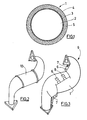
- FIG. 2 is a schematic representation in perspective of a part an exhaust system of a motor vehicle.
- FIG. 3 is a schematic representation in perspective of a set thermally protected comprising the exhaust line portion of the Figure 2 around which a device according to the invention is arranged.
- a device 1 for thermal and acoustic protection with respect to an element 2 capable of emitting heat and noise includes at least one inner wall 3 and one outer wall 4 and one layer intermediate 5 disposed between the inner wall 3 and the outer wall 4.
- the inner wall 3 is flexible. It is for example made of a glass fabric or silica.
- the glass fabric is particularly suitable for temperatures up to 550 ° C while silica is more suitable for temperatures up to 1100 ° C.
- the inner wall may also be able to reflect the heat.
- it may be made of a metallic material or glass or silica fabric further comprising a metallic material.
- the inner wall 3 is intended to be arranged facing the element 2, by example in contact with the outer wall thereof.
- the inner wall 3 includes openings (not shown) so as to allow the propagation of the sound waves within the intermediate layer 5 and their absorption attenuation.
- the openings can be made by perforations in the inner wall 3.
- the inner wall 3 is porous so as to comprise openings.
- the intermediate layer 5 is flexible and porous so as to present sound absorption and thermal insulation properties.
- Layer intermediate 5 is for example made of a felt of mineral fibers, such glass fibers (temperatures up to 550 ° C), basalt or rockwool (temperatures up to 750 ° C).
- the outer wall 4 is flexible.
- the outer wall 4 is for example made in one glass fabric comprising a coating.
- the coating can be Teflon for temperatures up to 250 ° C.
- the glass fabric can be associated with a metal foil such as aluminum foil for temperatures up to 600 ° C.
- the outer wall 4 may be able to reflect heat in from element 2 and to limit its exit to the external environment of the element 2.
- the outer wall 4 is provided with a metallic material.
- the coating or the aluminum foil make the outer wall 4 tight and provide protection of the device 1 with respect to fluids, dust and chippings. In addition, this seal improves the thermal insulation properties of the device 1.
- the inner and outer walls 3 and 4 intermediate 5 are associated with each other by a sewing performed at means of a wire comprising for example a mixture of silica and stainless steel fibers having suitable heat resistance characteristics.
- the inner wall 3 and the layer intermediate 5 are co-needled.
- This co-needling makes it possible to perform perforations in the inner wall 3 with a perforation rate adapted to the passage of sound waves and thermal protection with respect to element 2.
- the device 1 comprises a spacer (not shown), arranged to separate the inner wall 3 of the element 2.
- the inner wall can reflect the heat emitted by the element 2.
- a spacer comprises by example a grid arranged between the inner wall 3 and the element 2.
- the grid is designed to withstand the temperatures of element 2 and can for example be made of glass or silica.
- the device when it is not arranged around an element 2, presents itself flat and is likely to be folded back on itself because of its flexibility. So, no stamping step to shape it is necessary.
- the device 1 comprises fixing means 6.
- these fastening means 6 make it possible to close the device 1 on itself so as to form a sleeve around the element 2, as shown in FIG. 3.
- strips are provided hook-and-loop fasteners arranged in end portions of the device 1 intended to be facing each other when the device is arranged around a element 2.
- the fastening means 6 can be distributed along the device 1 so as to ensure a closure effective of the device 1 on itself.
- the device 1 forms a sleeve around the element 2, thus ensuring optimized acoustic and thermal protection.
- the device 1 does not completely surround element 2.
- the means 6 are intended to cooperate with reciprocal fixing means (not shown) provided in the external environment of the device 1. These reciprocal fixing means may in particular be provided on the element 2.
- the fastening means 6 then comprise, for example, hooks provided to engage in the means of reciprocal fixation of the environment of the device 1 or buttons provided to engage in supports corresponding to the environment of the device 1. It should be noted that these means 6 do not pass through the device 1, which prevents acoustic leakage and thermal at these fastening means.
- the device 1 has a geometry arranged to grip the element 2, when it is arranged around it. So for an element 2 substantially cylindrical, the device 1 has a substantially cylindrical shape when is arranged around the element 2.
- the device 1 has a geometry substantially complementary to that of element 2 when it is arranged on element 2, as can be seen by comparing Figures 2 and 3.
- a thermally protected assembly 9 is thus formed.
- a set 9 includes an element 2 capable of emitting heat and noise and a device 1 as described above.
- the device 1 is arranged around the element 2 and closed on itself around of it so as to form a sleeve.
- the assembly 9 may comprise a plurality of devices of thermal and acoustic protection 1, placed next to one another to substantially surround the entire element 2. This is particularly useful when element 2 has a significant length or shape particularly complex.
- the devices 1 are then associated with each other others by sewing.
- the element 2 is formed by a part 10 of exhaust line of a motor vehicle as shown in the figure 2.
- a part 10 is for example a precatalytic pot.
- the device 1 can include heating means to allow warming vehicle exhaust, in order to improve the performance of the vehicle pre-catalytic pot operation from the beginning of use of the vehicle.
- heating means are for example formed by electrical resistors.
- element 2 can be formed by any member of a motor vehicle capable of generating heat and noise.
- the device can be arranged on any element likely to generate heat and noise that we want to confine.
Landscapes
- Engineering & Computer Science (AREA)
- Mechanical Engineering (AREA)
- Exhaust Silencers (AREA)
- Building Environments (AREA)
Applications Claiming Priority (2)
| Application Number | Priority Date | Filing Date | Title |
|---|---|---|---|
| FR0404065 | 2004-04-16 | ||
| FR0404065A FR2868985B1 (fr) | 2004-04-16 | 2004-04-16 | Dispositif de protection thermique et acoustique vis a vis d'un element, ledit dispositif formant manchon autour dudit element |
Publications (1)
| Publication Number | Publication Date |
|---|---|
| EP1586443A2 true EP1586443A2 (de) | 2005-10-19 |
Family
ID=34942157
Family Applications (1)
| Application Number | Title | Priority Date | Filing Date |
|---|---|---|---|
| EP05290857A Withdrawn EP1586443A2 (de) | 2004-04-16 | 2005-04-18 | Hitze-und Schallschutzvorrichtung |
Country Status (2)
| Country | Link |
|---|---|
| EP (1) | EP1586443A2 (de) |
| FR (1) | FR2868985B1 (de) |
Cited By (5)
| Publication number | Priority date | Publication date | Assignee | Title |
|---|---|---|---|---|
| FR2900875A1 (fr) * | 2006-05-15 | 2007-11-16 | Cera | Ecran de protection thermique comprenant une couche support poreuse recouverte de resine ceramique |
| FR2906204A1 (fr) * | 2006-09-27 | 2008-03-28 | Cera | Dispositif de protection acoustique et thermique |
| FR2906845A1 (fr) * | 2006-10-10 | 2008-04-11 | Cera | Ecran de protection acoustique et thermique comprenant une feuille metallique micro perforee |
| CN103206289A (zh) * | 2013-04-08 | 2013-07-17 | 重庆长安汽车股份有限公司 | 一种增压发动机热端隔热罩总成 |
| CN104100347A (zh) * | 2013-04-08 | 2014-10-15 | 重庆长安汽车股份有限公司 | 一种增压汽油机的集成式隔热罩总成 |
Family Cites Families (8)
| Publication number | Priority date | Publication date | Assignee | Title |
|---|---|---|---|---|
| DE849332C (de) * | 1942-11-07 | 1952-09-15 | Gruenzweig & Hartmann G M B H | Verfahren zur Herstellung von Isolierschalen aus faserfoermigen Isolierstoffen mit Drahtnetzumhuellung |
| FR995819A (fr) * | 1949-08-17 | 1951-12-10 | Emil Su Ss | élément calorifuge et procédé de montage de cet élément |
| DE3104852A1 (de) * | 1981-02-11 | 1983-06-16 | Siegfried 8201 Reischenhart Geldner | Hitzebestaendiger, unbrennbarer schichtstoff |
| DE3821468C2 (de) * | 1988-06-25 | 1995-10-12 | Helmut W Diedrichs | Isolierformteil |
| DE8900894U1 (de) * | 1989-01-27 | 1990-05-31 | Gerhardi & Cie GmbH & Co KG, 58511 Lüdenscheid | Dämmschild für einen Kraftfahrzeugunterboden |
| CH680918A5 (de) * | 1990-01-22 | 1992-12-15 | Matec Holding | |
| US5939212A (en) * | 1997-06-09 | 1999-08-17 | Atd Corporation | Flexible corrugated multilayer metal foil shields and method of making |
| US6510833B1 (en) * | 2001-12-20 | 2003-01-28 | American Diesel & Gas, Inc. | Fuel saving combustion engine insulation method and system |
-
2004
- 2004-04-16 FR FR0404065A patent/FR2868985B1/fr not_active Expired - Fee Related
-
2005
- 2005-04-18 EP EP05290857A patent/EP1586443A2/de not_active Withdrawn
Cited By (8)
| Publication number | Priority date | Publication date | Assignee | Title |
|---|---|---|---|---|
| FR2900875A1 (fr) * | 2006-05-15 | 2007-11-16 | Cera | Ecran de protection thermique comprenant une couche support poreuse recouverte de resine ceramique |
| FR2906204A1 (fr) * | 2006-09-27 | 2008-03-28 | Cera | Dispositif de protection acoustique et thermique |
| EP1908638A1 (de) * | 2006-09-27 | 2008-04-09 | Centre d'etude et de recherche pour l'automobile (CERA) | Schall- und Wärmeschutzvorrichtung |
| FR2906845A1 (fr) * | 2006-10-10 | 2008-04-11 | Cera | Ecran de protection acoustique et thermique comprenant une feuille metallique micro perforee |
| EP1914406A1 (de) * | 2006-10-10 | 2008-04-23 | Centre d'etude et de recherche pour l'automobile (CERA) | Schall- und Wärmeschutzschild mit mikroperforiertem Metallelement |
| CN103206289A (zh) * | 2013-04-08 | 2013-07-17 | 重庆长安汽车股份有限公司 | 一种增压发动机热端隔热罩总成 |
| CN104100347A (zh) * | 2013-04-08 | 2014-10-15 | 重庆长安汽车股份有限公司 | 一种增压汽油机的集成式隔热罩总成 |
| CN104100347B (zh) * | 2013-04-08 | 2016-06-29 | 重庆长安汽车股份有限公司 | 一种增压汽油机的集成式隔热罩总成 |
Also Published As
| Publication number | Publication date |
|---|---|
| FR2868985B1 (fr) | 2008-09-05 |
| FR2868985A1 (fr) | 2005-10-21 |
Similar Documents
| Publication | Publication Date | Title |
|---|---|---|
| WO2013024218A1 (fr) | Cône d'éjection pour turboréacteur d'aéronef | |
| EP0284466B1 (de) | Auspuffrohrverbindungsvorrichtung und mit dieser Vorrichtung ausgestatteter Verbrennungsmotor | |
| WO1998032957A1 (fr) | Flexible de decouplage monte dans une ligne d'echappement d'un moteur de vehicule automobile | |
| FR2585071A1 (fr) | Pot d'echappement pour vehicule automobile ou analogue | |
| EP0519778B1 (de) | Motorauspufflinie zum schnellen Erregen eines Katalysators | |
| EP3358722B1 (de) | Leiser selbstbelüfteter motor, insbesondere für schienenfahrzeug | |
| FR2816003A1 (fr) | Collecteur d'echappement isole par une fente d'air pour un moteur a combustion interne | |
| EP0706608B1 (de) | Auspuffrohr für katalytische auspuffvorrichtung | |
| EP1780398B1 (de) | Ansaugschalldämpfer für einer Brennkraftmaschine mit Turbolader | |
| FR2796416A1 (fr) | Perfectionnement a un flexible de decouplage monte dans une ligne d'echappement d'un moteur de vehicule automobile | |
| FR2835018A1 (fr) | Perfectionnement a un flexible de decouplage pour ligne d'echappement d'un moteur de vehicule automobile | |
| EP1586443A2 (de) | Hitze-und Schallschutzvorrichtung | |
| EP0671551A1 (de) | Abgaskrümmer für Kraftfahrzeugmotoren | |
| FR2973467A1 (fr) | Dispositif d'etancheite destine a etre dispose entre deux structures d'une nacelle | |
| WO2008142350A1 (fr) | Conduit d'échappement de véhicule automobile | |
| EP1915519B1 (de) | Auspuffrohr | |
| FR2703105A1 (fr) | Dispositif de purification catalytique des gaz d'échappement d'un moteur, notamment de véhicule automobile. | |
| FR2936009A1 (fr) | Dispositif compact de purification des gaz d'echappement, ligne d'echappement et vehicule automobile le comportant. | |
| FR2927952A1 (fr) | Paroi insonorisante, en particulier pour nacelle de turboreacteur | |
| FR2941902A1 (fr) | Dispositif de protection acoustique et thermique vis a vis d'une source sonore et chaude disposee dans un vehicule automobile | |
| EP0391014A2 (de) | Absorptions-Schalldämpfer für Brennkraftmaschinen, insbesondere für Geländefahrzeuge | |
| EP1671017A1 (de) | Abgasleitung und diese enthaltender antriebsstrang | |
| FR3092642A1 (fr) | Elément d’isolation thermique et ensemble comprenant un tel élément | |
| FR2860036A1 (fr) | Ecran de protection thermique et acoustique comprenant un complexe cousu | |
| FR3074220A1 (fr) | Silencieux d’echappement |
Legal Events
| Date | Code | Title | Description |
|---|---|---|---|
| PUAI | Public reference made under article 153(3) epc to a published international application that has entered the european phase |
Free format text: ORIGINAL CODE: 0009012 |
|
| AK | Designated contracting states |
Kind code of ref document: A2 Designated state(s): AT BE BG CH CY CZ DE DK EE ES FI FR GB GR HU IE IS IT LI LT LU MC NL PL PT RO SE SI SK TR |
|
| AX | Request for extension of the european patent |
Extension state: AL BA HR LV MK YU |
|
| STAA | Information on the status of an ep patent application or granted ep patent |
Free format text: STATUS: THE APPLICATION IS DEEMED TO BE WITHDRAWN |
|
| 18D | Application deemed to be withdrawn |
Effective date: 20091103 |