EP1586455A2 - Drucker mit schwenkbarem Druckwiderlager - Google Patents
Drucker mit schwenkbarem Druckwiderlager Download PDFInfo
- Publication number
- EP1586455A2 EP1586455A2 EP05252356A EP05252356A EP1586455A2 EP 1586455 A2 EP1586455 A2 EP 1586455A2 EP 05252356 A EP05252356 A EP 05252356A EP 05252356 A EP05252356 A EP 05252356A EP 1586455 A2 EP1586455 A2 EP 1586455A2
- Authority
- EP
- European Patent Office
- Prior art keywords
- platen
- printer
- cover frame
- printer head
- head
- Prior art date
- Legal status (The legal status is an assumption and is not a legal conclusion. Google has not performed a legal analysis and makes no representation as to the accuracy of the status listed.)
- Withdrawn
Links
- 238000007639 printing Methods 0.000 claims description 25
- 230000000149 penetrating effect Effects 0.000 claims 1
- 238000000034 method Methods 0.000 description 3
- 238000004519 manufacturing process Methods 0.000 description 2
- 239000002184 metal Substances 0.000 description 2
- 238000012986 modification Methods 0.000 description 2
- 230000004048 modification Effects 0.000 description 2
- 230000002093 peripheral effect Effects 0.000 description 2
- 230000008878 coupling Effects 0.000 description 1
- 238000010168 coupling process Methods 0.000 description 1
- 238000005859 coupling reaction Methods 0.000 description 1
- 230000000694 effects Effects 0.000 description 1
- 238000001746 injection moulding Methods 0.000 description 1
- 238000003780 insertion Methods 0.000 description 1
- 230000037431 insertion Effects 0.000 description 1
- 230000008569 process Effects 0.000 description 1
- 238000005507 spraying Methods 0.000 description 1
Images




Classifications
-
- B—PERFORMING OPERATIONS; TRANSPORTING
- B41—PRINTING; LINING MACHINES; TYPEWRITERS; STAMPS
- B41J—TYPEWRITERS; SELECTIVE PRINTING MECHANISMS, i.e. MECHANISMS PRINTING OTHERWISE THAN FROM A FORME; CORRECTION OF TYPOGRAPHICAL ERRORS
- B41J11/00—Devices or arrangements of selective printing mechanisms, e.g. ink-jet printers or thermal printers, for supporting or handling copy material in sheet or web form
- B41J11/02—Platens
- B41J11/14—Platen-shift mechanisms; Driving gear therefor
-
- B—PERFORMING OPERATIONS; TRANSPORTING
- B41—PRINTING; LINING MACHINES; TYPEWRITERS; STAMPS
- B41J—TYPEWRITERS; SELECTIVE PRINTING MECHANISMS, i.e. MECHANISMS PRINTING OTHERWISE THAN FROM A FORME; CORRECTION OF TYPOGRAPHICAL ERRORS
- B41J11/00—Devices or arrangements of selective printing mechanisms, e.g. ink-jet printers or thermal printers, for supporting or handling copy material in sheet or web form
- B41J11/02—Platens
- B41J11/04—Roller platens
-
- B—PERFORMING OPERATIONS; TRANSPORTING
- B41—PRINTING; LINING MACHINES; TYPEWRITERS; STAMPS
- B41J—TYPEWRITERS; SELECTIVE PRINTING MECHANISMS, i.e. MECHANISMS PRINTING OTHERWISE THAN FROM A FORME; CORRECTION OF TYPOGRAPHICAL ERRORS
- B41J15/00—Devices or arrangements of selective printing mechanisms, e.g. ink-jet printers or thermal printers, specially adapted for supporting or handling copy material in continuous form, e.g. webs
- B41J15/04—Supporting, feeding, or guiding devices; Mountings for web rolls or spindles
- B41J15/042—Supporting, feeding, or guiding devices; Mountings for web rolls or spindles for loading rolled-up continuous copy material into printers, e.g. for replacing a used-up paper roll; Point-of-sale printers with openable casings allowing access to the rolled-up continuous copy material
-
- B—PERFORMING OPERATIONS; TRANSPORTING
- B41—PRINTING; LINING MACHINES; TYPEWRITERS; STAMPS
- B41J—TYPEWRITERS; SELECTIVE PRINTING MECHANISMS, i.e. MECHANISMS PRINTING OTHERWISE THAN FROM A FORME; CORRECTION OF TYPOGRAPHICAL ERRORS
- B41J2/00—Typewriters or selective printing mechanisms characterised by the printing or marking process for which they are designed
- B41J2/315—Typewriters or selective printing mechanisms characterised by the printing or marking process for which they are designed characterised by selective application of heat to a heat sensitive printing or impression-transfer material
- B41J2/32—Typewriters or selective printing mechanisms characterised by the printing or marking process for which they are designed characterised by selective application of heat to a heat sensitive printing or impression-transfer material using thermal heads
- B41J2/325—Typewriters or selective printing mechanisms characterised by the printing or marking process for which they are designed characterised by selective application of heat to a heat sensitive printing or impression-transfer material using thermal heads by selective transfer of ink from ink carrier, e.g. from ink ribbon or sheet
Definitions
- the present invention relates to a printer applicable to an electronic cash register or a point of sales (POS) system, and more particularly, to a printer with a pivotable platen, which is designed to avoid a confliction between the platen and peripheral components by allowing the platen to be pivoted away from a printer head; to improve the printing quality by allowing the platen to be close to the printer head when a cover frame is closed; to easily remove a paper jammed between the printer head and the platen; and to provide convenience in use by allowing papers to be stably loaded.
- POS point of sales
- an impact dot print In an electronic cash register or a point of sales system, an impact dot print, a direct thermal printer or an inkjet printer has been generally used.
- the direct thermal printer is designed to perform the printing operation by a printer head closely contacting a paper by a rubber roller.
- the inkjet printer is designed to perform the printing operation by spraying ink toward a platen roller. While no gap exists between the printer head and the paper in the direct thermal printer, there is a relatively wide gap between the printer head and the paper in the inkjet printer. Therefore, in the direct thermal printer and the inkjet printer, the gap variation between the printer head and the paper gives a little effect to the printing quality.
- a gap between the printer head and the platen is very important for the printing quality. That is, since the printing quality greatly depends on the gap variation, the printer head and the platen are assembled such that the gap therebetween can be uniformly maintained.
- FIG. 1 shows a conventional impact dot printer.
- a conventional impact dot printer 100 is designed to perform the printing operation in a state where a paper 130 and a printing ribbon 122 are inserted between a printer head 110 and a platen 120. Since the head 110 and the platen 120 are fixed on their posts and a printing ribbon 122 is disposed between the head 110 and the platen 120, it is frequent that the insertion of the paper 130 may not be correctly realized due to a narrow gap t between the head 110 and the platen 120.
- the conventional impact dot printer 100 is structured such that the head 110 and the platen 120 are fixed and the paper 130 inserted through a rear end of the printer 100 passes through a path defined between the head 110 and the platen 120, in the course of which a pin 110a of the head 110 strikes the paper 130 via the ribbon 122, thereby performing the printing operation.
- the head 110 and the platen 120 are adjusted to uniformly maintain the gap t between them, and fixed by a fastener 140 such as screws.
- a fastener 140 such as screws.
- U.S. Patent No. 5,887,999 discloses a drop and printing-type or a clamshell-type impact dot printer as shown in FIG. 2.
- a dot printer 200 disclosed in the patent includes a pivotable cover frame 210.
- a roll-type paper 130 is loaded in a loading space 230 defined in a printer main body 220 through a drop-in method.
- the cover frame 210 is closed on the printer main body 220 and the printing operation is performed.
- the printed paper 130 is cut by blades 242 and 244 provided on the printer main body 220 and the cover frame 210.
- the platen is integrally fixed on the pivotable cover frame 210, it is frequently incurred that the paper 130 and the ribbon 122 are jammed in a narrow gap between the printer head and the platen. Furthermore, since the platen conflicts frequently with frame components, the opening/closing operation may not be effectively realized.
- U.S. Patent No. 6,345,782 discloses an inkjet printer in which a platen roller is mounted on a front end of a slide frame.
- the slide frame is slidably connected to first and second cover frames that are designed to pivot around a pivot shaft.
- the platen roller is disposed facing a printer head.
- the platen roller is connected to a gear driving unit so as not to rotate in an opened position of the first and second cover frames.
- the platen roller is designed to rotate in the closed position of the first and second cover frames by being engaged with a plurality of gears of the gear driving unit.
- the platen roller functions as a paper feeding roller allowing the paper to pass through a gap between opposing press rollers.
- a structure relating to the reciprocating motion of the platen roller is very complicated, making it difficult to manufacture the same and increasing the manufacturing costs.
- the gap between the printer head and the platen of the inkjet printer is not strictly required as compared with that of the impact dot printer. Therefore, it is difficult to apply the structure of the inkjet printer to the impact dot printer where a ribbon is inserted between the printer head and the platen roller.
- the present invention is directed to a printer with a pivotable platen that substantially obviates one or more problems due to limitations and disadvantages of the related art.
- An object of the present invention is to provide a printer with a pivotable platen, which is designed to easily remove a cover frame from a printer main body when it is intended to exchange a paper and to easily remove a paper jammed between the printer head and the platen by simply modifying a structure thereof.
- Another object of the present invention is to provide a printer with a pivotable platen, which is designed to improve the printing quality by accurately aligning a paper and a ribbon between a printer head and a platen by allowing the paper to be stably disposed to a printing position during the paper loading operation.
- Still another object of the present invention is to provide an inexpensive printer that is improved in function and quality.
- a printer for printing on a recording medium in accordance with date received from a host device comprising: a printer main body having a printer head; a cover frame pivotally connected to the printer main body, the cover frame having an end on which a platen is mounted; a platen adjusting unit for allowing the platen to pivot away from the printer head when the cover frame is opened, and for allowing the platen to pivot close to the printer head with a predetermined gap between the platen and the printer head when the cover frame is closed.
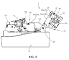
- FIGs. 3 to 5 show a printer according to an embodiment of the present invention.
- the inventive printer is exampled as a dot printer, and may be applied to an electronic cash register or a point of sales system and formed in a drop and printing type or a clamshell type where a roll type paper 130 can be easily loaded in a printer main body 10.
- the dot printer that will be described in this embodiment is exemplary only. That is, a feature of the present invention is applied to not only such a dot printer 1 but also other types of printers such as an inkjet printer and the like.
- FIGs. 3 to 5 show an internal structure of the inventive dot printer 1 by eliminating a cover.
- the dot printer 1 is designed to load the paper 130 in a loading space 15 of the printer main body 10 after a cover frame 20 is opened.
- a printer head 12 is formed on a central upper portion of the printer main body 10 and a ribbon 122 is provided enclosing the printer head 12.
- the cover frame 20 has a rear end that is pivotally connected to the printer main body 10 by a hinge 22 so as to be opened and closed by a vertical pivotal motion.
- a platen 30 is mounted on a front end of the printer main body 10.
- a predetermined gap is defined between the platen 30 and the printer head 12.
- the ribbon 122 is disposed between the platen 30 and the printer head 12.
- a paper path through which the paper 130 passes is defined between the platen 30 and the ribbon 122.
- the platen 30 functions to support the paper in the course of the printing operation performed by a pin 12a of the printer head 12 via the ribbon 122.
- a platen adjusting unit 40 is provided for adjusting a pivotal motion of the platen 30.
- the platen adjusting unit 40 includes a pivot shaft 42 pivotally fixing a front lower portion of the platen 30 on the cover frame 20, an elastic member 45 biasing a rear portion of the platen 30 downward to allow the platen 30 to pivot around the pivot shaft 42, and a gap maintaining unit 50 biasing the rear portion of the platen 40 upward to maintain a predetermined gap T between the platen 30 and the printer head 12.
- the pivot shaft 42 is horizontally inserted through the front lower portion of the platen 30, and the platen 30 is designed having a " "-shaped side section.
- the platen 30 may be formed of metal.
- a plate member 36 formed of metal may be formed on a front surface of the platen 30, which faces the head 12, through an insert injection molding process.
- the pivot shaft 42 is inserted through a lower portion of the plate member 36. Opposite ends of the pivot shaft 42 penetrate through both sidewalls 24a and 24b of the cover frame 20 and locks 42a are fitted around opposite end portions of the pivot shaft 42 to fix the pivot shaft 42. Therefore, the platen 30 is to be pivotally connected to the cover frame 20 around the pivot shaft 42.
- the elastic member 45 biasing the rear portion of the platen 30 downward is formed of a plurality of elastic springs that are vertically disposed at both sides of the platen 30. Upper ends of the springs are hooked on respective rear projections 32 of the platen 30 and lower ends of the springs are hooked on respective projections 26 provided on the both sidewalls 24a and 24b of the cover frame 20. As a result, the rear portion of the platen 30 is biased downward around the pivot shaft 42 unless outer force is applied.
- the gap maintaining unit 50 includes a pair of supporting members 52a and 52b that are projected sideward at a rear portion of the platen 30 and inserted through cutting slits 28 provided on the sidewalls 24a and 24b of the cover frame 20 and a pair of base members 54a and 54b extending upward from an inner portion of the printer main body 10 to support the supporting members 52a and 52b upward.
- the supporting members 52a and 52b are located on lower portions of the respective cutting slots 28 in FIG. 7, since the rear portion of the platen 30 is biased downward by the elastic member 45.
- the supporting members 52a and 52b projected over the cutting slits 28 of the cover frame 20 are supported upward by the base members 54a and 54b to expand the springs, thereby moving the supporting members 52a and 52b upward in the cutting slits 28 as shown in FIG. 8.
- the platen adjusting unit 40 is designed to move the rear portion of the platen downward by the elastic member 45 and to allow the front plate member 36 of the platen to pivot away from the printer head 12 around the pivot shaft 42.
- the supporting members 52a and 52b of the platen 30 supported by the base members 54a and 54b move upward to allow the plate member 36 of the platen 30 to be returned by a pivotal motion, thereby allowing the plate member 36 of the platen closely approach the printer head 12 with a predetermined gap between them.
- the reference numeral 60 that is not described above indicates an assembly of a locking latch and a handle that maintain the closed state of the cover frame 20 on the printer main body 10 and the reference numeral 65 indicates a feed roller advancing the paper.
- the locking latch 60 is first released and the cover frame 20 pivots to be lifted from the printer main body 10.
- the paper loading space 15 in the printer main body 10 is exposed so that the user can easily load the paper in the paper loading space 15 through a drop-in method.
- a front end of the paper 130 is pulled to be drawn toward the printer head 12.
- the cover frame 20 is closed and then moves downward, the rear portion of the platen 30 remains biased rearward by the elastic member 45 until the supporting members 52a and 52b are supported on the base members 54a and 54b.
- the supporting members 52a and 52b contact first the base members 54a and 54b to be supported thereon.
- the rear portion of the platen 30 is lifted while expanding the springs of the elastic member 45. That is, the platen 30 pivots counterclockwise.
- the front plate member 36 of the platen 30 urges the paper 130 to the printer head 12 and the ribbon 122.
- the platen 30 pivots within a range in which the platen 30 is elevated by the base members 54a and 54b.
- the gap T between the platen 30 and the printer head 12 maintains a predetermined value such that the platen 30 can reach the printable position.
- the platen 30 pivots toward the printer head 12 to urge the paper 130 to the printing position. That is, the disposition of the paper 130 between the printer head 12 and the platen 30 between which the ribbon 122 is disposed can be reliably realized.
- the jammed paper when the paper 130 is jammed between the printer head 12 and the platen 30, the jammed paper can be easily removed by simply opening the cover frame 20 from the printer main body 10.
- the above-described operation is realized as the supporting members 52a and 52b move from the upper portion of the cutting slits 28 to the lower portion of the cutting slits 28.
- the cover frame 20 is elastically lifted from the printer main body 10 and the platen 30 pivots away from the head 12, the ribbon 122 and the paper 130, avoiding the confliction with peripheral components.
- the user further lifts the cover frame 20 to remove the jammed paper and exchange the paper.
- the platen adjusting unit 40 allowing the platen 30 to pivot, the jammed paper removal and the paper exchange can be easily performed.
- the loaded paper 130 can be reliably positioned to the printing position between the printer head 12 and the platen 30, between which the ribbon 122 is located, by the pivotal motion of the platen 30, the printing quality can be improved.
- the printer can be inexpensively manufactured while improving the printing quality.
Landscapes
- Handling Of Sheets (AREA)
- Accessory Devices And Overall Control Thereof (AREA)
Applications Claiming Priority (2)
| Application Number | Priority Date | Filing Date | Title |
|---|---|---|---|
| KR1020040026118A KR100557013B1 (ko) | 2004-04-16 | 2004-04-16 | 회전식 플라텐을 구비한 도트 프린터 |
| KR2004026118 | 2004-04-16 |
Publications (2)
| Publication Number | Publication Date |
|---|---|
| EP1586455A2 true EP1586455A2 (de) | 2005-10-19 |
| EP1586455A3 EP1586455A3 (de) | 2006-11-15 |
Family
ID=34940847
Family Applications (1)
| Application Number | Title | Priority Date | Filing Date |
|---|---|---|---|
| EP05252356A Withdrawn EP1586455A3 (de) | 2004-04-16 | 2005-04-15 | Drucker mit schwenkbarem Druckwiderlager |
Country Status (3)
| Country | Link |
|---|---|
| US (1) | US20050232679A1 (de) |
| EP (1) | EP1586455A3 (de) |
| KR (1) | KR100557013B1 (de) |
Cited By (1)
| Publication number | Priority date | Publication date | Assignee | Title |
|---|---|---|---|---|
| EP2335934A4 (de) * | 2008-10-10 | 2012-02-01 | Shandong New Beiyang Inf Tech | Punktmatrixdrucker |
Families Citing this family (12)
| Publication number | Priority date | Publication date | Assignee | Title |
|---|---|---|---|---|
| JP4761465B2 (ja) * | 2006-09-15 | 2011-08-31 | セイコーインスツル株式会社 | サーマルプリンタ |
| JP2008179087A (ja) * | 2007-01-25 | 2008-08-07 | Seiko Instruments Inc | プラテン保持機構および記録ユニット |
| US7635230B2 (en) * | 2007-03-20 | 2009-12-22 | Tsc Auto Id Technology Co., Ltd. | Front cover structure for a label printer |
| JP4967888B2 (ja) * | 2007-07-24 | 2012-07-04 | セイコーエプソン株式会社 | ラベルプリンタ |
| JP5082749B2 (ja) | 2007-10-15 | 2012-11-28 | セイコーエプソン株式会社 | プリンタ |
| JP4998204B2 (ja) | 2007-10-25 | 2012-08-15 | セイコーエプソン株式会社 | インクジェットプリンタ |
| CN101434151B (zh) * | 2007-11-13 | 2010-10-13 | 旭丽电子(广州)有限公司 | 热升华打印机 |
| US8128298B2 (en) * | 2007-12-05 | 2012-03-06 | International Business Machines Corporation | Hinge with sliding pivot transfer |
| JP2012171234A (ja) * | 2011-02-22 | 2012-09-10 | Toshiba Tec Corp | ポータブル型サーマルプリンタ |
| JP2017081015A (ja) * | 2015-10-28 | 2017-05-18 | 富士通コンポーネント株式会社 | プリンタ装置 |
| US11964498B2 (en) | 2019-08-15 | 2024-04-23 | Hewlett-Packard Development Company, L.P. | Printers |
| JP2021094763A (ja) * | 2019-12-16 | 2021-06-24 | ブラザー工業株式会社 | 印刷装置 |
Citations (2)
| Publication number | Priority date | Publication date | Assignee | Title |
|---|---|---|---|---|
| US5887999A (en) | 1997-10-06 | 1999-03-30 | Axiohm Ipb Inc. | Paper loading mechanism |
| US6345782B1 (en) | 1998-10-02 | 2002-02-12 | Seiko Epson Corporation | Printer and control method for the same |
Family Cites Families (7)
| Publication number | Priority date | Publication date | Assignee | Title |
|---|---|---|---|---|
| AU700935B2 (en) * | 1995-11-13 | 1999-01-14 | Zih Corporation | Thermal printer with spring biased drive roller/platen |
| US6118469A (en) * | 1995-11-21 | 2000-09-12 | Seiko Epson Corporation | Thermal printer |
| US6102590A (en) * | 1998-03-12 | 2000-08-15 | International Business Machines Corporation | Cover-platen opening mechanism |
| JP2000094767A (ja) * | 1998-09-25 | 2000-04-04 | Fujitsu Takamisawa Component Ltd | サーマルプリンタ |
| US6435782B1 (en) * | 2000-09-18 | 2002-08-20 | Darrell Hillhouse | Tool for removal of large bolts |
| ES2260356T3 (es) * | 2001-06-25 | 2006-11-01 | Seiko Epson Corporation | Impresora. |
| DE60300868T2 (de) * | 2002-01-18 | 2006-05-11 | Seiko Epson Corp. | Drucker |
-
2004
- 2004-04-16 KR KR1020040026118A patent/KR100557013B1/ko not_active Expired - Fee Related
-
2005
- 2005-04-15 US US11/106,745 patent/US20050232679A1/en not_active Abandoned
- 2005-04-15 EP EP05252356A patent/EP1586455A3/de not_active Withdrawn
Patent Citations (2)
| Publication number | Priority date | Publication date | Assignee | Title |
|---|---|---|---|---|
| US5887999A (en) | 1997-10-06 | 1999-03-30 | Axiohm Ipb Inc. | Paper loading mechanism |
| US6345782B1 (en) | 1998-10-02 | 2002-02-12 | Seiko Epson Corporation | Printer and control method for the same |
Cited By (1)
| Publication number | Priority date | Publication date | Assignee | Title |
|---|---|---|---|---|
| EP2335934A4 (de) * | 2008-10-10 | 2012-02-01 | Shandong New Beiyang Inf Tech | Punktmatrixdrucker |
Also Published As
| Publication number | Publication date |
|---|---|
| EP1586455A3 (de) | 2006-11-15 |
| KR20050100902A (ko) | 2005-10-20 |
| KR100557013B1 (ko) | 2006-03-03 |
| US20050232679A1 (en) | 2005-10-20 |
Similar Documents
| Publication | Publication Date | Title |
|---|---|---|
| EP1586455A2 (de) | Drucker mit schwenkbarem Druckwiderlager | |
| JP3614314B2 (ja) | プリンタ | |
| EP0988985B1 (de) | Thermodrucker | |
| CN105383190B (zh) | 打印单元和热敏打印机 | |
| EP1803579B1 (de) | Bilderzeugungsvorrichtung | |
| EP2042327A2 (de) | Wärmedrucker | |
| CN111070904B (zh) | 热敏打印机 | |
| US6793419B2 (en) | Printer | |
| JP2021126853A (ja) | ローラ支持構造およびプリンタ | |
| EP2368717B1 (de) | Drucker | |
| EP2062736B1 (de) | Drucker | |
| JP2003053999A (ja) | 画像形成装置 | |
| JP3823971B2 (ja) | カバーロック機構付きプリンタ | |
| JP3622856B2 (ja) | プリンタ | |
| US20260021669A1 (en) | Printing apparatus | |
| CN116373462B (zh) | 一种支承组件、耗材单元、打印机芯和打印装置 | |
| WO2014192480A1 (ja) | プリンタ | |
| JP2026034881A (ja) | ヘッドユニット | |
| JPH05147291A (ja) | プリンタ | |
| JPH10278369A (ja) | プリンタのロール紙装填機構 | |
| JP4032951B2 (ja) | プリンタ | |
| JP4075036B2 (ja) | プリンタ | |
| JP2026014545A (ja) | 印刷装置 | |
| US7192206B2 (en) | Image forming apparatus | |
| JP2026013220A (ja) | 記録装置 |
Legal Events
| Date | Code | Title | Description |
|---|---|---|---|
| PUAI | Public reference made under article 153(3) epc to a published international application that has entered the european phase |
Free format text: ORIGINAL CODE: 0009012 |
|
| AK | Designated contracting states |
Kind code of ref document: A2 Designated state(s): AT BE BG CH CY CZ DE DK EE ES FI FR GB GR HU IE IS IT LI LT LU MC NL PL PT RO SE SI SK TR |
|
| AX | Request for extension of the european patent |
Extension state: AL BA HR LV MK YU |
|
| RAP1 | Party data changed (applicant data changed or rights of an application transferred) |
Owner name: BIXOLON CO., LTD. |
|
| PUAL | Search report despatched |
Free format text: ORIGINAL CODE: 0009013 |
|
| AK | Designated contracting states |
Kind code of ref document: A3 Designated state(s): AT BE BG CH CY CZ DE DK EE ES FI FR GB GR HU IE IS IT LI LT LU MC NL PL PT RO SE SI SK TR |
|
| AX | Request for extension of the european patent |
Extension state: AL BA HR LV MK YU |
|
| 17P | Request for examination filed |
Effective date: 20070420 |
|
| AKX | Designation fees paid |
Designated state(s): DE ES FR GB |
|
| 17Q | First examination report despatched |
Effective date: 20070924 |
|
| STAA | Information on the status of an ep patent application or granted ep patent |
Free format text: STATUS: THE APPLICATION IS DEEMED TO BE WITHDRAWN |
|
| 18D | Application deemed to be withdrawn |
Effective date: 20090318 |