EP1586471B1 - Attelage de remorque - Google Patents
Attelage de remorque Download PDFInfo
- Publication number
- EP1586471B1 EP1586471B1 EP05005546A EP05005546A EP1586471B1 EP 1586471 B1 EP1586471 B1 EP 1586471B1 EP 05005546 A EP05005546 A EP 05005546A EP 05005546 A EP05005546 A EP 05005546A EP 1586471 B1 EP1586471 B1 EP 1586471B1
- Authority
- EP
- European Patent Office
- Prior art keywords
- hinge element
- housing
- trailer
- coupling arm
- coupling
- Prior art date
- Legal status (The legal status is an assumption and is not a legal conclusion. Google has not performed a legal analysis and makes no representation as to the accuracy of the status listed.)
- Expired - Lifetime
Links
Images


Classifications
-
- B—PERFORMING OPERATIONS; TRANSPORTING
- B60—VEHICLES IN GENERAL
- B60D—VEHICLE CONNECTIONS
- B60D1/00—Traction couplings; Hitches; Draw-gear; Towing devices
- B60D1/24—Traction couplings; Hitches; Draw-gear; Towing devices characterised by arrangements for particular functions
- B60D1/246—Traction couplings; Hitches; Draw-gear; Towing devices characterised by arrangements for particular functions for actuating the hitch by powered means
-
- B—PERFORMING OPERATIONS; TRANSPORTING
- B60—VEHICLES IN GENERAL
- B60D—VEHICLE CONNECTIONS
- B60D1/00—Traction couplings; Hitches; Draw-gear; Towing devices
- B60D1/01—Traction couplings or hitches characterised by their type
- B60D1/06—Ball-and-socket hitches
-
- B—PERFORMING OPERATIONS; TRANSPORTING
- B60—VEHICLES IN GENERAL
- B60D—VEHICLE CONNECTIONS
- B60D1/00—Traction couplings; Hitches; Draw-gear; Towing devices
- B60D1/48—Traction couplings; Hitches; Draw-gear; Towing devices characterised by the mounting
- B60D1/54—Traction couplings; Hitches; Draw-gear; Towing devices characterised by the mounting collapsible or retractable when not in use, e.g. hide-away hitches
Definitions
- the invention relates to a towing hitch for motor vehicles, in particular for passenger cars, according to the preamble of claim 1, 2 or 3.
- Such a trailer coupling is for example from the DE 100 23 640 A1 known.
- the Drehachsglied is guided in a guide slot which forms a guide element arranged outside the housing for pivoting the Drehachsglieds, and pivots about a pivot axis until a lever arm member abuts against a fixed stop surface.
- the feed device is articulated via the lever arm member eccentrically to the Drehachsglied so that the Drehachsglied pivots when it enters the region of a slot extension of the guide slot.
- the feed device presses the lever arm member firmly against the stop surface, so that there is a tightened position of use.
- a provided with a ball coupling arm of the trailer coupling is driven by a non-visible from outside the motor vehicle rest position in a suitable for attaching a trailer operating position motor or manually driven.
- the ground clearance is sometimes insufficient (depending on the type of vehicle), especially when the vehicle is over a curb.
- the vertically arranged ball bar has a design that can not be integrated into the vehicle in modern vehicles with a particularly low-lying trunk edge.
- the ground clearance is also insufficient in certain embodiments and vehicles.
- the geared motors are exposed to high loads, which makes them expensive and expensive.
- the main pivot bearings are subject to heavy operating forces and must therefore be manufactured in complex and expensive techniques.
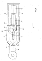
- An exemplary embodiment of the trailer coupling according to the invention consists of a trough-shaped housing 1 with side walls 2, 3, a rear wall 4, a front housing wall 5 and a housing bottom 6 with a slot. 7
- the located in the housing 1 part of the ball arm 9 is designed as Drehachsglied 10.
- the Drehachsglied 10 has in the lower and upper part of a cylindrical shape whose diameter is greater than the inside width of the slot 7.
- the upper part of the Drehachsgliedes 10 has a trapezoidal groove and is described in more detail in Fig. 5.
- an annular groove 18 is arranged, in which a linkage 16 of a linear drive 15 engages.
- the linear drive 15 is pivotally mounted on the rear wall 4 in a bearing 24.
- Fig. 1 shows the trailer hitch in non-use position in a plan view
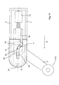
- Fig. 2 in a side view.
- the linear drive 15 is fully retracted, the ball arm 9 is retracted in the slot 7 in the direction of the housing rear wall 4.
- the ball arm 9 is parallel to the longitudinal axis eighth
- Fig. 3 shows the hitch in the position of use in a plan view.
- Fig. 4 in a side view.
- the gate 14 is not shown here to show the position of the Drehachsgliedes in the position of use.
- Fig. 5 shows the ball arm 9 with the Drehachsglied 10 in a plan view, Fig. 6 in a side view.
- the Drehachsglied 10 consists of a lower cylindrical portion 17 and an upper cylindrical portion 19. In the upper part 19, a trapezoidal groove 20 is incorporated. Between the lower and upper part 17, 19 an annular groove 18 is arranged, on which the linear drive 15 engages with the articulation 16.
- Fig. 7 shows the connection between the ball arm 9 and linear drive 15 in an exploded view.
- a U-shaped bearing surface 23 which may be embodied for example as a U-shaped metal strip, comprises the ball arm 9 in the annular groove 18 and forms when merging both parts in the direction of arrows A, B with the bearing surface 22, a circular bearing in which the ball arm 9 about the pivot axis 12 rotate can.
- the connection between the bearing parts 22, 23 is not shown here in detail, it can be realized for example by a screw or rivet connection.
- Fig. 10 the pivoting process is initiated.
- the pin 11 follows the curvature of the link slot 14, thereby the Drehachsglied 10 and thus the ball arm 9 is pivoted about the pivot axis 12 in the direction of arrow D.
- the movements of the Drehachsgliedes 10 are limited in the longitudinal direction of the housing 1 by the linear drive 15 and perpendicular thereto by the voltage applied to the wall of the slot slot 14 pin 11 and by the voltage applied to the rear side wall 2 cylindrical parts 17, 19.
Landscapes
- Engineering & Computer Science (AREA)
- Transportation (AREA)
- Mechanical Engineering (AREA)
- Vehicle Cleaning, Maintenance, Repair, Refitting, And Outriggers (AREA)
- Agricultural Machines (AREA)
- Medicines Containing Plant Substances (AREA)
- Fuel Cell (AREA)
Claims (9)
- Attelage de remorque pour véhicules automobiles, en particulier pour véhicules de tourisme, comportant un bras d'attelage (9), dont une extrémité porte une tête orientée verticalement pour la fixation amovible d'une remorque et dont l'autre extrémité est assemblée de manière fixe à un organe à axe de rotation (10), monté de manière mobile dans un boîtier (1), le bras d'attelage (9) pouvant être déplacé en va-et-vient au moyen d'un dispositif d'avance entre une position de service orientée vers l'arrière et une position hors service agencée davantage à l'avant, le mouvement de réglage au moyen du dispositif d'avance actionné manuellement ou par force étant composé de deux mouvements, caractérisé en ce que l'organe à axe de rotation (10) effectue dans un boîtier (1) un mouvement de translation à partir de la position hors service dans une première partie du mouvement et effectue un pivotement dans une deuxième partie du mouvement, de telle sorte que le bras d'attelage (9), à la fin des deux mouvements qui peuvent se superposer, est amené dans la position de service, en ce que sur l'extrémité supérieure de l'organe à axe de rotation (10) est agencé de manière excentrée un boulon d'entraînement (11) qui se déplace à l'intérieur d'une coulisse (14) sur le boîtier (1) et entraîne l'organe à axe de rotation (10) en rotation autour de son axe médian (12), et en ce que l'organe à axe de rotation (10) pivote jusqu'à ce qu'un évidement (20) sur l'organe à axe de rotation (10) s'engage dans une pièce de forme (21) ajustée à celui-ci sur le boîtier (1) et est ainsi bloqué de telle sorte que l'organe à axe de rotation (10) est maintenu immobile en rotation.
- Attelage de remorque pour véhicules automobiles, en particulier pour véhicules de tourisme, comportant un bras d'attelage (9), dont une extrémité porte une tête orientée verticalement pour la fixation amovible d'une remorque et dont l'autre extrémité est assemblée de manière fixe à un organe à axe de rotation (10), monté de manière mobile dans un boîtier (1), le bras d'attelage (9) pouvant être déplacé en va-et-vient au moyen d'un dispositif d'avance entre une position de service orientée vers l'arrière et une position hors service agencée davantage à l'avant, l'attelage de remorque comportant des éléments de guidage, agencés en dehors du boîtier (1), pour le pivotement du bras d'attelage, et le mouvement de réglage au moyen du dispositif d'avance actionné manuellement ou par force étant composé de deux mouvements, caractérisé en ce que l'organe à axe de rotation (10) effectue dans un boîtier (1) un mouvement de translation à partir de la position hors service dans une première partie du mouvement et effectue un pivotement dans une deuxième partie du mouvement, de telle sorte que le bras d'attelage (9), à la fin des deux mouvements qui peuvent se superposer, est amené dans la position de service, en ce que le bras d'attelage pivote jusqu'à ce qu'un évidement (20) sur l'organe à axe de rotation (10) s'engage dans une pièce de forme (21) ajustée à celui-ci sur le boîtier (1) et est ainsi bloqué de telle sorte que l'organe à axe de rotation (10) est maintenu immobile en rotation.
- Attelage de remorque pour véhicules automobiles, en particulier pour véhicules de tourisme, comportant un bras d'attelage (9), dont une extrémité porte une tête orientée verticalement pour la fixation amovible d'une remorque et dont l'autre extrémité est assemblée de manière fixe à un organe à axe de rotation (10), monté de manière mobile dans un boîtier (1), le bras d'attelage (9) pouvant être déplacé en va-et-vient au moyen d'un dispositif d'avance entre une position de service orientée vers l'arrière et une position hors service agencée davantage à l'avant, et le mouvement de déplacement au moyen du dispositif d'avance actionné manuellement ou par force étant composé de deux mouvements, caractérisé en ce que l'organe à axe de rotation (10) effectue dans un boîtier (1) un mouvement de translation à partir de la position hors service dans une première partie du mouvement et effectue un pivotement dans une deuxième partie du mouvement, de telle sorte que le bras d'attelage (9), à la fin des deux mouvements, est amené dans la position de service, en ce que l'organe à axe de rotation (10) est réalisé en forme de roue dentée et vient buter à la fin de son mouvement linéaire sur une crémaillère qui est montée sur le boîtier et dans laquelle engrène l'organe à axe de rotation en forme de roue dentée, et l'organe à axe de rotation (10) pivote, et en ce que l'organe à axe de rotation (10) pivote jusqu'à ce qu'un évidement (20) sur l'organe à axe de rotation (10) s'engage dans une pièce de forme (21) ajustée à celui-ci sur le boîtier (1) et est ainsi bloqué, de telle sorte que l'organe à axe de rotation (10) est maintenu immobile en rotation.
- Attelage de remorque selon la revendication 1, 2 ou 3, caractérisé en ce que l'évidement (20) et la pièce moulée (21) ont une forme trapézoïdale.
- Attelage de remorque selon la revendication 1, 2 ou 3, caractérisé en ce que le boîtier (1) comporte un fond (6) continu ou au moins deux parties de fond agencées l'une derrière l'autre selon différents angles par rapport à l'horizontale.
- Attelage de remorque selon la revendication 1, 2 ou 3, caractérisé en ce que l'organe à axe de rotation (10) est amené en pivotement sur environ 90 degrés, jusqu'à ce que l'évidement (20) sur l'organe à axe de rotation (10) s'engage dans la pièce moulée (21) sur le boîtier (1).
- Attelage de remorque selon la revendication 1, 2 ou 3, caractérisé en ce que l'organe à axe de rotation (10) est maintenu immobile en rotation dans sa position de service sous l'effet de la pression d'appui du mécanisme de commande (15).
- Attelage de remorque selon la revendication 1, 2 ou 3, caractérisé en ce que l'organe à axe de rotation (10) dans la position de service est fixé contre une paroi latérale arrière (2) et une paroi latérale avant (3) du boîtier (1).
- Attelage de remorque selon la revendication 2, caractérisé en ce que les éléments de guidage agencés en dehors du boîtier (1) comportent des déflecteurs ou des rails.
Applications Claiming Priority (2)
| Application Number | Priority Date | Filing Date | Title |
|---|---|---|---|
| DE202004006204U | 2004-04-17 | ||
| DE202004006204U DE202004006204U1 (de) | 2004-04-17 | 2004-04-17 | Anhängerkupplung |
Publications (2)
| Publication Number | Publication Date |
|---|---|
| EP1586471A1 EP1586471A1 (fr) | 2005-10-19 |
| EP1586471B1 true EP1586471B1 (fr) | 2008-01-30 |
Family
ID=32668344
Family Applications (1)
| Application Number | Title | Priority Date | Filing Date |
|---|---|---|---|
| EP05005546A Expired - Lifetime EP1586471B1 (fr) | 2004-04-17 | 2005-03-15 | Attelage de remorque |
Country Status (3)
| Country | Link |
|---|---|
| EP (1) | EP1586471B1 (fr) |
| AT (1) | ATE385219T1 (fr) |
| DE (2) | DE202004006204U1 (fr) |
Families Citing this family (6)
| Publication number | Priority date | Publication date | Assignee | Title |
|---|---|---|---|---|
| DE102006051096B4 (de) * | 2006-10-25 | 2013-09-12 | Mvg Metallverarbeitungsgesellschaft Mbh | Anhängevorrichtung |
| DE102008043318A1 (de) | 2008-10-30 | 2010-05-12 | Mvg Metallverarbeitungsgesellschaft Mbh | Anhängekupplung |
| DE102017118152B4 (de) | 2017-08-09 | 2020-09-24 | Fac Frank Abels Consulting & Technology Gesellschaft Mbh | Motorisch verschwenkbare Anhängekupplung |
| US11059336B1 (en) * | 2018-04-05 | 2021-07-13 | Charles L. Perry | Retractable hitch adaptor system |
| SE544412C2 (en) * | 2019-03-12 | 2022-05-10 | Brink Towing Systems B V | Retractable towing hook arrangement |
| US12036831B2 (en) * | 2021-01-11 | 2024-07-16 | Ford Global Technologies, Llc | Pivoting vehicle trailer hitch |
Family Cites Families (15)
| Publication number | Priority date | Publication date | Assignee | Title |
|---|---|---|---|---|
| DE3328524A1 (de) * | 1983-08-06 | 1985-02-21 | Daimler-Benz Ag, 7000 Stuttgart | Anhaengerkupplung fuer fahrzeuge |
| DE19654867C2 (de) | 1995-09-13 | 1998-01-22 | Cartron Fahrzeugteile Gmbh | Schwenkbare Anhängerkupplung für Kraftfahrzeuge |
| DE19612959A1 (de) | 1996-04-01 | 1997-10-02 | Oris Fahrzeugteile Riehle H | Anhängekupplung |
| SE509538C2 (sv) | 1997-06-19 | 1999-02-08 | Volvo Ab | Dragkroksanordning för motorfordon |
| DE19826618C2 (de) | 1998-06-17 | 2001-05-03 | Peter Rocca | Anhängekupplung |
| US6447000B1 (en) * | 1999-02-05 | 2002-09-10 | Popup Industries, Inc. | Mechanism for retractable gooseneck hitch ball |
| DE19944264A1 (de) | 1999-09-15 | 2001-03-22 | Jaeger Cartronix Gmbh | Anhängerkupplung mit axialem Verfahrweg |
| DE10004523A1 (de) | 2000-02-02 | 2001-08-09 | Fac Frank Abels Consult & Tech | Anhängerkupplung |
| DE10023641B4 (de) * | 2000-05-13 | 2010-04-29 | Westfalia-Automotive Gmbh | Anhängerkupplung |
| DE10023640C2 (de) | 2000-05-13 | 2003-05-08 | Fac Frank Abels Consult & Tech | Anhängerkupplung |
| DE10104185A1 (de) | 2001-01-23 | 2002-07-25 | Fac Frank Abels Consult & Tech | Anhängerkupplung |
| DE10231221A1 (de) * | 2002-07-11 | 2004-01-29 | Dr.Ing.H.C. F. Porsche Ag | Anhängezugvorrichtung |
| DE10243045B4 (de) * | 2002-09-12 | 2016-01-21 | Westfalia-Automotive Gmbh | Anhängerkupplung |
| DE10243044B4 (de) * | 2002-09-12 | 2016-01-21 | Westfalia-Automotive Gmbh | Anhängerkupplung |
| DE202004006666U1 (de) * | 2003-12-13 | 2004-08-19 | Fac Frank Abels Consulting & Technology Gesellschaft Mbh | Anhängerkupplung |
-
2004
- 2004-04-17 DE DE202004006204U patent/DE202004006204U1/de not_active Expired - Lifetime
-
2005
- 2005-03-15 AT AT05005546T patent/ATE385219T1/de not_active IP Right Cessation
- 2005-03-15 DE DE502005002708T patent/DE502005002708D1/de not_active Expired - Lifetime
- 2005-03-15 EP EP05005546A patent/EP1586471B1/fr not_active Expired - Lifetime
Also Published As
| Publication number | Publication date |
|---|---|
| DE502005002708D1 (de) | 2008-03-20 |
| DE202004006204U1 (de) | 2004-07-01 |
| EP1586471A1 (fr) | 2005-10-19 |
| ATE385219T1 (de) | 2008-02-15 |
Similar Documents
| Publication | Publication Date | Title |
|---|---|---|
| EP1375219B1 (fr) | Store à enrouleur pour lunette arrière avec boîtier levant | |
| EP0850147B2 (fr) | Dispositif d'attelage de remorque pour vehicules automobiles | |
| DE10023640C2 (de) | Anhängerkupplung | |
| EP1880879B1 (fr) | Dispositif d'attelage pivotant pour tracteurs | |
| DE102005007430A1 (de) | Befestigungs- und Positioniervorrichtung für einen Fahrzeugsitz | |
| WO2014001013A1 (fr) | Dispositif de réglage de la position d'un pare-brise | |
| EP1894752A1 (fr) | Attelage de remorque avec crochet extensible et rétractable | |
| DE10243044B4 (de) | Anhängerkupplung | |
| EP1637364B1 (fr) | Attelage de remorque | |
| DE102017203223A1 (de) | Lenkradbaugruppe für ein Kraftfahrzeug | |
| DE10331002A1 (de) | Mitnehmer für einen Kraftfahrzeugfensterheber | |
| EP2289743B1 (fr) | Appui de levage | |
| EP1905617B1 (fr) | Attelage | |
| EP1584500B1 (fr) | Attelage de remorque | |
| EP1586471B1 (fr) | Attelage de remorque | |
| EP1584499B1 (fr) | Attelage de remorque | |
| EP1541385B1 (fr) | Attache remorque | |
| EP1488943B1 (fr) | Dispositif d'attelage motorisé pour véhicules | |
| EP1586470B1 (fr) | Attelage de remorque | |
| DE3003175A1 (de) | Gelenkbeschlag fuer fahrzeugsitze | |
| DE202004006666U1 (de) | Anhängerkupplung | |
| DE10347816B4 (de) | Anhängekupplung mit lastfreier Drehlagereinrichtung | |
| EP1584498B1 (fr) | Attelage de remorque | |
| EP1701870B1 (fr) | Systeme d'essuie-glace pour essuyer un pare-brise | |
| DE10146382A1 (de) | Hubbett für Land-, Wasser-und Luftfahrzeuge |
Legal Events
| Date | Code | Title | Description |
|---|---|---|---|
| PUAI | Public reference made under article 153(3) epc to a published international application that has entered the european phase |
Free format text: ORIGINAL CODE: 0009012 |
|
| AK | Designated contracting states |
Kind code of ref document: A1 Designated state(s): AT BE BG CH CY CZ DE DK EE ES FI FR GB GR HU IE IS IT LI LT LU MC NL PL PT RO SE SI SK TR |
|
| AX | Request for extension of the european patent |
Extension state: AL BA HR LV MK YU |
|
| 17P | Request for examination filed |
Effective date: 20060323 |
|
| AKX | Designation fees paid |
Designated state(s): AT BE BG CH CY CZ DE DK EE ES FI FR GB GR HU IE IS IT LI LT LU MC NL PL PT RO SE SI SK TR |
|
| RAP1 | Party data changed (applicant data changed or rights of an application transferred) |
Owner name: WESTFALIA - AUTOMOTIVE GMBH |
|
| 17Q | First examination report despatched |
Effective date: 20070209 |
|
| GRAP | Despatch of communication of intention to grant a patent |
Free format text: ORIGINAL CODE: EPIDOSNIGR1 |
|
| GRAS | Grant fee paid |
Free format text: ORIGINAL CODE: EPIDOSNIGR3 |
|
| GRAA | (expected) grant |
Free format text: ORIGINAL CODE: 0009210 |
|
| AK | Designated contracting states |
Kind code of ref document: B1 Designated state(s): AT BE BG CH CY CZ DE DK EE ES FI FR GB GR HU IE IS IT LI LT LU MC NL PL PT RO SE SI SK TR |
|
| REG | Reference to a national code |
Ref country code: GB Ref legal event code: FG4D Free format text: NOT ENGLISH |
|
| REG | Reference to a national code |
Ref country code: CH Ref legal event code: EP |
|
| REG | Reference to a national code |
Ref country code: IE Ref legal event code: FG4D Free format text: LANGUAGE OF EP DOCUMENT: GERMAN |
|
| REF | Corresponds to: |
Ref document number: 502005002708 Country of ref document: DE Date of ref document: 20080320 Kind code of ref document: P |
|
| PG25 | Lapsed in a contracting state [announced via postgrant information from national office to epo] |
Ref country code: FI Free format text: LAPSE BECAUSE OF FAILURE TO SUBMIT A TRANSLATION OF THE DESCRIPTION OR TO PAY THE FEE WITHIN THE PRESCRIBED TIME-LIMIT Effective date: 20080130 Ref country code: ES Free format text: LAPSE BECAUSE OF FAILURE TO SUBMIT A TRANSLATION OF THE DESCRIPTION OR TO PAY THE FEE WITHIN THE PRESCRIBED TIME-LIMIT Effective date: 20080511 Ref country code: IS Free format text: LAPSE BECAUSE OF FAILURE TO SUBMIT A TRANSLATION OF THE DESCRIPTION OR TO PAY THE FEE WITHIN THE PRESCRIBED TIME-LIMIT Effective date: 20080530 |
|
| NLV1 | Nl: lapsed or annulled due to failure to fulfill the requirements of art. 29p and 29m of the patents act | ||
| GBV | Gb: ep patent (uk) treated as always having been void in accordance with gb section 77(7)/1977 [no translation filed] | ||
| BERE | Be: lapsed |
Owner name: WESTFALIA - AUTOMOTIVE G.M.B.H. Effective date: 20080331 |
|
| PG25 | Lapsed in a contracting state [announced via postgrant information from national office to epo] |
Ref country code: PL Free format text: LAPSE BECAUSE OF FAILURE TO SUBMIT A TRANSLATION OF THE DESCRIPTION OR TO PAY THE FEE WITHIN THE PRESCRIBED TIME-LIMIT Effective date: 20080130 Ref country code: PT Free format text: LAPSE BECAUSE OF FAILURE TO SUBMIT A TRANSLATION OF THE DESCRIPTION OR TO PAY THE FEE WITHIN THE PRESCRIBED TIME-LIMIT Effective date: 20080630 Ref country code: SI Free format text: LAPSE BECAUSE OF FAILURE TO SUBMIT A TRANSLATION OF THE DESCRIPTION OR TO PAY THE FEE WITHIN THE PRESCRIBED TIME-LIMIT Effective date: 20080130 |
|
| REG | Reference to a national code |
Ref country code: IE Ref legal event code: FD4D |
|
| PG25 | Lapsed in a contracting state [announced via postgrant information from national office to epo] |
Ref country code: SE Free format text: LAPSE BECAUSE OF FAILURE TO SUBMIT A TRANSLATION OF THE DESCRIPTION OR TO PAY THE FEE WITHIN THE PRESCRIBED TIME-LIMIT Effective date: 20080430 Ref country code: CZ Free format text: LAPSE BECAUSE OF FAILURE TO SUBMIT A TRANSLATION OF THE DESCRIPTION OR TO PAY THE FEE WITHIN THE PRESCRIBED TIME-LIMIT Effective date: 20080130 Ref country code: NL Free format text: LAPSE BECAUSE OF FAILURE TO SUBMIT A TRANSLATION OF THE DESCRIPTION OR TO PAY THE FEE WITHIN THE PRESCRIBED TIME-LIMIT Effective date: 20080130 Ref country code: SK Free format text: LAPSE BECAUSE OF FAILURE TO SUBMIT A TRANSLATION OF THE DESCRIPTION OR TO PAY THE FEE WITHIN THE PRESCRIBED TIME-LIMIT Effective date: 20080130 Ref country code: DK Free format text: LAPSE BECAUSE OF FAILURE TO SUBMIT A TRANSLATION OF THE DESCRIPTION OR TO PAY THE FEE WITHIN THE PRESCRIBED TIME-LIMIT Effective date: 20080130 Ref country code: IE Free format text: LAPSE BECAUSE OF FAILURE TO SUBMIT A TRANSLATION OF THE DESCRIPTION OR TO PAY THE FEE WITHIN THE PRESCRIBED TIME-LIMIT Effective date: 20080130 Ref country code: MC Free format text: LAPSE BECAUSE OF NON-PAYMENT OF DUE FEES Effective date: 20080331 |
|
| EN | Fr: translation not filed | ||
| PG25 | Lapsed in a contracting state [announced via postgrant information from national office to epo] |
Ref country code: RO Free format text: LAPSE BECAUSE OF FAILURE TO SUBMIT A TRANSLATION OF THE DESCRIPTION OR TO PAY THE FEE WITHIN THE PRESCRIBED TIME-LIMIT Effective date: 20080130 |
|
| PLBE | No opposition filed within time limit |
Free format text: ORIGINAL CODE: 0009261 |
|
| STAA | Information on the status of an ep patent application or granted ep patent |
Free format text: STATUS: NO OPPOSITION FILED WITHIN TIME LIMIT |
|
| PG25 | Lapsed in a contracting state [announced via postgrant information from national office to epo] |
Ref country code: GB Free format text: LAPSE BECAUSE OF FAILURE TO SUBMIT A TRANSLATION OF THE DESCRIPTION OR TO PAY THE FEE WITHIN THE PRESCRIBED TIME-LIMIT Effective date: 20080130 |
|
| 26N | No opposition filed |
Effective date: 20081031 |
|
| PG25 | Lapsed in a contracting state [announced via postgrant information from national office to epo] |
Ref country code: EE Free format text: LAPSE BECAUSE OF FAILURE TO SUBMIT A TRANSLATION OF THE DESCRIPTION OR TO PAY THE FEE WITHIN THE PRESCRIBED TIME-LIMIT Effective date: 20080130 Ref country code: LT Free format text: LAPSE BECAUSE OF FAILURE TO SUBMIT A TRANSLATION OF THE DESCRIPTION OR TO PAY THE FEE WITHIN THE PRESCRIBED TIME-LIMIT Effective date: 20080130 |
|
| PG25 | Lapsed in a contracting state [announced via postgrant information from national office to epo] |
Ref country code: BE Free format text: LAPSE BECAUSE OF NON-PAYMENT OF DUE FEES Effective date: 20080331 |
|
| PG25 | Lapsed in a contracting state [announced via postgrant information from national office to epo] |
Ref country code: FR Free format text: LAPSE BECAUSE OF FAILURE TO SUBMIT A TRANSLATION OF THE DESCRIPTION OR TO PAY THE FEE WITHIN THE PRESCRIBED TIME-LIMIT Effective date: 20081121 Ref country code: BG Free format text: LAPSE BECAUSE OF FAILURE TO SUBMIT A TRANSLATION OF THE DESCRIPTION OR TO PAY THE FEE WITHIN THE PRESCRIBED TIME-LIMIT Effective date: 20080430 |
|
| PG25 | Lapsed in a contracting state [announced via postgrant information from national office to epo] |
Ref country code: CY Free format text: LAPSE BECAUSE OF FAILURE TO SUBMIT A TRANSLATION OF THE DESCRIPTION OR TO PAY THE FEE WITHIN THE PRESCRIBED TIME-LIMIT Effective date: 20080130 |
|
| PG25 | Lapsed in a contracting state [announced via postgrant information from national office to epo] |
Ref country code: IT Free format text: LAPSE BECAUSE OF FAILURE TO SUBMIT A TRANSLATION OF THE DESCRIPTION OR TO PAY THE FEE WITHIN THE PRESCRIBED TIME-LIMIT Effective date: 20080130 Ref country code: AT Free format text: LAPSE BECAUSE OF NON-PAYMENT OF DUE FEES Effective date: 20080315 |
|
| REG | Reference to a national code |
Ref country code: CH Ref legal event code: PL |
|
| PG25 | Lapsed in a contracting state [announced via postgrant information from national office to epo] |
Ref country code: LI Free format text: LAPSE BECAUSE OF NON-PAYMENT OF DUE FEES Effective date: 20090331 Ref country code: CH Free format text: LAPSE BECAUSE OF NON-PAYMENT OF DUE FEES Effective date: 20090331 |
|
| PG25 | Lapsed in a contracting state [announced via postgrant information from national office to epo] |
Ref country code: LU Free format text: LAPSE BECAUSE OF NON-PAYMENT OF DUE FEES Effective date: 20080315 Ref country code: HU Free format text: LAPSE BECAUSE OF FAILURE TO SUBMIT A TRANSLATION OF THE DESCRIPTION OR TO PAY THE FEE WITHIN THE PRESCRIBED TIME-LIMIT Effective date: 20080731 |
|
| PG25 | Lapsed in a contracting state [announced via postgrant information from national office to epo] |
Ref country code: TR Free format text: LAPSE BECAUSE OF FAILURE TO SUBMIT A TRANSLATION OF THE DESCRIPTION OR TO PAY THE FEE WITHIN THE PRESCRIBED TIME-LIMIT Effective date: 20080130 |
|
| PG25 | Lapsed in a contracting state [announced via postgrant information from national office to epo] |
Ref country code: GR Free format text: LAPSE BECAUSE OF FAILURE TO SUBMIT A TRANSLATION OF THE DESCRIPTION OR TO PAY THE FEE WITHIN THE PRESCRIBED TIME-LIMIT Effective date: 20080501 |
|
| REG | Reference to a national code |
Ref country code: DE Ref legal event code: R082 Ref document number: 502005002708 Country of ref document: DE Representative=s name: BREGENZER, MICHAEL, DIPL.-ING., DE Ref country code: DE Ref legal event code: R082 Ref document number: 502005002708 Country of ref document: DE Representative=s name: PATENTANWAELTE BREGENZER UND REULE PARTNERSCHA, DE |
|
| REG | Reference to a national code |
Ref country code: DE Ref legal event code: R082 Ref document number: 502005002708 Country of ref document: DE Representative=s name: PATENTANWAELTE BREGENZER UND REULE PARTNERSCHA, DE |
|
| PGFP | Annual fee paid to national office [announced via postgrant information from national office to epo] |
Ref country code: DE Payment date: 20220309 Year of fee payment: 18 |
|
| REG | Reference to a national code |
Ref country code: DE Ref legal event code: R119 Ref document number: 502005002708 Country of ref document: DE |
|
| PG25 | Lapsed in a contracting state [announced via postgrant information from national office to epo] |
Ref country code: DE Free format text: LAPSE BECAUSE OF NON-PAYMENT OF DUE FEES Effective date: 20231003 |