EP1586485A2 - Dispositif de blocage en hauteur d'un appui-tête - Google Patents
Dispositif de blocage en hauteur d'un appui-tête Download PDFInfo
- Publication number
- EP1586485A2 EP1586485A2 EP05007941A EP05007941A EP1586485A2 EP 1586485 A2 EP1586485 A2 EP 1586485A2 EP 05007941 A EP05007941 A EP 05007941A EP 05007941 A EP05007941 A EP 05007941A EP 1586485 A2 EP1586485 A2 EP 1586485A2
- Authority
- EP
- European Patent Office
- Prior art keywords
- headrest
- driving gear
- pulley
- gear
- rotational
- Prior art date
- Legal status (The legal status is an assumption and is not a legal conclusion. Google has not performed a legal analysis and makes no representation as to the accuracy of the status listed.)
- Withdrawn
Links
- 238000004804 winding Methods 0.000 claims abstract description 11
- 230000005540 biological transmission Effects 0.000 claims abstract description 10
- 238000006243 chemical reaction Methods 0.000 claims abstract description 8
- 230000007246 mechanism Effects 0.000 description 26
- 238000010276 construction Methods 0.000 description 14
- 230000004308 accommodation Effects 0.000 description 6
- 230000002093 peripheral effect Effects 0.000 description 6
- 230000007423 decrease Effects 0.000 description 4
- 230000002452 interceptive effect Effects 0.000 description 4
- 229920000742 Cotton Polymers 0.000 description 1
- 230000003213 activating effect Effects 0.000 description 1
- 229910003460 diamond Inorganic materials 0.000 description 1
- 239000010432 diamond Substances 0.000 description 1
- 239000006185 dispersion Substances 0.000 description 1
- 230000000694 effects Effects 0.000 description 1
- 238000011031 large-scale manufacturing process Methods 0.000 description 1
- 230000010355 oscillation Effects 0.000 description 1
- 230000000087 stabilizing effect Effects 0.000 description 1
Images


Classifications
-
- B—PERFORMING OPERATIONS; TRANSPORTING
- B60—VEHICLES IN GENERAL
- B60N—SEATS SPECIALLY ADAPTED FOR VEHICLES; VEHICLE PASSENGER ACCOMMODATION NOT OTHERWISE PROVIDED FOR
- B60N2/00—Seats specially adapted for vehicles; Arrangement or mounting of seats in vehicles
- B60N2/02—Seats specially adapted for vehicles; Arrangement or mounting of seats in vehicles the seat or part thereof being movable, e.g. adjustable
- B60N2/04—Seats specially adapted for vehicles; Arrangement or mounting of seats in vehicles the seat or part thereof being movable, e.g. adjustable the whole seat being movable
- B60N2/06—Seats specially adapted for vehicles; Arrangement or mounting of seats in vehicles the seat or part thereof being movable, e.g. adjustable the whole seat being movable slidable
-
- B—PERFORMING OPERATIONS; TRANSPORTING
- B60—VEHICLES IN GENERAL
- B60N—SEATS SPECIALLY ADAPTED FOR VEHICLES; VEHICLE PASSENGER ACCOMMODATION NOT OTHERWISE PROVIDED FOR
- B60N2/00—Seats specially adapted for vehicles; Arrangement or mounting of seats in vehicles
- B60N2/80—Head-rests
- B60N2/806—Head-rests movable or adjustable
- B60N2/809—Head-rests movable or adjustable vertically slidable
- B60N2/812—Head-rests movable or adjustable vertically slidable characterised by their locking devices
- B60N2/821—Head-rests movable or adjustable vertically slidable characterised by their locking devices with continuous positioning
-
- B—PERFORMING OPERATIONS; TRANSPORTING
- B60—VEHICLES IN GENERAL
- B60N—SEATS SPECIALLY ADAPTED FOR VEHICLES; VEHICLE PASSENGER ACCOMMODATION NOT OTHERWISE PROVIDED FOR
- B60N2/00—Seats specially adapted for vehicles; Arrangement or mounting of seats in vehicles
- B60N2/80—Head-rests
- B60N2/806—Head-rests movable or adjustable
- B60N2/809—Head-rests movable or adjustable vertically slidable
- B60N2/829—Head-rests movable or adjustable vertically slidable characterised by their adjusting mechanisms, e.g. electric motors
Definitions
- the present invention relates to a headrest height adjustment device. More particularly, the present invention pertains to a headrest height adjustment device for adjusting the height of a headrest that performs in conjunction with the sliding movement of a seat body.
- Known headrest height adjustment devices are described in DE101 17 322 A1 (Figs. 2-3) and DE198 11 688 C1 (Fig. 3).
- the known headrest height adjustment devices adjust a height of a headrest that performs in conjunction with the sliding movement of a seat body in a longitudinal direction of a vehicle.
- a user e.g., a driver
- the known headrest height adjustment devices described in DE101 17 322 A1 and DE198 11 688 C1 include a mechanism for adjusting a height of a headrest that performs in conjunction with the sliding movement of the seat body as well as a mechanism for manually adjusting a height of a headrest individually, construction of a headrest height adjustment device has become complicated.
- a seatback 91 for a vehicle seat of a general design is configured so as incline towards the back of a vehicle in a longitudinal direction.
- the operational direction of a headrest 92 is determined to be an approximately vertical direction of the vehicle in order to maintain a predetermined constant distance between the headrest 92 and a human body that is occupying the seat.
- the seatback 91 includes a back 91a that is hollowed out in the most forward direction possible.
- a lock release mechanism for releasing the headrest is connected to an operational system (e.g., slide lever) of a seat slide mechanism.
- an operational system e.g., slide lever
- This arrangement is for purposes of stabilizing the adjustment operation of a height of the headrest in conjunction with the sliding movement and involves resetting the height of the headrest to an initial state that has been individually adjusted at the time of a sliding operation. Accordingly, in cases where a headrest height adjustment device is applied to a motor driven (electrically driven type) seat slide mechanism, a dedicated actuator is required for releasing the headrest in synchronization with the timing of activating a motor.
- a clearance between the stay 93 of the headrest and a sliding guide support 94 (shown in Fig. 7) is generally set at a minimum level, and thus sliding resistance between the stay 93 and the sliding guide support 94 becomes substantial. Accordingly, with the construction of the known headrest height adjustment devices described in DE101 17 322 A1 and DE198 11 688 C1 where a biasing force of the spring is used for achieving either an upward or downward operation of the headrest, there is a danger that, a desired operation may not be achievable because of inadequate biasing force resulting from dispersion of sliding resistance in circumstances where the headrest height adjustment device is manufactured on the basis of large scale production.
- the present invention provides a headrest height adjustment device, which includes a base member fixed on a seatback of a seat body, a pulley rotatably supported by the base member, the pulley being rotatable in a first direction by unwinding a first end of a rope member wound around the pulley and by winding a second end of the rope member in conjunction with sliding movement of the seat body either in a forward or rearward direction, and the pulley being rotatable in a second direction by winding the first end of a rope member wound around the pulley and unwinding the second end of the rope member in conjunction with sliding movement of the seat body, a rotational arm rotatably supported by the base member and rotated by the pulley by a rotation transmission member, and a conversion member engaged with the rotational arm for operating a headrest in an upward or downward direction by converting rotational movement of the rotational arm into linear movement.
- the pulley rotates by either unwinding or winding a first end or a second end of a rope member in conjunction with a sliding movement of the seat body in a forward or rearward direction.
- the rotational arm is rotated by means of a rotation transmission member.
- the rotational movement of the rotational arm is converted into the linear movement by means of a conversion member, and the headrest is operated in an upward or downward direction in response to the rotational direction of the rotational arm (i.e., the rotational direction of the pulley).
- the headrest can be selectively operated in an upward or downward direction in accordance with the rotational direction of the pulley.
- the operation of the headrest in conjunction with the sliding movement of the seat body can be stabilized for both in the upward and downward directions.
- a device per se can be reduced in size.
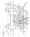
- Fig. 1 is a front view according to an embodiment of the present invention.
- Fig. 2 is a cross-sectional view taken on line II-II in Fig. 1 according to the embodiment of the present invention.
- Fig. 3 is a front view showing operation according to the embodiment of the present invention.
- Figs. 4a-4c are front views showing operation according to the embodiment of the present invention.
- Fig. 5 is a perspective view showing a frame portion of a vehicle seat.
- Fig. 6 is a graph illustrating a relationship between a sliding position and a height of a headrest.
- Fig. 7 is an explanatory view of a known device.
- a vehicle seat 10 includes a pair of lower rails 11a, 11b respectively provided on the left and right sides, as seen when one faces the front of the vehicle, a pair of upper rails 12a, 12b respectively provided on the left and right sides, as seen when one faces the front of the vehicle, a seat cushion frame 13, a seatback frame 14, a headrest 15, and a headrest operating mechanism 20.
- the lower rails 11a, 11b are fixed on a vehicle floor via brackets in an arrangement where a longitudinal direction of the lower rails 11a, 11b corresponds to a longitudinal direction of the vehicle (i.e., in the direction of arrow a in Fig. 5).
- the lower rails 11a, 11b are configured so as to have a U shape in cross section so that the upper part of the lower rails 11a, 11b is open, and an open portion that is opened extends in a longitudinal direction of the lower rails 11a, 11b and forms a slide groove 11c.
- the upper rails 12a, 12b are slidably provided respectively on the lower rails 11a, 11b along the slide grooves 11c in a longitudinal direction.
- the seat cushion frame 13 forms the frame of a seat cushion for constructing a seat surface of a seat body.
- the seat cushion frame 13 includes lower arms 13a, 13b that form a pair in a width direction of the vehicle, and a connection rod 13c that connects the lower arms 13a, 13b.
- the seat cushion frame 13 is supported by the upper rails 12a, 12b via the lower arms 13a, 13b respectively.
- a seatback frame 14 is connected to rear ends of the lower arms 13a, 13b so as to be rotatable about the seat cushion frame 13.
- the seatback frame 14 serves as a frame for a seatback 10a that acts as a seatback of the seat body, and includes side frames 14a, 14b that serve as a pair in a width direction of the vehicle, and an upper pipe 14c that connects top ends of the side frames 14a, 14b.
- Support pipes 14d that form a pair in a width direction of the vehicle are secured to an intermediate portion of the upper pipe 14c.
- the support pipes 14d are fixed to the intermediate portion of the upper pipe 14c in an arrangement such that an axial direction of the support pipes 14d corresponds to an operational direction (i.e., in the direction of arrow b in Fig. 5) of the headrest 15 which is substantially vertical.
- the headrest 15 integrally includes a pair of stays 16 extending coaxially with each of the support pipes 14d.
- the headrest 15 is connected to the seatback frame 14 so to be operated by means of stays 16, 16 respectively inserted into the supports pipes 14d, 14d.
- Each stay 16 is provided with a slide guide support 19 positioned on a seatback 10a above the support pipe 14d.
- the headrest operating mechanism 20 is supported by the upper pipe 14c via a bracket 21 secured to the upper pipe 14c below and between the support pipes 14d.
- a double piped cable 17 i.e., serving as a rope member
- a double piped cable 18 i.e., serving as a rope member
- a cable end 17a of the cable 17 for operating the headrest in an upward direction is fixed on an exterior surface of the first upper rail, and an end 17c of an inner wire 17b protruding from a tip thereof is fixed on an exterior surface of the first lower rail 11b.
- the end 17c is positioned closer to the front of the vehicle than to the cable end 17a (i.e., the direction of arrow a1 in Fig. 5).
- the cable 17 for operating the headrest in an upward direction extends from the first upper rail 12a to the second lower arm 13a in a longitudinal direction of the connection rod 13c, and further extends in a longitudinal direction of the second side frame 14a so that an end of the cable 17 for operating the headrest in an upward direction is connected to the headrest operating mechanism 20.
- a cable end 18a of the cable 18 for operating the headrest in a downward direction is fixed on an exterior surface of the second upper rail 12a, and an end 18c of an inner wire 18b protruding from an end thereof is fixed on an exterior surface of the second lower rail 11a.
- the end 18c is positioned so as to be further to the rear of the vehicle than the cable end 18a (i.e., the direction of arrow a2 in Fig. 5).
- the cable 18 for operating the headrest in a downward direction extends from the second upper rail 12a to the first lower arm 13b, and further extends in a longitudinal direction of the first side frame 14b so that an end of the cable 18 for operating the headrest in a downward direction is connected to the headrest operating mechanism 20.
- the seat body i.e., the seat cushion frame 13
- the seat body i.e., the seat cushion frame 13
- the seat body i.e., the seat cushion frame 13
- slide forward i.e., in the direction of arrow a1
- the headrest operating mechanism 20 moves the headrest 15 in a upward direction (i.e., in the direction of arrow b2) by means of the tension transmitted by the cable 17 for operating the headrest in an upward direction.
- the headrest operating mechanism 20 moves the headrest 15 downward (i.e.. in the direction of arrow b1) by means of the tension transmitted by the cable 18 for operating the headrest in a downward direction.
- Fig. 1 shows a state in which the headrest operating mechanism 20 is positioned at a central position within a moving range in which it performs in conjunction with a sliding movement.
- the headrest operation mechanism 20 includes a base member 22 provided at the bracket 21, a pulley 23, a driving gear 24 (i.e., serving as a rotation transmission member), a cover 25, a lock release lever 26, a rotational arm 27, a fan shaped gear 28 (i.e., serving as a rotation transmission member and a driven gear), a bush 29, and a slider 30 (i.e., serving as a conversion member).
- the base member 22 is configured as a plate that extends in upward and downward directions of the headrest 15 between the stays 16, 16.
- An accommodation recess portion 22a concaved towards the front side (i.e., the bottom side in Fig. 2) at a first side (i.e., the left side in Fig. 2) are formed on a rear surface (i.e., the top side in Fig. 2) of the base member 22.
- Projection walls 22b protruding towards the front side (i.e., the bottom side in Fig. 2) is formed on both sides (i.e., on both the left and right sides in Fig. 2) of the base member 22.
- a guide portion 22c bent outwardly is formed on each of the mutually opposing ends of the projection wall 22b.
- a long bore 22d configured so as to be long in a left and right direction in Fig. 2 is formed at a central portion of the accommodation recess portion 22a.
- a stopper 22e at an upward direction side is formed integrally with the projection wall 22b on the left side in Fig. 1, at a first side (i.e., the top side in Fig. 1) of the base member 22.
- the stopper 22e at the upward direction side is configured into a hook shape that extends diagonally upward towards the center of the base member 22, and a tip of the stopper 22e is bent downward.
- a stopper 22f at a downward direction side is formed integrally with the projection wall 22b at a second side (i.e., at the bottom side in Fig. 1) of the base member 22.
- the stopper 22f at a downward direction side includes a hook shape configuration which extends diagonally downward towards the center of the base member 22, and a tip of the stopper 22f is bent upward.
- the stopper 22e at the upward direction side and the stopper 22f at the downward direction side are formed so that the bent tip ends oppose each other in a direction approximately parallel to an longitudinal direction of the projection wall portion 22b.
- the pulley 23 is accommodated in the accommodation recess portion 22a and supported by the base member 22 so as to be unitarily rotatable with the driving gear 24 relative to the base member 22, and so as to be movable in a longitudinal direction of the long bore 22d.
- the driving gear 24 includes a fixed portion 24a fitted into the pulley 23 so as not to be able to rotate, a first shaft portion 24b and a gear potion 24c that protrudes from the fixed portion 24a to a first side (i.e., the bottom side in Fig.
- the driving gear 24 is unitarily supported with the pulley 23 so as to be rotatable relative to the base member 22, and supported so as to be movable in the longitudinal direction of the long bore 22d.
- a tip of the first shaft portion 24b is penetrated through the long bore 22d so as to be projected to the first side (i.e., the bottom side in Fig. 2).
- a tip of the second shaft portion 24d is penetrated through the center of the pulley 23 so as to be projected to the second side (i.e., the top side in Fig. 2).
- the connections, between, on the one hand, the pulley 23 and, on the other hand, both the cable 17 for operating the headrest in an upward direction and the cable 18 for operating the headrest in a downward direction, will be explained below.
- the cable 17 for operating the headrest in an upward direction extends from a first side (i.e., the right side in Fig. 1) of the base member 22, and a cable end 17d is fixed to the base member 22.
- the cable end 17d is fixed to the base member 22 at a first side of the pulley 23 (i.e., the right side in Fig. 1), and below the center of the pulley 23.
- the inner wire 17b protruding from the tip of the cable end 17d is wound around the pulley 23, clockwise in Fig. 1, and an end 17e of the inner wire 17b is fixed to the pulley 23.
- the cable 18 for operating the headrest in a downward direction extends from a second side (i.e.. the left side in Fig. 1) of the base member 22, and a cable end 18d of the cable 18 is fixed to the base member 22.
- the cable end 18d is fixed to the base member 22 at a second end of the pulley (i.e., the left side in Fig. 1) and below the center of the pulley 23.
- the inner wire 18b protruding from a tip of the cable end 18d is wound around the pulley 23, counterclockwise in Fig. 1, and an end 18e of the inner wire 18b is fixed to the pulley 23.
- the driving gear 24 moves in the longitudinal direction of the long bore 22d at the first shaft portion 24b (shown in Fig. 3). Accordingly, the pulley 23 and the driving gear 24 move in the longitudinal direction of the long bore 22d.
- the cover 25 is secured to an open end of the accommodation recess portion 22a to maintain the pulley 23 accommodated in the accommodation recess portion 22a.
- a long bore 25a which is long in the right-left direction in Fig. 2, is open in the center of the cover 25.
- the long bore 25a is positioned coaxially to the long bore 22d of the base member 22.
- a tip of the second shaft 24d that penetrates through the center of the pulley 23 is positioned therethrough.
- the first shaft portion 24b and the second shaft portion 24d of the driving gear 24, together with the pulley 23 serve as a rotational shaft.
- the long bores 22d, 25a partially serve as bearings of the first and the second shafts 24b, 24d respectively.
- the lock release lever 26 is provided between the base member 22 and the rotational arm 27 at the front side (i.e., the bottom side in Fig. 2) of the base member 22.
- the lock release member 26 is rotatably connected relative to the base member 22 via a hinge pin 31 which penetrates through the base member 22, the lock leaver 26, and the rotational arm 27 and on the intermediate portion of the lock release member 26.
- the lock release lever 26 is pivotally supported by the hinge pin 31 at the opposite side (i.e., the right side in Fig. 2) of the accommodation recess portion 22a.
- the hinge pin 31 is prevented from being pulled out by means of a push nut 32 fitted at a tip portion of the hinge pin 31 protruding to the rear side of the base member 22.
- a cam bore 26a into which a tip of the first shaft portion 24b of the driving gear 24 penetrates through the long bore 22d is formed on the lock release lever 26 at a side of the pulley 23 whereas the rotational center (i.e., the hinge pin 31) is provided at an intermediate portion of the lock release lever 26.
- the cam bore 26a is configured to have a long bore extending in a peripheral direction of the rotational center (i.e., the hinge pin 31), and to define the movement of the first shaft portion 24b in a longitudinal direction in the long bore 22d. Accordingly, the rotational center of the driving gear 24 and the pulley 23 is defined by surrounding the first shaft portion 24b by an inner wall surface of the long bore 22d and by an inner wall surface of the cam bore 26a.
- a distance in a radial direction from the rotational center of the lock release lever 26 to the inner wall surface at a first side in a peripheral direction of the cam bore 26a is determined to be shorter than a distance in a radial direction from the rotational center of the lock release lever 26 to the inner wall surface at a second side in a peripheral direction (i.e., a counterclockwise direction side in Fig. 1) of the cam bore 26a.
- a first end of a tension spring 33 (i.e., serving as a biasing means) is engaged with a bottom portion of the base member 22, and a second end of the tension spring 33 is engaged with the lock release lever 26 so that the lock release lever 26 is biased to rotate, counterclockwise in Fig. 1.
- a radial distance from the rotational center to the driving gear 24 becomes shorter because the first shaft portion 24b (i.e., the driving gear 24) positioned through the cam bore 26a is guided to the inner wall surface of the cam bore 26a at the first side in the peripheral direction.
- the first shaft portion 24b and the second shaft portion 24d contact the inner wall surface at the hinge pin 31 side of the long bores 22d, 25a, respectively.
- a connection portion 26b is formed on the lock release lever 26 at the opposite side of the cam bore 26a relative to the rotational center (i.e., the hinge pin 31) of the lock release lever 26.
- a first end of a rod 34 is connected to the connection portion 26b.
- the rod 34 is extends to the upper pipe 14c side.
- An operational knob 35 which appears above the seatback 10a is fixed on a second end of the rod 34. Accordingly, when the operational knob 35 is pushed down by means of an external force (i.e., external operational force), the connection portion 26b is pushed via the rod 34, and, as shown in Fig. 3, the lock release lever 62 rotates clockwise against the tension spring 33.
- the first shaft portion 24b i.e., the driving gear 24
- the driving gear 24 moves in the longitudinal direction of the long bores 22d, 25a so that the radial distance from the rotational center of the lock release lever 26 becomes longer.
- the first shaft portion 24b and the second shaft portion 42d contact the inner wall surface of the long bores 22d, 25a respectively at the opposite side of the hinge pin.
- the rotational arm 27 rotatably connected to the base member 22 via the hinge pin 31 has an approximately diamond shape.
- the fan shape gear 28 is secured to the central portion of the rear side (i.e., the top in Fig. 2).
- the fan shape gear 28 includes a gear portion 28a extending in a peripheral direction of the rotational center (i.e., the hinge pin 31).
- the gear portion 28a is arranged to be geared with the gear portion 24c when the lock release lever 26 is in the normal lever position and when the radial distance from the rotational center to the driving gear 24 has become short.
- the rotational arm 27 rotates clockwise so as to move upward the tip portion of the rotational arm 27 when the pulley 23 rotates, counterclockwise in Fig. 1.
- the rotational arm 27 rotates counterclockwise so as to move downward the tip portion of the rotational arm 27.
- the gear portion 28a is arranged so as to be released from a geared state with the gear portion 24c when the operational knob 35 is pushed downward and the radial distance from the rotational center to the driving gear 24 has become long (shown in Fig. 3). Accordingly, In these circumstances, the fan shaped gear 28 and the rotational arm 27 rotate freely without interfering with the driving gear 24.
- the rotational arm 27 includes a shaft bore 27b at a tip portion thereof.
- a cylindrical portion of the bush 29 penetrates through the shaft bore 27b, and the rotational arm 27 supports the bush 29.
- the bush 29 includes a slide portion 29a having a block configuration and projected to the front side of the rotational arm 27.
- a tip portion of the bush 29 penetrates the shaft bore 27b and is positioned to be engaged with curved portions of either the upward direction stopper 22e or the downward direction stopper 22f of the base member 22 when the rotational arm 27 rotates.
- the rotation of the rotational arm 27 is restricted by means of the engagement of the tip portion of the bush 29 with curved portions of either the upward direction stopper 22e or the downward direction stopper 22f.
- the rotation of the rotational arm 27 to move the tip side thereof upward is restricted by the engagement of the tip portion of the bush 29 with the curved portion of the upward direction stopper 22e.
- the rotation of the rotational arm 27 to move the tip side thereof downward is restricted by the engagement of the tip portion of the bush 29 with the curved portion of the downward direction stopper 22f.
- the slider 30 is configured to bridge stays 16, 16.
- a holder portion 30a for fixing and holding a tip portion of each of the stays 16 is formed at both sides of slider 30 in a longitudinal direction (i.e., on both the right and left sides in Fig. 2). Accordingly, when either of the headrest 15 and the slider 30 moves upward or downward, the other one of the headrest 15 and the slider 30 also moves in the same direction via the stays 16, 16.
- a pair of guide portions 30b, 30b, into which the guide portions 22c of the base member 22 is positioned is formed on the rear side of the slider 30. Because of engagements between the guide portions 22c and the guide portions 30b, the slider 30 is restricted so as to move only in an upward direction of the headrest 15 relative to the base member 22.
- the slider 30 includes a long bore 30c which is configured so as to be long, in a right-left direction in Fig. 2.
- the slide portion 29a of the bush 29 is slidably provided in the long bore 30c in the longitudinal direction.
- the basic operation of the headrest operating mechanism 20 explained above can be summarized as follows. First, the upward and downward movement of the headrest 15 in conjunction with the sliding movement will be explained.
- a backward direction i.e., in the direction of arrow a2 in Fig. 5
- a distance is increased between the cable end 17a and the end 17c of the cable 17 for operating the headrest in an upward direction
- the inner wire 17b wound around the pulley 23 is thereby pulled, and the pulley 23 rotates, counterclockwise in Fig. 1, along with the driving gear 24.
- the driving gear 24 is guided into the cam bore 26a of the lock release lever 26 at the normal lever position and is positioned closer to the rotational center (i.e., hinge pin 31), and the gear portion 24c is geared with the gear portion 28a of the fan shaped gear 28.
- the rotational arm 27 connected to the driving gear 24 via the fan shaped gear 28 rotates, clockwise in Fig. 1, along with the bush 29.
- the rotational arm 27 rotates in a direction so as to move the tip portion of the rotational ram 27 upward along with the bush 29, within a range restricted by the stopper 22e at the upward direction side.
- the slider 30 is guided by the guide portions 22c, 30b so as to be moved upward. Accordingly, the headrest 15 held at the slider 30 by means of the stays 16 is moved upward. That is, the headrest operating mechanism 20 moves the headrest 15 in an upward direction in conjunction with the backward sliding movement of the seat body.
- the slider 30 is guided by the guide portions 22c, 30b and moved downward. Accordingly, the headrest 15 held at the slider 30 by means of the stays 16 moved downward. In other words, the headrest operating mechanism 20 moves the headrest 15 in a downward direction in conjunction with the forward sliding movement of the seat body.
- the pulley 23 winds the other of the inner wire 17b and the inner wire 18b and this inner wire is returned into the cable at the upper rails 12a, 12b.
- the inner wires 17b, 18b are wound around the pulley 23 in a tense state.
- the rotational arm 27 rotates while sliding the sliding portion 29a into the long bore 30c in accordance with the upward or downward movement of the slider 30, and the headrest 15 can be manually moved upward or downward.
- the lock release lever 26 is returned to the normal lever position by the biasing force of the tension spring 33, and the gear portion 24c of the driving gear 24 is geared with the gear portion 28a of the fan shaped gear 28 at the rotational position of the rotational arm 27 at that time.
- the headrest 15 is held at a position (i.e., height) of the slider 30 depending on the rotational position of the rotational arm 27.
- a point A illustrates a sliding position at the most forward position and a height of the headrest 15 at a bottom end.
- a point B illustrates a state in which the sliding position is a most backward position and a height of the headrest 15 at a top end.
- the bottom end of the height of the headrest 15 is defined by the engagement of the bush 29 to the downward direction stopper 22f of the base member 22 and with further rotation of the rotational arm 27 restricted.
- the top end of a height of the headrest 15 is defined by the engagement of the bush 29 to the upward direction stopper 22e, and with further rotation of the rotational arm 27 restricted.
- a line L represented by a dotted line corresponds to a line connecting point A and point B
- a curve L1 represented by a solid line illustrates a relationship between the sliding position of the seat body and a height of the headrest 15 in conjunction with the operation of the headrest operating mechanism 20.
- the curve L1 corresponds to a sine curve having a line L as a base line.
- the curve L1 crosses the line L at a central point O between point A and point B.
- the relationship between the sliding position of the seat body and a height of the headrest 15 is determined, for example, by determining the ratio of the diameters of the pulley 23 and the driving gear 24 and a gear ratio between the driving gear 24 (i.e., the gear portion 24c) and the fan shaped gear 28 (i.e., the gear portion 28a).
- a pair of pawls 36, 36(i.e., serving as a switching member) and a torsion spring 37 are provided on a back surface of the rotational arm 27.
- a stopper portion 27a is formed on both sides of intermediate portions in a longitudinal direction of the rotational arm 27.
- the pair of pawls 36 is arranged so as to be sandwiched between the stopper portions 27a, 27a positioned at both peripherally exothermal sides of the fan shaped gear 28 and the pawls 36 are rotatably supported by the rotational arm 27.
- Each of the pawls 36, 36 includes a tooth configured portion 36a which is configured in an essentially a gear form of the gear portion 28a, a restriction portion 36b opposing the stopper portion 27a, and an extending portion 36c which extends to a base end of the fan shaped gear 28.
- a rotation of the pawl 36 in a direction where the tooth configured portion 36a is separated from the gear portion 28a is restricted within a range extending from a state where the tooth configured portion 36a is in contact with the fan shaped gear 28 to a state where the restriction portion 36b is in contact with the stopper portion 27a.
- the pawl 36 is arranged so that the tooth configured portion 36a can be deemed to be a gear tooth that is a continuation of a gear tooth at the very end of the gear portion 28a when the pawl 36 is at a position where the restriction portion 36b is in contact with the stopper portion 27a.
- the tooth configured portion 36a in this case, is arranged so as to have approximately the same pitch as the gear teeth of the gear portion 28a.
- the gear portion 24c geared with the gear tooth at the very end of the gear portion 28a is further geared with the tooth configured portion 36a which is arranged as a continuation of the gear portion 28a in accordance with the rotation of the fan shaped gear 28.
- the pawl 36 is arranged so that the tooth configured portion 36a deviates from the rotational locus of the gear portion 24c when the pawl 36 is at a rotational position where the gear configured portion 36a is in contact with the fan shaped gear 28. It goes without saying that the gear portion 28a deviates from the rotational locus of the gear portion 24c. Accordingly, in the foregoing state, the driving gear 24 (i.e., the gear portion 24c) becomes freely rotatable relative to the fan shaped gear 28.
- the torsion spring 37 is secured to the rotational arm 27 at a base end side of the fan shaped gear 28. A pair of free ends of the torsion spring 37 elastically contacts the extended portion 36c of the pawl 36. The torsion spring 37 biases the pawls 36, 36 via the extended portion 36c so that the restriction portion 36b contacts the stopper portion 27a.
- the tooth configured portion 36a of the pawl 36 is arranged as a gear tooth that is a continuation of the gear tooth at the very end of the gear portion 28a (shown in Fig. 4a).
- the driving gear 24 idles because the tooth configured portion 36a deviates from the rotational locus of the gear portion 24c, and the driving gear 24 freely rotates relative to the fan shaped gear 28.
- further rotation of the pulley 23 and the driving gear 24 in conjunction with the backward sliding movement of the seat body is allowed, even after a height of the headrest 15 has reached the top end.
- the tooth configured portion 36a when the pulley 23 and the driving gear 24 rotate in a reverse direction in conjunction with the forward sliding movement at in a state where the gear portion 24c is geared with the tooth configured portion 36a, the tooth configured portion 36a enters the bottom between teeth of the gear portion 24c, and this state is maintained because the restriction portion 36b is in contact with the stopper portion 27a.
- the tooth configured portion 36a functions as a gear tooth arranged as a continuation of a gear tooth at the very end of the gear portion 28a, and the headrest 15 immediately starts to decline from a position corresponding to the top end.
- a height of the headrest 15 is maintained at the top end even if the seat body slides further backward.
- the headrest 15 starts to decline at a time when the sliding movement in the forward direction is initiated irrespective of the sliding position, and thus restarts the operation regarding the sliding movement.
- the pulley 23 rotates so as to either unwind or wind the inner wires 17b, 18b in conjunction with the sliding movement of the seat body in either a forward or backward direction. Thereafter, in accordance with the rotation of the pulley 23, the rotational arm 27 is rotated by means of the driving gear 24 and the fan shaped gear 28. The rotational movement of the rotational arm 27 is converted into linear movement by the slider 30, and the headrest 15 moves upward or downward depending on the rotational direction of the rotational arm 27 (i.e., the rotational direction of the pulley 23.
- the headrest 15 can be selectively moved upward or downward in accordance with the rotational direction of the pulley 23.
- the headrest 15 can be operated in both upward and downward directions stably in conjunction with the sliding movement of the seat body. Because, with the construction of the embodiment of the present invention, it is not necessary to provide an individual construction for operating the headrest in an upward direction or downward, a device can be reduced in size.
- the rotational arm 27 can be rotated by the pulley 23 with a simple construction which includes the driving gear 24 serving as the rotational shaft of the pulley 23, and the fan shaped gear 28 connected by virtue of being geared with the driving gear 24.
- the lock release lever 26 guides the driving gear 24 (i.e., the first shaft portion 24b) via the cam bore 26a, and maintains a state where the driving gear 24 is geared with the fan shaped gear 28. Accordingly, the rotational arm 27 is rotated by the pulley 23 via the driving gear 24 and the fan shaped gear 28.
- the lock release lever 26 guides the driving gear 24 into the cam bore 26a by means of external force from the operational knob 35, and moves the driving gear 24 into a state where the engagement between the fan shaped gear 28 and the driving gear 24 is released.
- the rotation of the rotational arm 27 is lowered without interfering with the pulley 23, or the like.
- the linear movement where the headrest 15 is operated manually in upward and downward directions is allowed as the rotational movement of the rotational arm 27 via the slider 30. That is, by adding external force from the operational knob 35 to the lock release lever 26, the headrest 15 can be manually operated in an upward or downward direction irrespective of the sliding movement of the seat body.
- a geared state between the driving gear 24 and the fan shaped gear 28 provided by means of the lock release lever 26 can be stably maintained.
- the driving gear 24 when the driving gear 24 further rotates beyond the gear tooth at the very end of the gear portion 28a of the fan shaped gear 28, the driving gear 24 is idly operated by means of the pawl 36. Accordingly, even if the pulley 23 (i.e., the driving gear 24) is continuously rotated in accordance with the sliding movement of the seat body after the rotational arm 27 has reached a critical position at which the rotation of the rotational arm 27 is allowed, that is, a critical position (i.e., the top end or bottom end) at which the operation of the headrest in the upward or downward direction is allowed, the height of the headrest 15 can be maintained in the critical position because the driving gear 24 is idling.
- a critical position i.e., the top end or bottom end
- the driving gear 24 rotates in a reverse direction from a tooth gear at the very end of the gear portion 28a of the fan shaped gear 28, the driving gear 24 is geared with the fan shaped gear 28 by means of the pawl 36.
- the headrest 15 reaches a critical position at which the rotation of the rotational arm 27 is allowed, that is, a critical position at which the operation of the headrest 15 in an upward or downward direction is allowed, in accordance with the sliding movement the headrest 15 can be immediately made to start to decline from the critical position in a reverse direction by means of the rotation of the pulley 23 (i.e., the driving gear 24).
- the sliding position of the seat body is not adjusted to be positioned at the most forward position and its vicinity or at the most backward position and its vicinity.
- This arrangement is made because at the aforementioned positions, it is difficult for an occupant to drive because the occupant is positioned either too close to, or too far from, a steering wheel.
- a height of a bottom end of the headrest which is idealistic for an individual with small physical characteristics and a height of a top end of the head rest which is idealistic for an individual with larger physical characteristics be determined at positions before the most forward position and before the most backward position.
- a relationship between the sliding position and a height of the headrest 15 is depicted with a sine curve (curve L1) as shown in Fig. 6.
- a height of the headrest 15 can be made to extend to the bottom end at a position before the sliding position reaches the most forward position, and a height of the headrest 15 can be made to extend to the top end at a position before the sliding position reaches the most backward position.
- the relationship of the sine curve is achieved by converting the rotational movement of the rotational arm 27 (i.e., the fan shaped gear 28) to a linear movement of the slider 30, for example, it is not necessary to provide an individual driving motor or other devices (i.e.. electronic control devices) for controlling the driving motor.
- the embodiment of the present invention may be changed as follows.
- the base member 22 may be fixed to a position other than the seatback frame 14 of the seatback 10a as long as the base member 22 can be fixed firmly.
- the rotational arm 27 and the fan shaped gear 28 may be unitarily formed.
- Constructions other than the double pipe type may be applied for the cable 17 for operating the headrest in an upward direction and the cable 18 for operating the headrest in a downward direction as long as the tension for rotating the pulley is generated in conjunction with the sliding movement.
- other rope members such as wire rope and cotton rope may be adopted as long as sufficient strength can be ensured.
- the inner wires 17b 18b may be connected as one unit as long as being fixed to the pulley 23.
- Means for transmitting rotation between the pulley 23 and the rotational arm 27 is not limited to a geared connection of the driving gear 24 and the fan shaped gear 28.
- the transmission of rotation between the pulley 23 and the rotational arm 27 may be conducted by bridging the pulley 23 and the rotational arm 27 by means of a belt and a rope, or the like.
- a coil spring, a leaf spring, a bar shaped spring, or the like, may be applied to the tension spring 33.
- the pulley rotates by either unwinding or winding a first end or a second end of a rope member in conjunction with a sliding movement of the seat body in a forward or rearward direction.
- the rotational arm is rotated by means of a rotation transmission member.
- the rotational movement of the rotational arm is converted into the linear movement by means of a conversion member, and the headrest is operated in an upward or downward direction in response to the rotational direction of the rotational arm (i.e., the rotational direction of the pulley).
- the headrest can be selectively operated in an upward or downward direction in accordance with the rotational direction of the pulley.
- the operation of the headrest in conjunction with the sliding movement of the seat body can be stabilized for both in the upward and downward directions.
- a device per se can be reduced in size.
- the rotational arm can be rotated by the pulley with a simple construction including a driving gear serving as a rotational shaft of the pulley, and a driven gear which is connected by being geared with the driving gear.
- the lever basically guides the driving gear with the cam bore and maintains the geared state between the driving gear and the driven gear.
- the rotational arm is driven by means of the pulley via the driving gear and the driven gear.
- the lever guides the driving gear with the cam bore by the external force to move the driving gear to be disengaged from the driven gear.
- the rotation of the rotational arm is allowed without interfering with the pulley, or the like. Accordingly, the linear movement when the headrest is manually operated is allowed as the rotational movement of the rotational arm by means of the conversion member. That is, by applying the external force to the lever, the headrest can be manually operated in upward and downward directions irrespective of the sliding movement of the seat body.
- the lever by means of the biasing force of the biasing means, the lever can stably maintain a state where the driving gear and the driven gear are engaged.
- the driving gear when the driving gear is further rotated beyond the gear tooth at the very end of the fan shaped gear, the driving gear is operated idly by means of the switching member. Accordingly, even if the pulley (i.e., the driving gear) is continuously rotated in accordance with the sliding movement after the position of the headrest has reached the critical position at which the operation of the headrest in the upward direction or the downward direction is allowed, a height of the headrest can be maintained at the critical position because the driving gear is idling.
- the pulley i.e., the driving gear
- the driving gear when the driving gear is rotated in a reverse direction from the gear tooth positioned at the very end of the gear portion of the fan shaped gear, the engagement between the driving gear and the fan shaped gear is established by means of the switching member. Accordingly, when the position of the headrest reaches the critical position at which the operation of the headrest in the upward or downward direction is allowed, the headrest can immediately start the operation in the upward or downward direction by means of the rotation of the pulley (i.e., the driving gear) in the reverse direction in accordance with the sliding movement.
- the pulley i.e., the driving gear
- a headrest height adjustment device includes a base member (22) fixed on a seatback (10a) a seat body, a pulley (23) rotatably supported by the base member, the pulley being rotatable in a first direction by unwinding a first end of a rope member wound around the pulley and winding a second end of the rope member in conjunction with sliding movement of the seat body, and the pulley being rotatable in a second direction by winding the first end of a rope member and unwinding the second end of the rope member in conjunction with sliding movement, a rotational arm (27) rotatably supported by the base member and rotated by the pulley by a rotation transmission member (24, 28), and a conversion member (30) engaged with the rotational arm for operating a headrest (15) in an upward or downward direction by converting rotational movement of the rotational arm into linear movement.
Landscapes
- Engineering & Computer Science (AREA)
- Aviation & Aerospace Engineering (AREA)
- Transportation (AREA)
- Mechanical Engineering (AREA)
- Chair Legs, Seat Parts, And Backrests (AREA)
- Seats For Vehicles (AREA)
Applications Claiming Priority (2)
| Application Number | Priority Date | Filing Date | Title |
|---|---|---|---|
| JP2004122173A JP4432591B2 (ja) | 2004-04-16 | 2004-04-16 | ヘッドレスト高さ調整装置 |
| JP2004122173 | 2004-04-16 |
Publications (2)
| Publication Number | Publication Date |
|---|---|
| EP1586485A2 true EP1586485A2 (fr) | 2005-10-19 |
| EP1586485A3 EP1586485A3 (fr) | 2006-06-07 |
Family
ID=34935015
Family Applications (1)
| Application Number | Title | Priority Date | Filing Date |
|---|---|---|---|
| EP05007941A Withdrawn EP1586485A3 (fr) | 2004-04-16 | 2005-04-12 | Dispositif de blocage en hauteur d'un appui-tête |
Country Status (4)
| Country | Link |
|---|---|
| US (1) | US7226124B2 (fr) |
| EP (1) | EP1586485A3 (fr) |
| JP (1) | JP4432591B2 (fr) |
| CN (1) | CN1683183A (fr) |
Cited By (4)
| Publication number | Priority date | Publication date | Assignee | Title |
|---|---|---|---|---|
| DE112007003539B4 (de) * | 2007-06-27 | 2011-06-16 | Toyota Boshoku Kabushiki Kaisha, Kariya-shi | Kabelverbindungsstrukturen für Fahrtzeugsitze mit Kopfstütze |
| WO2012099546A3 (fr) * | 2011-01-17 | 2013-03-14 | Tpv D.D. | Siège d'automobile doté d'un appui-tête automatiquement réglable en hauteur |
| WO2013162480A1 (fr) * | 2012-04-26 | 2013-10-31 | Sieva, Podjetje Za Razvoj In Trzenje V Avtomobilski Industriji, D.O.O. | Siège automobile équipé d'un appuie-tête à réglage en hauteur automatique ou optionnel |
| WO2025220033A1 (fr) * | 2024-04-15 | 2025-10-23 | Prashant Baburao Kale | Dispositif de gestion de position d'appuie-tête de siège automobile |
Families Citing this family (18)
| Publication number | Priority date | Publication date | Assignee | Title |
|---|---|---|---|---|
| JP4857836B2 (ja) * | 2006-03-20 | 2012-01-18 | アイシン精機株式会社 | ヘッドレスト高さ調整装置 |
| CN101074694B (zh) * | 2006-05-18 | 2011-04-20 | 比亚迪股份有限公司 | 座椅头枕调节装置 |
| DE102007029166B4 (de) * | 2007-06-25 | 2011-07-07 | Lear Corp., Mich. | Fahrzeugsitz |
| JP5176476B2 (ja) * | 2007-10-22 | 2013-04-03 | トヨタ紡織株式会社 | 車両用シートのヘッドレスト |
| US8002356B2 (en) * | 2008-11-13 | 2011-08-23 | Bae Industries, Inc. | Pivoting headrest assembly with cam release |
| US8226170B2 (en) * | 2008-11-13 | 2012-07-24 | Bae Industries, Inc. | Pivoting headrest with cable operated release catch |
| CN102387937A (zh) * | 2009-04-23 | 2012-03-21 | 李尔公司 | 具有可调节的头部保护装置组件的座椅组件 |
| KR101565166B1 (ko) * | 2009-09-21 | 2015-11-02 | 주식회사다스 | 시트연동형 헤드레스트장치 |
| US8197007B2 (en) * | 2009-11-03 | 2012-06-12 | Bae Industries, Inc. | Combination pivotal and displaceable headrest assembly incorporated into a vehicle seat |
| DE102011076422A1 (de) * | 2011-05-25 | 2012-11-29 | Lear Corporation | Lösemechanismus für Sitzverstellanordnung |
| JP6283184B2 (ja) * | 2013-09-26 | 2018-02-21 | 日本発條株式会社 | ヘッドレストホルダ、ヘッドレスト支持構造及び車両用シート |
| CN103797980A (zh) * | 2014-03-06 | 2014-05-21 | 星光农机股份有限公司 | 一种联合收割机的驾驶室座椅 |
| JP2015208438A (ja) * | 2014-04-25 | 2015-11-24 | トヨタ紡織株式会社 | 乗物用シート |
| CN106458069B (zh) * | 2014-05-14 | 2019-07-26 | 约翰逊控制技术公司 | 用于头枕的调节机构 |
| KR101762263B1 (ko) * | 2015-12-04 | 2017-08-07 | 현대자동차주식회사 | 헤드레스트와 연동되는 자동차의 전석 제어 시스템 및 그 방법 |
| US10988056B2 (en) | 2017-03-23 | 2021-04-27 | Dorel Juvenile Group, Inc. | Child restraint headrest with side-wing mover |
| CN108836004A (zh) * | 2018-07-27 | 2018-11-20 | 东莞市伟宏五金塑胶制品有限公司 | 头枕同步升降装置 |
| CN116872811B (zh) * | 2023-09-07 | 2023-11-21 | 宁波新华泰模塑电器有限公司 | 一种汽车座椅头枕的自锁装置 |
Citations (2)
| Publication number | Priority date | Publication date | Assignee | Title |
|---|---|---|---|---|
| DE19811688C1 (de) | 1998-03-18 | 1999-09-09 | Keiper Gmbh & Co | Fahrzeugsitz, insbesondere Kraftfahrzeugsitz |
| DE10117322A1 (de) | 2001-01-11 | 2002-07-25 | Webasto Vehicle Sys Int Gmbh | Fahrzeugdach |
Family Cites Families (16)
| Publication number | Priority date | Publication date | Assignee | Title |
|---|---|---|---|---|
| US3065029A (en) * | 1960-11-02 | 1962-11-20 | Spound | Headrest construction |
| US3471198A (en) * | 1967-10-16 | 1969-10-07 | Lear Siegler Inc | Headrest assembly |
| US3499346A (en) * | 1968-04-19 | 1970-03-10 | Takuo Ishida | Indicating system of speed-changing condition for a bicycle |
| DE2925781A1 (de) | 1979-06-26 | 1981-01-15 | Brose & Co Metallwerk Max | Verstellvorrichtung fuer eine kopfstuetze eines kraftfahrzeugsitzes |
| DE3930171C2 (de) * | 1989-09-09 | 1996-02-01 | Keiper Recaro Gmbh Co | Überrollschutz |
| FR2675103B1 (fr) * | 1991-04-15 | 1993-08-06 | Rockwell Abs France | Frein a main pour vehicule. |
| US5292178A (en) * | 1992-07-15 | 1994-03-08 | General Motors Corporation | Front seat for two-door vehicle |
| JPH1071046A (ja) * | 1996-06-26 | 1998-03-17 | Aisin Seiki Co Ltd | シート装置 |
| DE19631843A1 (de) | 1996-08-07 | 1998-02-12 | Bayerische Motoren Werke Ag | Fahrzeugsitz mit einer Kopfstütze |
| AUPO930397A0 (en) * | 1997-09-19 | 1997-10-09 | Henderson's Industries Pty Ltd | Adjustable headrest |
| DE19957793B4 (de) * | 1999-12-01 | 2009-04-09 | Lear Corp., Southfield | Sitz für ein Fortbewegungsmittel |
| DE10005817B4 (de) * | 2000-02-10 | 2004-06-09 | Itw-Ateco Gmbh | Mechanischer Kopfstützeneinzug mit Gedächtnisfunktion |
| EP1315637B1 (fr) * | 2000-09-08 | 2006-05-03 | Intier Automotive Inc. | Ensemble siege a appui-tete autoreglable |
| JP2003093191A (ja) * | 2001-09-25 | 2003-04-02 | Tachi S Co Ltd | ヘッドレストの上下調節装置 |
| JP4430464B2 (ja) * | 2003-11-21 | 2010-03-10 | アイシン精機株式会社 | ヘッドレスト装置 |
| US7140687B2 (en) * | 2004-11-18 | 2006-11-28 | Fisher Dynamics Corporation | Spring-loaded headrest |
-
2004
- 2004-04-16 JP JP2004122173A patent/JP4432591B2/ja not_active Expired - Fee Related
-
2005
- 2005-04-08 US US11/101,499 patent/US7226124B2/en not_active Expired - Fee Related
- 2005-04-12 EP EP05007941A patent/EP1586485A3/fr not_active Withdrawn
- 2005-04-14 CN CNA2005100657480A patent/CN1683183A/zh active Pending
Patent Citations (2)
| Publication number | Priority date | Publication date | Assignee | Title |
|---|---|---|---|---|
| DE19811688C1 (de) | 1998-03-18 | 1999-09-09 | Keiper Gmbh & Co | Fahrzeugsitz, insbesondere Kraftfahrzeugsitz |
| DE10117322A1 (de) | 2001-01-11 | 2002-07-25 | Webasto Vehicle Sys Int Gmbh | Fahrzeugdach |
Cited By (5)
| Publication number | Priority date | Publication date | Assignee | Title |
|---|---|---|---|---|
| DE112007003539B4 (de) * | 2007-06-27 | 2011-06-16 | Toyota Boshoku Kabushiki Kaisha, Kariya-shi | Kabelverbindungsstrukturen für Fahrtzeugsitze mit Kopfstütze |
| US8113577B2 (en) | 2007-06-27 | 2012-02-14 | Toyota Boshoku Kabushiki Kaisha | Cable connection structures |
| WO2012099546A3 (fr) * | 2011-01-17 | 2013-03-14 | Tpv D.D. | Siège d'automobile doté d'un appui-tête automatiquement réglable en hauteur |
| WO2013162480A1 (fr) * | 2012-04-26 | 2013-10-31 | Sieva, Podjetje Za Razvoj In Trzenje V Avtomobilski Industriji, D.O.O. | Siège automobile équipé d'un appuie-tête à réglage en hauteur automatique ou optionnel |
| WO2025220033A1 (fr) * | 2024-04-15 | 2025-10-23 | Prashant Baburao Kale | Dispositif de gestion de position d'appuie-tête de siège automobile |
Also Published As
| Publication number | Publication date |
|---|---|
| JP2005304565A (ja) | 2005-11-04 |
| JP4432591B2 (ja) | 2010-03-17 |
| EP1586485A3 (fr) | 2006-06-07 |
| US7226124B2 (en) | 2007-06-05 |
| US20050231018A1 (en) | 2005-10-20 |
| CN1683183A (zh) | 2005-10-19 |
Similar Documents
| Publication | Publication Date | Title |
|---|---|---|
| US7226124B2 (en) | Headrest height adjustment device | |
| JP4267833B2 (ja) | 機械式ネックレスト引き降ろし装置 | |
| US6364415B1 (en) | Head rest for vehicle seat | |
| JP5098279B2 (ja) | 車両用シート装置 | |
| JP4069672B2 (ja) | シートバーチカル装置 | |
| US20080100115A1 (en) | Seat apparatus | |
| US7066545B2 (en) | Headrest device | |
| WO2006104288A1 (fr) | Dispositif de reglage de hauteur de siege pour automobile | |
| US20060231719A1 (en) | Seat slide apparatus | |
| JP4058546B2 (ja) | 自動車シート | |
| JP4102903B2 (ja) | 原動機付き車両シート | |
| JP5523856B2 (ja) | シートベルト装置 | |
| JP5218405B2 (ja) | ケーブル連結構造 | |
| US9162591B2 (en) | Power return mechanism for seat back | |
| KR102133635B1 (ko) | 좌석용 위치 조절장치 | |
| JP4239688B2 (ja) | ヘッドレスト高さ調整装置 | |
| JP2011130935A (ja) | シートのリクライニング装置 | |
| JP4899205B2 (ja) | 自動車用シートの高さ調整装置 | |
| KR102766086B1 (ko) | 자동차용 암레스트 컨트롤 장치 | |
| JP7192540B2 (ja) | クッションフレーム | |
| JP4534834B2 (ja) | 自動車のシート位置調整装置 | |
| JPS6319372B2 (fr) | ||
| JP2010058534A (ja) | シートベルトバックル装置 | |
| JP5148180B2 (ja) | 運転姿勢調整装置 | |
| KR20040050944A (ko) | 자동차 시트용 헤드레스트의 높이 자동 조절장치 |
Legal Events
| Date | Code | Title | Description |
|---|---|---|---|
| PUAI | Public reference made under article 153(3) epc to a published international application that has entered the european phase |
Free format text: ORIGINAL CODE: 0009012 |
|
| AK | Designated contracting states |
Kind code of ref document: A2 Designated state(s): AT BE BG CH CY CZ DE DK EE ES FI FR GB GR HU IE IS IT LI LT LU MC NL PL PT RO SE SI SK TR |
|
| AX | Request for extension of the european patent |
Extension state: AL BA HR LV MK YU |
|
| PUAL | Search report despatched |
Free format text: ORIGINAL CODE: 0009013 |
|
| AK | Designated contracting states |
Kind code of ref document: A3 Designated state(s): AT BE BG CH CY CZ DE DK EE ES FI FR GB GR HU IE IS IT LI LT LU MC NL PL PT RO SE SI SK TR |
|
| AX | Request for extension of the european patent |
Extension state: AL BA HR LV MK YU |
|
| 17P | Request for examination filed |
Effective date: 20061206 |
|
| AKX | Designation fees paid |
Designated state(s): DE FR GB |
|
| 17Q | First examination report despatched |
Effective date: 20070402 |
|
| GRAP | Despatch of communication of intention to grant a patent |
Free format text: ORIGINAL CODE: EPIDOSNIGR1 |
|
| STAA | Information on the status of an ep patent application or granted ep patent |
Free format text: STATUS: THE APPLICATION IS DEEMED TO BE WITHDRAWN |
|
| 18D | Application deemed to be withdrawn |
Effective date: 20090115 |