EP1586521A1 - Vorrichtung zur entnahme eines stabförmigen werkstückes mit einem breiten ende - Google Patents
Vorrichtung zur entnahme eines stabförmigen werkstückes mit einem breiten ende Download PDFInfo
- Publication number
- EP1586521A1 EP1586521A1 EP03778846A EP03778846A EP1586521A1 EP 1586521 A1 EP1586521 A1 EP 1586521A1 EP 03778846 A EP03778846 A EP 03778846A EP 03778846 A EP03778846 A EP 03778846A EP 1586521 A1 EP1586521 A1 EP 1586521A1
- Authority
- EP
- European Patent Office
- Prior art keywords
- rod
- hopper
- product
- slit
- discharge device
- Prior art date
- Legal status (The legal status is an assumption and is not a legal conclusion. Google has not performed a legal analysis and makes no representation as to the accuracy of the status listed.)
- Granted
Links
Images


Classifications
-
- B—PERFORMING OPERATIONS; TRANSPORTING
- B65—CONVEYING; PACKING; STORING; HANDLING THIN OR FILAMENTARY MATERIAL
- B65G—TRANSPORT OR STORAGE DEVICES, e.g. CONVEYORS FOR LOADING OR TIPPING, SHOP CONVEYOR SYSTEMS OR PNEUMATIC TUBE CONVEYORS
- B65G47/00—Article or material-handling devices associated with conveyors; Methods employing such devices
- B65G47/02—Devices for feeding articles or materials to conveyors
- B65G47/04—Devices for feeding articles or materials to conveyors for feeding articles
- B65G47/12—Devices for feeding articles or materials to conveyors for feeding articles from disorderly-arranged article piles or from loose assemblages of articles
- B65G47/14—Devices for feeding articles or materials to conveyors for feeding articles from disorderly-arranged article piles or from loose assemblages of articles arranging or orientating the articles by mechanical or pneumatic means during feeding
- B65G47/1407—Devices for feeding articles or materials to conveyors for feeding articles from disorderly-arranged article piles or from loose assemblages of articles arranging or orientating the articles by mechanical or pneumatic means during feeding the articles being fed from a container, e.g. a bowl
- B65G47/1414—Devices for feeding articles or materials to conveyors for feeding articles from disorderly-arranged article piles or from loose assemblages of articles arranging or orientating the articles by mechanical or pneumatic means during feeding the articles being fed from a container, e.g. a bowl by means of movement of at least the whole wall of the container
-
- B—PERFORMING OPERATIONS; TRANSPORTING
- B65—CONVEYING; PACKING; STORING; HANDLING THIN OR FILAMENTARY MATERIAL
- B65G—TRANSPORT OR STORAGE DEVICES, e.g. CONVEYORS FOR LOADING OR TIPPING, SHOP CONVEYOR SYSTEMS OR PNEUMATIC TUBE CONVEYORS
- B65G47/00—Article or material-handling devices associated with conveyors; Methods employing such devices
- B65G47/02—Devices for feeding articles or materials to conveyors
- B65G47/04—Devices for feeding articles or materials to conveyors for feeding articles
- B65G47/12—Devices for feeding articles or materials to conveyors for feeding articles from disorderly-arranged article piles or from loose assemblages of articles
- B65G47/14—Devices for feeding articles or materials to conveyors for feeding articles from disorderly-arranged article piles or from loose assemblages of articles arranging or orientating the articles by mechanical or pneumatic means during feeding
- B65G47/1407—Devices for feeding articles or materials to conveyors for feeding articles from disorderly-arranged article piles or from loose assemblages of articles arranging or orientating the articles by mechanical or pneumatic means during feeding the articles being fed from a container, e.g. a bowl
- B65G47/1442—Devices for feeding articles or materials to conveyors for feeding articles from disorderly-arranged article piles or from loose assemblages of articles arranging or orientating the articles by mechanical or pneumatic means during feeding the articles being fed from a container, e.g. a bowl by means of movement of the bottom or a part of the wall of the container
- B65G47/145—Jigging or reciprocating movement
Definitions
- This invention relates to a device for arranging rod-like products in order one end of each of which is larger sized and discharging them, and particularly, to a discharge device optimal for arranging pipet tips in order and discharging them.
- Pipet tips each in the shape of a rod-like product one end of which is larger sized are transported on a tray on which they are longitudinally and laterally arranged and where they take a vertically erected posture. They are provided to an automatic tester in a state of being accommodated in the tray. Since the tray remains behind after the pipet tips are used, the tray has to be discarded. There has been a tremendously large quantity of pipet tips consumed in the entire country. Hence, trays have also been discarded in an extremely great quantity, having resulted in actual circumstances of requirement for high expenses in disposal.
- a discharge device for pipet tips described in JP-A No. 2000-19182 is constructed so that pipet tips fed at random are taken out individually by lifting up a single pipet tip at a time with a conveyor having a belt in an almost vertical posture and the separated pipet tip is dropped down thus fed by the conveyor onto a slope.
- the slope is inclined at a downward gradient toward a slit and the pipet tip drops down into the slit.
- the slit is a clearance that prevents the flange of a pipet tip to pass therethrough. Therefore, a pipet tip is discharged from the slit while taking a posture in which the flange of the pipet tip is caught by the slit.
- the discharge device is complex in structure and high in manufacturing cost.
- An expensive discharge device can be employed as a device for feeding pipet tips fed at random into a tray.
- a complex, expensive mechanism is difficult to be adopted for a tester. This is because the number of testers is higher than the number of devices feeding pipet tips into trays. Therefore, a simple, inexpensive discharge device is required in order not to have to use a tray by installing a discharge device to a tester.
- a pipet tip is dropped down onto a slope, there is a danger that a pipet tip receives a bad influence such as that the shock gives a damage to a pipet tip.
- a discharge device described in JP-A No. 2001-187629 is equipped with a rotary drum feeding pipet tips at random.
- the rotary drum has a scooping trough for pipet tips on the inner surface thereof. While the rotary drum is rotated, pipet tips are lifted up by the scooping trough and thereafter, dropped down from the scooping trough on slide rails. A pipet tip on the slide rails passes through a falling-down guide and then is dropped down at a determined position on the tray.
- the discharge device with this structure is also complex in structure and high in manufacturing cost. In addition, since a pipet tip is dropped down, there is a danger that a pipet tip receives a damage with ease because of the shock.
- the invention has been made in order to solve the faults that the conventional discharge devices have had and it is an important object of the invention to provide a device for discharge a rod-like product one end of which is larger sized, such as a pipet tip, fed at random, capable of arranging rod-like products in specific posture and discharge them therein with a extremely simple structure and a reduced manufacturing cost.
- a discharge device set forth in claim 1 of the invention is directed to a device which discharges a rod-like product W one end of which is larger sized, comprising a hopper 10 being capable of swaying and defining an opening portion 11 at the bottom surface of the hopper 10, extending in the direction of the rotation axis of the swaying motion; a driving mechanism 20 swaying the hopper 10; and a bottom cover 30 closing the opening portion 11 of the swaying hopper 10 so that rod-like products W do not escape therefrom.
- the bottom cover 30 has the upper surface closing the opening portion 11 of the hopper 10 profiled so as to be in conformity with a locus on which the opening portion 11 of the swaying hopper 10 moves and a slit 31 extending in a direction perpendicular to a direction of the swaying motion so as to be opened on the upper surface.
- the slit 31 has a width that does not allow the maximum outer size portion of a rod-like product W to pass therethrough, but lets almost all the rod-like product to pass therethrough.
- the driving mechanism 20 sways the hopper 10 so that the opening portion 11 of the hopper 10 moves along the upper surface of the bottom cover 30 to thereby guide rod-like products W accommodated in the hopper 10 into the slit 31 of the bottom cover 30 and to discharge the rod-like products W from the slit 31 being arranged in order therein.
- a discharge device set forth in claim 2 of the invention vibrates the bottom cover 30 to discharge the rod-like products W guided into the slit 31.
- rubber-like elastic bodies 14 are fixed at the opening portion 11 of the hopper 10 so as to be close to the bottom cover 30.
- a width of the rubber-like elastic bodies 14 fixed at the opening portion 11 of the hopper 10 is defined to have a width in which the end edges thereof get close to the slit 31 when the hopper 10 is inclined.
- inclination plates 15, which are replacements for the rubber-like elastic bodies are connected to the opening portion 11 of the hopper 10. The inclination plates are connected so that the end edges thereof are close to the bottom cover 30.
- elastic bodies 16 are connected to the inclination plates 15 so that the end edges of the inclination plates 15 get close to the bottom cover 30 using the elastic bodies 16.
- a discharge device set forth in claim 13 of the invention is equipped with a removal arm 50 catching and pulling off a pipet tip, by the flange thereof, moved in a piled-up state, wherein rod-like products are pipet tips.
- a discharge device set forth in claim 14 is not only equipped with the removal arm 50, so as to be inclined relative to a fixing portion 35 not swaying together with the hopper 10, but also has an inclination mechanism 52 for inclining the removal arm 50 made up of permanent magnets 53 fixed on the hopper 10 and the removal arm 50 at respective opposite portions thereof.
- the bottom cover 30 is provided with an upward inclined slit 32 catching the flange of a pipet tip piled up on a pipet tip moved in the slit 31 and raising the piled up pipet tip.
- the upward inclined slit 32 is not only inclined at an upward gradient in a moving direction of the pipet tips, but the fore end of the removal arm 50 has also access to the upward inclined slit 32, thereby enabling the piled-up pipet tip moved along the upward inclined slit 32 to be removed.
- a taking device set forth in claim 16 has a clearance 33 through which the flange T of a rod-like product W at the lowest level passes between the fore end of the upward inclined slit 32 and the bottom cover 30 and the clearance 33 is narrower than twice a thickness of the flange T of a rod-like product W.
- a discharge device of the invention is characterized in that rod-like products such as a pipet tip fed at random can be arranged in specific posture and taken out therein with an extremely simple structure and a mechanism capable of reducing a manufacturing cost. This is because the talking-out device sways the hopper and guides the rod-like products into the slit in the bottom cover provided at the opening portion to take out the rod-like products through the slit.
- a discharge device for a rod-like product of the invention with the above construction is further characterized in that rod-like products can be taken-out in arrangement with a specific posture with less of a shock and damage imposed on rod-like products.
- a discharge device of the invention can also arrange rod-like products in order one end of which is larger sized other than a pipet tip.
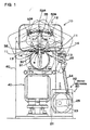
- a discharge device shown in Figs. 1 and 2 includes: a hopper 10 having an opening portion 11 extending in a direction of a swaying rotation center axis at the bottom surface thereof; a driving mechanism 20 swaying the hopper 10; a bottom cover 30 closing the opening portion 11 of the swaying hopper 10; a transport mechanism 40 transporting rod-like products S guided into a slit 31 of the bottom cover 30; and a removal arm 50 removing a rod-like products W in a piled-up state guided into the slit 31.
- the hopper 10 has a supply port 12 through which rod-like products W are fed at the top thereof and the opening portion 11 closed by the bottom cover 30 at the bottom surface thereof.
- the hopper 10 of Fig. 1 has the opening portion 11 in the middle of a flat bottom plate 13.
- the hopper 10 having the flat bottom plate 13 can guide rod-like products W into the slit 13 while preventing bridging of the products W at the slit 31.
- the bottom plate can also be inclined toward the opening portion.
- the hopper 10 shown in the figure has a width of the opening portion 11 narrower than that of the whole hopper 10.
- the hopper 10 can accommodate a great quantity of rod-like products W and guide them into the slit 31 of the bottom cover 30.
- the hopper can also have an opening portion extending all over the bottom.
- a width of the opening portion 11 provided to the hopper 10 is set so that a side edge of the opening portion 11 is in the vicinity of the slit 31 of the bottom cover 30 but does not close the slit 31 when the hopper 10 takes the most inclined posture. Therefore, the width adopts an optimal value taking into consideration the maximum inclination angle to which the hopper 10 sways and a diameter of the bottom cover 30.
- the maximum inclination angle of swaying hopper 10 is preferably about 30 degrees.
- the hopper can also sway in the range of from 5 to 60 degrees and more preferably in the range of from 10 to 45 degrees as a maximum inclination angle.
- a sway cycle of the hopper 10 is preferably about 3 sec.
- the sway cycle is also preferably in the range of 0.5 to 10 sec and more preferably in the range of from 1 to 5 sec. If a cycle of swaying the hopper 10 is increased, rod-like products W move more slowly in the hopper 10; therefore, damage on a rod-like product can be significantly reduced.
- a cycle of the hopper 10 is set to an optimal value taking into consideration a time to discharge a rod-like product W.
- the rod-like products W are guided into the slit 31 toward a direction of the slit 31 formed in the bottom cover 30 in the hopper 10. Since the maximum outer size is larger than a width of the slit 31, the maximum outer size portion (the flange in a case of a pipet tip) gets caught by the slit 31 and a rod-like product W is fed taking a vertical posture therein.
- a slit 331 is, as shown in Fig. 3, in the shape that a width is gradually narrower downward and while the maximum outer size portion of a rod-like product W cannot pass therethrough, almost all the rod-like product W can pass therethrough.
- 330 indicates a bottom plate.
- a length of the hopper 10 is more than that of a rod-like product W in order to be able to direct a rod-like product W toward a direction of the slit 31.
- the hopper 10 is, so as to be swayable, connected to the bottom cover 30 or a frame 60 at one side or both sides thereof. Since the hopper, however, can also sway while being placed on the bottom cover, it is not necessarily required that the hopper 10 is connected to the bottom cover or the frame. Instead, the hopper can be swayed while being supported by a driving mechanism.
- the opening portion 11 of the hopper 10 is closed by the bottom cover 30 in an inclined state of the hopper 10.
- rubber-like elastic bodies 14 are fixed at the opening portion 11 of the hopper 10 so as be close to the bottom cover 30. Not only can the hopper 10 be inclined so that the end edge of the opening portion 11 get close to the bottom cover 30 without a clearance, but the opening portion can also slide smoothly on the surface of the bottom cover 30 with less wear.
- the rubber-like elastic bodies 14 are preferably fixed so as to be exchangeable. The rubber-like elastic bodies 14 can prevent a clearance between the opening portion 11 and the bottom cover 30 from being generated and the rubber-like elastic bodies 14 can be replaced if worn.
- the bottom cover 30 closes the opening portion 11 so that rod-like products W do not escape from the opening portion 11 of the swaying hopper 10. Since the hopper 10 sways, a profile of the upper surface of the bottom cover 30 follows the location of the opening portion 11 of the swaying hopper 10 as it moves and thereby, rod-like products W, even if the hopper 10 sways, do not escape between the opening portion 11 and the bottom cover 30. Since the discharge device of the figure sways the hopper 10 along a circle arc, a profile of the upper surface of the bottom cover 30 has the shape of a circular arc. The bottom cover can also take a profile along an ellipse on the upper surface thereof to close the opening portion of the swaying hopper.
- a discharge device with the bottom cover 30 having a profile of the upper surface in the shape of a circle or an ellipse can move smoothly on the opening portion 11 of the hopper 10.
- the hopper 10 having the opening portion 11 attached with the rubber-like elastic bodies 14 can move the rubber-like elastic bodies 14 smoothly on the upper surface of the bottom cover 30 by sliding thereon.
- the bottom cover can also take a profile of the upper surface in the shape of a polygon so that the opening portion 11 of the swaying hopper is closed without rod-like products escaping from the opening portion 11.
- the bottom cover with the upper surface having a profile in the shape of a polygon changes the width of a clearance between the opening portion and the bottom cover while the hopper sways.
- the hopper can sway so that no rod-like product escape from a clearance.
- a construction is also possible that rubber-like elastic bodies at the opening of the hopper are fixed and the rubber-like elastic bodies are deformed to thereby close a clearance between the opening portion and the bottom cover.
- Narrow, long rod-like products are, in a case, brought into a state of being caught by one another in the vicinity of the slit, that is, a jamming state.
- Jamming of rod-like products can be eliminated by increasing a width of plate-like rubber-like elastic bodies.
- Rubber-like elastic bodies preventing jamming have a width at which the end edge of the rubber-like elastic bodies get close to the slit when the hopper is inclined at the maximum inclination angle.
- the end edges of the rubber-like elastic bodies move closer to the slit each time the hopper is inclined.
- the rubber-like elastic bodies moving closer to the slit move rod-like products which are in a state of being caught by one another with the end edges thereof in order to eliminate the jamming.
- Rubber-like elastic bodies preventing jamming have the end edges thereof in the inside of the slit, at the side edges thereof or outside thereof when the hopper is in the maximum inclination state of being mostly inclined. Rubber-like elastic bodies the end edges of which are moved in the inside of the slit or outside thereof when the hopper is in the maximum inclination state pushes the flanges of rod-like products and guide them in a posture vertical relative to the slit. Therefore, the rubber-like elastic bodies push the flanges of the rod-like products guided into the slit and elastically deforms. Rubber-like elastic bodies with the structure can effectively eliminate jamming of rod-like products in the vicinity of the slit.
- Rubber-like elastic bodies the end edges of which are located outside of the slit when the hopper is at the maximum inclination position do not push the flanges of rod-like products and guide them into the slit. Hence, the rubber-like elastic bodies do not push the flanges of rod-like products and guide them properly into the slit but move only rod-like products in a jamming state in the vicinity of the slit to eliminate jamming.
- elastic bodies with the structure are characterized in that rod-like products guided into the slit can be smoothly moved.
- a hopper can also be connected to inclination plates 415 instead of rubber-like elastic bodies.
- the inclination plates 415 are connected to an opening portion 411 of the hopper 410 so as to be able to be inclined.
- the inclination plates 415 cause the end edges thereof to be close to a bottom cover 430 to seal the hopper 410 so that rod-like products do not escape from the swaying hopper 410.
- the inclination plate 415 forces the fore end thereof to get close to the bottom cover 430 by the weight thereof.
- Elastic bodies 416 are, as shown in the figure, connected to the inclination plates 415 and the end edges of the inclination plates 415 can also be made to get close to the bottom cover 430 by the elastic bodies 416.
- the bottom cover 30 has the slit 31 extending in a direction perpendicular to a direction of a swaying motion of the hopper 10.
- the slit 31 is provided so as to be open on the upper surface of the bottom cover 30.
- the slit 31 has a width that does not allow the maximum outer size portion of a rod-like product W to pass but lets almost all the rod-like piece W, which is the part other than the maximum outer size portion pass. This is because a rod-like product W is put into the slit 31 and moved along the slit 31 in a vertical posture while the flange thereof, which is the maximum outer size portion, is caught by the upper surface of the slit 31 and discharged.
- the slit 31 extends as far as the end portions of the bottom cover 30.
- the driving mechanism 20 sways the hopper 10.
- the driving mechanism 20 in the figure includes: a crank mechanism 22 rotated by a motor 21; and a connecting rod 24 connected to a crank arm 23 of the crank mechanism 22.
- the lower end of the connecting rod 24 is connected to the crank arm 23, while the upper end thereof is connected to one side of the hopper 10 through respective spherical joints 25.
- the motor 21 rotates the crank arm 23
- the connecting rod 24 reciprocates to sway the hopper 10.
- the driving mechanism 20 can sway the hopper 10 in a simple mechanism.
- a discharge device of the invention does not specifically limit a driving mechanism swaying the hopper to the mechanism shown in the figure and any mechanism capable of swaying the hopper; for example a shrinkable cylinder can be connected to the hopper to sway the hopper by stretching or shrinking the cylinder.
- the transport mechanism 40 discharges rod-like products W and guide them into the slit 31 of the bottom cover 30.
- the transport mechanism 40 in the figure is a vibrator vibrating the bottom cover 30.
- the vibrator vibrates the bottom cover 30 so as to move rod-like products W along the slit 31.
- the vibrator can move rod-like products W along the slit 31 in an extremely simple structure.
- the transport mechanism is not specifically limited to a mechanism vibrating the bottom cover.
- Any of mechanisms capable of discharging rod-like products in the slit for example, a structure blowing air to rod-like products in the slit to thereby move them, a structure in which the bottom cover is inclined toward a moving direction of rod-like products, a structure having a conveyor on inner faces of the slit, or the like can be used.
- Rod-like products W such as pipet tips each having a cavity inside thereof are, in some cases, piled up onto each other. This is because a rod-like product W is inserted into the cavity inside another rod-like products W and thereby piling up occurs.
- the discharge device in the figure is equipped with: a removal arm 50 removing a rod-like product moved in a piled-up state; and an upward inclined slit 32.
- the upward inclined slit 32 allows a rod-like product W at the lowest level moved along the slit 31 to pass there under without raising the rod-like product W at the lowest level but raises a rod-like product W moved in a piled up state relative to the rod-like product W at the lowest level.
- the maximum outer size portion of the rod-like products W piled up on the rod-like product W at the lowest level moves through a position higher than the maximum outer size portion of the rod-like product W at the lowest level.
- the upward inclined slit 32 has a clearance 33 between the fore end thereof and the bottom cover 30, through which the maximum outer size portion of the rod-like product W at the lowest level passes.
- the clearance 33 is a clearance through which only the maximum outer size portion of the rod-like product W at the lowest level can pass.
- the clearance 33 is narrower than twice a thickness of the flange T of a rod-like product W.
- the upward inclined slit 32 with a clearance 33 having this width can, as shown in Fig. 5, prevent a rod-like product W at the lowest level having only the flange T of another rod-like product W, without being inserted, piled up on the flange of the rod-like product W of interest from passing therethrough. This is because the clearance 33 does not allow a flange T piled up on the other to pass therethrough.
- the maximum outer size portion of a rod-like product W moved in a state of being piled up on a rod-like product W at the lowest level is gradually raised along the upward inclined slit 32 as it moves.
- the fore end of the upward inclined slit 32 is located lower than the maximum outer size portion of a rod-like product W moved in a state of being piled up on a rod-like product W at the lowest level.
- the upward inclined slit 32 has a width narrower than the maximum outer size portion of a rod-like product W so as to be able to catch and raise the maximum outer size portion of the rod-like product W, wherein the width is able to let almost all of the other portion than the maximum outer size portion pass therethrough.
- the upward inclined slit 32 is inclined at an upward gradient in a moving direction of a rod-like product W.
- Fig. 6 is a perspective view showing the vicinity of the upward inclined slit 32 of the discharge device.
- conical covers 34 are fixed on both sides of the upward inclined slit 32.
- the opening portion 11 of the hopper 10 is gradually larger in width toward one end thereof so as to pass through the conical covers 34.
- a discharge device having the conical covers 34 can eliminate jamming of rod-like products W between the upward inclined slit 32 and the hopper 10.
- the upward inclined slit 32 is equipped with the fore end of a removal arm 50 at a position part way along.
- the removal arm 50 lifts up a rod-like product W and moves it along the upward inclined slit 32 to remove the lifted-up rod-like product W from a rod-like product at the lowest level. That is, the removal arm 50 pulls off the rod-like product W from the rod-like product W at the lowest level by catching the flange, which is the maximum outer portion of a pipet tip as a rod-like product W.
- the discharge device having the upward inclined slit 32 and the removal arm 50 discharges only the rod-like product W at the lowest level which is not in a piled-up state.
- a rod-like product W piled up on the other can also be removed only with the removal arm without using the upward inclined slit.
- the removal arm has its fore ends located at its lowest position so as to be lower than the flange, which is the maximum outer portion of the rod-like product moved in a state of being piled up on the rod-like product at the lowest level.
- the removal arm 50 is installed so as to be inclined relative to a fixed portion 35 not swaying together with the hopper 10.
- the removal arm 50 in the figure is connected to the bottom cover 30 as a fixed portion so as to be inclined relative thereto.
- a support pole 36 extending vertically is fixed to the bottom cover 30 and the removal arm 50 is connected to the support pole 36 so as to be inclinable in a vertical plane.
- the removal arm 50 is connected to the support pole 36 with a rotary shaft 51 interposed in between so as to be inclinable in the vertical plane including the slit 31.
- the removal arm 50 is inclined by an inclination mechanism 52 so that it can pull off a rod-like product W moved in a piled-up state.
- the inclination mechanism 52 in the figure is permanent magnets 53 fixed to the respective opposite portions of the hopper 10 and the removal arm 50.
- a driving arm 54 extends upward from a portion of the removal arm 50 which is connected to the support pole 36 and a first permanent magnet 53A is fixed to the driving arm 54.
- a second permanent magnet 53B is fixed at a position opposite to the first permanent magnet 53A on the hopper 10 while the hopper 10 sways.
- the inclination mechanism 52, while the hopper 10 sways, follows motions in which one of second permanent magnets 53B gets close to the first permanent magnet 53A or gets far away from it.
- the first permanent magnet 53A and a second permanent magnet 53B are facing each other, with an N pole of the former and an S pole of the latter at respective opposite faces, or vice versa.
- the second permanent magnets 53B are, as shown in Fig. 1, placed where the first permanent magnet 53A moves.
- the fore end of the removal arm 50 is inclined so as to lift up the fore end thereof.
- the fore end of the removal arm 50 is inclined so as to move down the fore end thereof by the weight of itself.
- the removal arm can be quickly inclined so as to move down the fore end thereof by a repelling force from a second permanent magnet.
- the inclination mechanism moves upward the fore end when the first permanent magnet passes by a second permanent magnet with a polarity different from that of the first permanent magnet, while moving downward the fore end when the first permanent magnet passes by a second permanent magnet with the same polarity as the first permanent magnet. That is, the removal arm can be quickly inclined by a magnetically attracting force and a magnetically repelling force between permanent magnets.
- the inclination mechanism to incline the removal arm by a magnetic force between permanent magnets can incline the removal arm with an extremely simple structure.
- the removal arm 50 to be inclined by a magnetic force can be inclined so as to move upward the fore end thereof to catch a rod-like product W piled up on a rod-like product W at the lowest level and to pull off the rod-like product W in a piled up state from the other.
- the removal arm 50 as shown in Fig. 7, has a pair of catching tips 50A at the fore end thereof so as to be able to catch a rod-like product W moved in a piled-up state by inclining itself to thereby pull off the rod-like product W.
- a separation width of the catching pieces 50A is narrower than the maximum outer size portion of a rod-like product W, while being almost equal to the width of the upward inclined slit 32 at which almost all the other portion than the maximum outer size portion can pass through.
- the removal arm 50 at the lowest position is located inside of the upward inclined slit 32, that is, lower than the upward inclined slit 32.
- the removal arm 50 moves upward so as to be able to catch a rod-like product W moved in the upward inclined slit 32 and to thereby remove the rod-like product W and thereby, removes a rod-like product W from a rod-like product W at the lowest level.
- the fore end of the removal arm 50 does not catch the rod-like product W at the lowest level moved in the slit 31 but catches a rod-like product W moved in a piled-up state on a rod-like product W at the lowest level.
- a discharge device of the invention can feed rod-like products each having a flange at one end such as a pipet tip used in an analysis on blood, one end of which is larger sized in random posture without being arranged in a tray or the like in order, and can take out the rod-like products in arrangement in order.
Landscapes
- Engineering & Computer Science (AREA)
- Mechanical Engineering (AREA)
- Filling Or Emptying Of Bunkers, Hoppers, And Tanks (AREA)
- Jigging Conveyors (AREA)
- Feeding Of Workpieces (AREA)
- Feeding Of Articles To Conveyors (AREA)
- Cleaning In General (AREA)
- Centrifugal Separators (AREA)
Applications Claiming Priority (3)
| Application Number | Priority Date | Filing Date | Title |
|---|---|---|---|
| JP2003000002 | 2003-01-06 | ||
| JP2003000002 | 2003-01-06 | ||
| PCT/JP2003/015909 WO2004060780A1 (ja) | 2003-01-06 | 2003-12-11 | 一端の外形が大きい棒状ワークの取出装置 |
Publications (3)
| Publication Number | Publication Date |
|---|---|
| EP1586521A1 true EP1586521A1 (de) | 2005-10-19 |
| EP1586521A4 EP1586521A4 (de) | 2006-04-19 |
| EP1586521B1 EP1586521B1 (de) | 2008-06-04 |
Family
ID=32708754
Family Applications (1)
| Application Number | Title | Priority Date | Filing Date |
|---|---|---|---|
| EP03778846A Expired - Lifetime EP1586521B1 (de) | 2003-01-06 | 2003-12-11 | Vorrichtung zur entnahme eines stabförmigen werkstückes mit einem breiten ende |
Country Status (8)
| Country | Link |
|---|---|
| US (1) | US7225913B2 (de) |
| EP (1) | EP1586521B1 (de) |
| JP (1) | JP4378761B2 (de) |
| AT (1) | ATE397561T1 (de) |
| AU (1) | AU2003289044A1 (de) |
| DE (1) | DE60321492D1 (de) |
| ES (1) | ES2307998T3 (de) |
| WO (1) | WO2004060780A1 (de) |
Cited By (1)
| Publication number | Priority date | Publication date | Assignee | Title |
|---|---|---|---|---|
| EP4509440A4 (de) * | 2022-04-11 | 2026-04-01 | Hitachi High Tech Corp | Chipausrichtungsvorrichtung |
Families Citing this family (3)
| Publication number | Priority date | Publication date | Assignee | Title |
|---|---|---|---|---|
| DE102004003037B4 (de) * | 2004-01-20 | 2008-07-03 | Fresenius Kabi Deutschland Gmbh | Vorrichtung zur Übergabe von einen Ausgießer aufweisenden Beuteln |
| US9169070B2 (en) * | 2013-02-14 | 2015-10-27 | Thomas H. Miyashiro | System and apparatus for handling deposit beverage containers |
| CN113651041A (zh) * | 2021-09-23 | 2021-11-16 | 日照华宁机械有限公司 | 一种玉米棒自动整理机 |
Family Cites Families (20)
| Publication number | Priority date | Publication date | Assignee | Title |
|---|---|---|---|---|
| US2977022A (en) * | 1956-11-29 | 1961-03-28 | Atlas Powder Co | Automatic feed apparatus |
| US3623594A (en) * | 1969-10-23 | 1971-11-30 | West Co | Cap-feeding apparatus |
| JPS525701B2 (de) * | 1972-09-11 | 1977-02-16 | ||
| US4034456A (en) * | 1975-12-11 | 1977-07-12 | Bowers Robert H | Machine for providing ball ends on musical instrument strings |
| JPS53166283U (de) * | 1977-06-03 | 1978-12-26 | ||
| US4395625A (en) * | 1981-02-09 | 1983-07-26 | Schutt Donald W | Container counter |
| JPS5834815A (ja) | 1981-08-18 | 1983-03-01 | アメロン (ホンコン) リミテツド | 有機錫重合体、その製造法およびそれを含有する塗料 |
| JPS5834815U (ja) * | 1981-08-31 | 1983-03-07 | 花王株式会社 | 膨出部を有する棒状体の方向整列装置 |
| JPS6132117U (ja) * | 1984-07-30 | 1986-02-26 | 永喜 廣澤 | T形部品収納整列容器 |
| TW348933U (en) * | 1992-12-10 | 1998-12-21 | Matsushita Electric Industrial Co Ltd | Chip component supply equipment |
| JP3301449B2 (ja) * | 1992-12-14 | 2002-07-15 | 日本たばこ産業株式会社 | ロッド材のホッパ装置 |
| IT1262291B (it) * | 1993-08-06 | 1996-06-19 | Sasib Spa | Tramoggia d'alimentazione per prodotti astiformi delicati,in particolare nelle macchine impacchettatrici di sigarette. |
| AU1759297A (en) * | 1996-03-07 | 1997-09-22 | C.A. Greiner & Sohne Gesellschaft M.B.H. | Receiving container for stackable consumable units |
| EP0805620B1 (de) * | 1996-05-01 | 2002-02-20 | Pop Man Corporation | Vorrichtung zum Befördern von Chip-Bauteilen |
| US6334527B1 (en) * | 1997-05-14 | 2002-01-01 | Kyoji Co., Ltd. | Bucket conveyor |
| FR2767517B1 (fr) * | 1997-08-25 | 2001-03-02 | Netra Systems | Convoyeur pour recipients avec guides permettant de limiter le basculement des recipients par rapport a la verticale dans leur direction de transport |
| JP3391707B2 (ja) | 1998-06-29 | 2003-03-31 | 月岡 康信 | ピペットチップセット機 |
| US6432719B1 (en) * | 1999-02-16 | 2002-08-13 | Pe Corporation (Ny) | Matrix storage and dispensing system |
| JP2001026316A (ja) * | 1999-05-12 | 2001-01-30 | Fuji Mach Mfg Co Ltd | 整列供給装置 |
| JP2001187629A (ja) | 1999-12-28 | 2001-07-10 | Daiichi Seimitsu Kk | ピペット用チップの整列送出方法並びにその装置 |
-
2003
- 2003-12-11 AU AU2003289044A patent/AU2003289044A1/en not_active Abandoned
- 2003-12-11 DE DE60321492T patent/DE60321492D1/de not_active Expired - Lifetime
- 2003-12-11 EP EP03778846A patent/EP1586521B1/de not_active Expired - Lifetime
- 2003-12-11 ES ES03778846T patent/ES2307998T3/es not_active Expired - Lifetime
- 2003-12-11 AT AT03778846T patent/ATE397561T1/de not_active IP Right Cessation
- 2003-12-11 JP JP2004564486A patent/JP4378761B2/ja not_active Expired - Fee Related
- 2003-12-11 WO PCT/JP2003/015909 patent/WO2004060780A1/ja not_active Ceased
- 2003-12-11 US US10/541,428 patent/US7225913B2/en not_active Expired - Fee Related
Cited By (1)
| Publication number | Priority date | Publication date | Assignee | Title |
|---|---|---|---|---|
| EP4509440A4 (de) * | 2022-04-11 | 2026-04-01 | Hitachi High Tech Corp | Chipausrichtungsvorrichtung |
Also Published As
| Publication number | Publication date |
|---|---|
| JP4378761B2 (ja) | 2009-12-09 |
| WO2004060780A1 (ja) | 2004-07-22 |
| AU2003289044A1 (en) | 2004-07-29 |
| US20060108197A1 (en) | 2006-05-25 |
| EP1586521B1 (de) | 2008-06-04 |
| DE60321492D1 (de) | 2008-07-17 |
| ATE397561T1 (de) | 2008-06-15 |
| US7225913B2 (en) | 2007-06-05 |
| ES2307998T3 (es) | 2008-12-01 |
| JPWO2004060780A1 (ja) | 2006-05-11 |
| EP1586521A4 (de) | 2006-04-19 |
Similar Documents
| Publication | Publication Date | Title |
|---|---|---|
| DK2019278T3 (en) | Device for loading and unloading an outlet plate by a freeze-drying plant | |
| DK2019277T3 (en) | Device for loading and unloading of an outlet plate of a freeze-drying system and a method for this | |
| US10934098B2 (en) | Methods of conveying and sizing produce | |
| EP0885160A1 (de) | VORRICHTUNG ZUR üBERTRAGUNG VON GEGENSTäNDEN VON EINEM ERSTEN AUF EINEN ZWEITEN FöRDERER | |
| JP2000019182A (ja) | ピペットチップセット機 | |
| CN1015250B (zh) | 一种定向排列容器的堆码机 | |
| EP1586521B1 (de) | Vorrichtung zur entnahme eines stabförmigen werkstückes mit einem breiten ende | |
| CN111856052A (zh) | 一种反应杯加载系统 | |
| CN110542473A (zh) | 一种自动称量方法及系统 | |
| CA1059543A (en) | Magnetic orienting and conveying device for closure flanges | |
| JP6622539B2 (ja) | 容器供給装置 | |
| JP2005254172A (ja) | 青果物の選別装置 | |
| CN222793907U (zh) | 一种移液吸头全自动装盒机器人 | |
| CN221316820U (zh) | 异常蛋出料装置及禽蛋包装设备 | |
| JP3903517B2 (ja) | ゴム製品供給装置 | |
| JP2000019183A (ja) | ピペットチップセット機におけるガイドパイプ | |
| JP3479800B2 (ja) | パーツフィーダ | |
| KR200476357Y1 (ko) | 선별기의 이송장치용 브라켓 | |
| JP4769175B2 (ja) | 極細線材の分離供給装置 | |
| JP3626848B2 (ja) | 農産物の移載装置 | |
| JPH02163212A (ja) | 缶体の分離装置 | |
| JP3050167U (ja) | ゴム製oリング自動搬送装置 | |
| JP2017065882A (ja) | 容器供給装置 | |
| EP3300604A1 (de) | Vorrichtung zur zuführung von fisch in fächer eines förderers einer fischaufbereitungsmaschine | |
| JP2017121965A (ja) | 容器供給装置 |
Legal Events
| Date | Code | Title | Description |
|---|---|---|---|
| PUAI | Public reference made under article 153(3) epc to a published international application that has entered the european phase |
Free format text: ORIGINAL CODE: 0009012 |
|
| 17P | Request for examination filed |
Effective date: 20050726 |
|
| AK | Designated contracting states |
Kind code of ref document: A1 Designated state(s): AT BE BG CH CY CZ DE DK EE ES FI FR GB GR HU IE IT LI LU MC NL PT RO SE SI SK TR |
|
| AX | Request for extension of the european patent |
Extension state: AL LT LV MK |
|
| A4 | Supplementary search report drawn up and despatched |
Effective date: 20060306 |
|
| RIC1 | Information provided on ipc code assigned before grant |
Ipc: B65G 65/40 20060101AFI20040723BHEP Ipc: B65G 47/14 20060101ALI20060228BHEP |
|
| DAX | Request for extension of the european patent (deleted) | ||
| 17Q | First examination report despatched |
Effective date: 20060712 |
|
| RAP1 | Party data changed (applicant data changed or rights of an application transferred) |
Owner name: MIRACA HOLDINGS, INC |
|
| RAP1 | Party data changed (applicant data changed or rights of an application transferred) |
Owner name: FUJIREBIO INC. |
|
| GRAC | Information related to communication of intention to grant a patent modified |
Free format text: ORIGINAL CODE: EPIDOSCIGR1 |
|
| GRAP | Despatch of communication of intention to grant a patent |
Free format text: ORIGINAL CODE: EPIDOSNIGR1 |
|
| GRAC | Information related to communication of intention to grant a patent modified |
Free format text: ORIGINAL CODE: EPIDOSCIGR1 |
|
| GRAS | Grant fee paid |
Free format text: ORIGINAL CODE: EPIDOSNIGR3 |
|
| GRAA | (expected) grant |
Free format text: ORIGINAL CODE: 0009210 |
|
| GRAL | Information related to payment of fee for publishing/printing deleted |
Free format text: ORIGINAL CODE: EPIDOSDIGR3 |
|
| GRAS | Grant fee paid |
Free format text: ORIGINAL CODE: EPIDOSNIGR3 |
|
| AK | Designated contracting states |
Kind code of ref document: B1 Designated state(s): AT BE BG CH CY CZ DE DK EE ES FI FR GB GR HU IE IT LI LU MC NL PT RO SE SI SK TR |
|
| REG | Reference to a national code |
Ref country code: GB Ref legal event code: FG4D |
|
| REG | Reference to a national code |
Ref country code: CH Ref legal event code: EP |
|
| REF | Corresponds to: |
Ref document number: 60321492 Country of ref document: DE Date of ref document: 20080717 Kind code of ref document: P |
|
| REG | Reference to a national code |
Ref country code: IE Ref legal event code: FG4D |
|
| PG25 | Lapsed in a contracting state [announced via postgrant information from national office to epo] |
Ref country code: FI Free format text: LAPSE BECAUSE OF FAILURE TO SUBMIT A TRANSLATION OF THE DESCRIPTION OR TO PAY THE FEE WITHIN THE PRESCRIBED TIME-LIMIT Effective date: 20080604 Ref country code: SI Free format text: LAPSE BECAUSE OF FAILURE TO SUBMIT A TRANSLATION OF THE DESCRIPTION OR TO PAY THE FEE WITHIN THE PRESCRIBED TIME-LIMIT Effective date: 20080604 |
|
| PG25 | Lapsed in a contracting state [announced via postgrant information from national office to epo] |
Ref country code: AT Free format text: LAPSE BECAUSE OF FAILURE TO SUBMIT A TRANSLATION OF THE DESCRIPTION OR TO PAY THE FEE WITHIN THE PRESCRIBED TIME-LIMIT Effective date: 20080604 Ref country code: NL Free format text: LAPSE BECAUSE OF FAILURE TO SUBMIT A TRANSLATION OF THE DESCRIPTION OR TO PAY THE FEE WITHIN THE PRESCRIBED TIME-LIMIT Effective date: 20080604 |
|
| NLV1 | Nl: lapsed or annulled due to failure to fulfill the requirements of art. 29p and 29m of the patents act | ||
| REG | Reference to a national code |
Ref country code: ES Ref legal event code: FG2A Ref document number: 2307998 Country of ref document: ES Kind code of ref document: T3 |
|
| PG25 | Lapsed in a contracting state [announced via postgrant information from national office to epo] |
Ref country code: SE Free format text: LAPSE BECAUSE OF FAILURE TO SUBMIT A TRANSLATION OF THE DESCRIPTION OR TO PAY THE FEE WITHIN THE PRESCRIBED TIME-LIMIT Effective date: 20080904 Ref country code: PT Free format text: LAPSE BECAUSE OF FAILURE TO SUBMIT A TRANSLATION OF THE DESCRIPTION OR TO PAY THE FEE WITHIN THE PRESCRIBED TIME-LIMIT Effective date: 20081104 Ref country code: CZ Free format text: LAPSE BECAUSE OF FAILURE TO SUBMIT A TRANSLATION OF THE DESCRIPTION OR TO PAY THE FEE WITHIN THE PRESCRIBED TIME-LIMIT Effective date: 20080604 |
|
| PG25 | Lapsed in a contracting state [announced via postgrant information from national office to epo] |
Ref country code: RO Free format text: LAPSE BECAUSE OF FAILURE TO SUBMIT A TRANSLATION OF THE DESCRIPTION OR TO PAY THE FEE WITHIN THE PRESCRIBED TIME-LIMIT Effective date: 20080604 Ref country code: SK Free format text: LAPSE BECAUSE OF FAILURE TO SUBMIT A TRANSLATION OF THE DESCRIPTION OR TO PAY THE FEE WITHIN THE PRESCRIBED TIME-LIMIT Effective date: 20080604 Ref country code: BE Free format text: LAPSE BECAUSE OF FAILURE TO SUBMIT A TRANSLATION OF THE DESCRIPTION OR TO PAY THE FEE WITHIN THE PRESCRIBED TIME-LIMIT Effective date: 20080604 |
|
| PLBE | No opposition filed within time limit |
Free format text: ORIGINAL CODE: 0009261 |
|
| STAA | Information on the status of an ep patent application or granted ep patent |
Free format text: STATUS: NO OPPOSITION FILED WITHIN TIME LIMIT |
|
| PG25 | Lapsed in a contracting state [announced via postgrant information from national office to epo] |
Ref country code: BG Free format text: LAPSE BECAUSE OF FAILURE TO SUBMIT A TRANSLATION OF THE DESCRIPTION OR TO PAY THE FEE WITHIN THE PRESCRIBED TIME-LIMIT Effective date: 20080904 Ref country code: DK Free format text: LAPSE BECAUSE OF FAILURE TO SUBMIT A TRANSLATION OF THE DESCRIPTION OR TO PAY THE FEE WITHIN THE PRESCRIBED TIME-LIMIT Effective date: 20080604 Ref country code: EE Free format text: LAPSE BECAUSE OF FAILURE TO SUBMIT A TRANSLATION OF THE DESCRIPTION OR TO PAY THE FEE WITHIN THE PRESCRIBED TIME-LIMIT Effective date: 20080604 |
|
| 26N | No opposition filed |
Effective date: 20090305 |
|
| PG25 | Lapsed in a contracting state [announced via postgrant information from national office to epo] |
Ref country code: MC Free format text: LAPSE BECAUSE OF NON-PAYMENT OF DUE FEES Effective date: 20081231 |
|
| REG | Reference to a national code |
Ref country code: CH Ref legal event code: PL |
|
| REG | Reference to a national code |
Ref country code: IE Ref legal event code: MM4A |
|
| PG25 | Lapsed in a contracting state [announced via postgrant information from national office to epo] |
Ref country code: CH Free format text: LAPSE BECAUSE OF NON-PAYMENT OF DUE FEES Effective date: 20081231 Ref country code: LI Free format text: LAPSE BECAUSE OF NON-PAYMENT OF DUE FEES Effective date: 20081231 Ref country code: IE Free format text: LAPSE BECAUSE OF NON-PAYMENT OF DUE FEES Effective date: 20081211 |
|
| PG25 | Lapsed in a contracting state [announced via postgrant information from national office to epo] |
Ref country code: CY Free format text: LAPSE BECAUSE OF FAILURE TO SUBMIT A TRANSLATION OF THE DESCRIPTION OR TO PAY THE FEE WITHIN THE PRESCRIBED TIME-LIMIT Effective date: 20080604 Ref country code: HU Free format text: LAPSE BECAUSE OF FAILURE TO SUBMIT A TRANSLATION OF THE DESCRIPTION OR TO PAY THE FEE WITHIN THE PRESCRIBED TIME-LIMIT Effective date: 20081205 Ref country code: LU Free format text: LAPSE BECAUSE OF NON-PAYMENT OF DUE FEES Effective date: 20081211 |
|
| PG25 | Lapsed in a contracting state [announced via postgrant information from national office to epo] |
Ref country code: TR Free format text: LAPSE BECAUSE OF FAILURE TO SUBMIT A TRANSLATION OF THE DESCRIPTION OR TO PAY THE FEE WITHIN THE PRESCRIBED TIME-LIMIT Effective date: 20080604 |
|
| PG25 | Lapsed in a contracting state [announced via postgrant information from national office to epo] |
Ref country code: GR Free format text: LAPSE BECAUSE OF FAILURE TO SUBMIT A TRANSLATION OF THE DESCRIPTION OR TO PAY THE FEE WITHIN THE PRESCRIBED TIME-LIMIT Effective date: 20080905 |
|
| REG | Reference to a national code |
Ref country code: FR Ref legal event code: CA Effective date: 20130719 |
|
| PGFP | Annual fee paid to national office [announced via postgrant information from national office to epo] |
Ref country code: DE Payment date: 20141202 Year of fee payment: 12 Ref country code: GB Payment date: 20141210 Year of fee payment: 12 Ref country code: ES Payment date: 20141111 Year of fee payment: 12 |
|
| PGFP | Annual fee paid to national office [announced via postgrant information from national office to epo] |
Ref country code: FR Payment date: 20141208 Year of fee payment: 12 |
|
| PGFP | Annual fee paid to national office [announced via postgrant information from national office to epo] |
Ref country code: IT Payment date: 20141126 Year of fee payment: 12 |
|
| REG | Reference to a national code |
Ref country code: DE Ref legal event code: R119 Ref document number: 60321492 Country of ref document: DE |
|
| GBPC | Gb: european patent ceased through non-payment of renewal fee |
Effective date: 20151211 |
|
| REG | Reference to a national code |
Ref country code: FR Ref legal event code: ST Effective date: 20160831 |
|
| PG25 | Lapsed in a contracting state [announced via postgrant information from national office to epo] |
Ref country code: GB Free format text: LAPSE BECAUSE OF NON-PAYMENT OF DUE FEES Effective date: 20151211 Ref country code: DE Free format text: LAPSE BECAUSE OF NON-PAYMENT OF DUE FEES Effective date: 20160701 |
|
| PG25 | Lapsed in a contracting state [announced via postgrant information from national office to epo] |
Ref country code: FR Free format text: LAPSE BECAUSE OF NON-PAYMENT OF DUE FEES Effective date: 20151231 |
|
| PG25 | Lapsed in a contracting state [announced via postgrant information from national office to epo] |
Ref country code: IT Free format text: LAPSE BECAUSE OF NON-PAYMENT OF DUE FEES Effective date: 20151211 |
|
| REG | Reference to a national code |
Ref country code: ES Ref legal event code: FD2A Effective date: 20170126 |
|
| PG25 | Lapsed in a contracting state [announced via postgrant information from national office to epo] |
Ref country code: ES Free format text: LAPSE BECAUSE OF NON-PAYMENT OF DUE FEES Effective date: 20151212 |