EP1586712A2 - Vorrichtung zur Einstellung der Funktion von Schaltern einer Baumaschine - Google Patents
Vorrichtung zur Einstellung der Funktion von Schaltern einer Baumaschine Download PDFInfo
- Publication number
- EP1586712A2 EP1586712A2 EP04017917A EP04017917A EP1586712A2 EP 1586712 A2 EP1586712 A2 EP 1586712A2 EP 04017917 A EP04017917 A EP 04017917A EP 04017917 A EP04017917 A EP 04017917A EP 1586712 A2 EP1586712 A2 EP 1586712A2
- Authority
- EP
- European Patent Office
- Prior art keywords
- switches
- driving
- signal
- controller
- construction vehicle
- Prior art date
- Legal status (The legal status is an assumption and is not a legal conclusion. Google has not performed a legal analysis and makes no representation as to the accuracy of the status listed.)
- Withdrawn
Links
Images


Classifications
-
- E—FIXED CONSTRUCTIONS
- E03—WATER SUPPLY; SEWERAGE
- E03F—SEWERS; CESSPOOLS
- E03F3/00—Sewer pipe-line systems
- E03F3/06—Methods of, or installations for, laying sewer pipes
-
- E—FIXED CONSTRUCTIONS
- E02—HYDRAULIC ENGINEERING; FOUNDATIONS; SOIL SHIFTING
- E02F—DREDGING; SOIL-SHIFTING
- E02F9/00—Component parts of dredgers or soil-shifting machines, not restricted to one of the kinds covered by groups E02F3/00 - E02F7/00
- E02F9/20—Drives; Control devices
- E02F9/2004—Control mechanisms, e.g. control levers
-
- E—FIXED CONSTRUCTIONS
- E02—HYDRAULIC ENGINEERING; FOUNDATIONS; SOIL SHIFTING
- E02F—DREDGING; SOIL-SHIFTING
- E02F9/00—Component parts of dredgers or soil-shifting machines, not restricted to one of the kinds covered by groups E02F3/00 - E02F7/00
- E02F9/20—Drives; Control devices
- E02F9/2004—Control mechanisms, e.g. control levers
- E02F9/2012—Setting the functions of the control levers, e.g. changing assigned functions among operations levers, setting functions dependent on the operator or seat orientation
-
- E—FIXED CONSTRUCTIONS
- E02—HYDRAULIC ENGINEERING; FOUNDATIONS; SOIL SHIFTING
- E02F—DREDGING; SOIL-SHIFTING
- E02F9/00—Component parts of dredgers or soil-shifting machines, not restricted to one of the kinds covered by groups E02F3/00 - E02F7/00
- E02F9/26—Indicating devices
-
- E—FIXED CONSTRUCTIONS
- E03—WATER SUPPLY; SEWERAGE
- E03F—SEWERS; CESSPOOLS
- E03F3/00—Sewer pipe-line systems
- E03F3/04—Pipes or fittings specially adapted to sewers
- E03F3/046—Open sewage channels
-
- F—MECHANICAL ENGINEERING; LIGHTING; HEATING; WEAPONS; BLASTING
- F16—ENGINEERING ELEMENTS AND UNITS; GENERAL MEASURES FOR PRODUCING AND MAINTAINING EFFECTIVE FUNCTIONING OF MACHINES OR INSTALLATIONS; THERMAL INSULATION IN GENERAL
- F16M—FRAMES, CASINGS OR BEDS OF ENGINES, MACHINES OR APPARATUS, NOT SPECIFIC TO ENGINES, MACHINES OR APPARATUS PROVIDED FOR ELSEWHERE; STANDS; SUPPORTS
- F16M13/00—Other supports for positioning apparatus or articles; Means for steadying hand-held apparatus or articles
- F16M13/06—Other supports for positioning apparatus or articles; Means for steadying hand-held apparatus or articles also serviceable for other purposes, e.g. to be used as spade, chair, ski-stick
Definitions
- the present invention relates in general to switches of a construction vehicle, and more particularly, to an apparatus for setting a function of switches of a construction vehicle, whereby function of each switch required for driving work equipment of a construction vehicle can be freely set.
- a construction vehicle like an excavator is provided with basic work equipments such as a boom, arm, bucket, and swing motor, and also additional work equipments such as a rotator, hammer, and power boost.
- the boom or the arm is driven when hydraulic fluid is supplied to a hydraulic cylinder with the spool of a control valve moving according to control signal from an operation lever.
- the rotator starts or stops when a switch generates an on or off signal.
- switches for driving the additional work equipment there is a plurality of switches for driving the additional work equipment. They are located on the handle of the operation lever and feature an ergonomic design so that a driver can freely operate the switches during driving.
- One switch corresponds to one specific work equipment. Because the switches are arranged at the handle of the operation lever, the driver is able to immediately operate any equipment during driving, which enhances convenience for drivers.
- the arrangement of the switches varies according to manufacturers. For instance, if a driver is familiar with the arrangement (or setting) of switches for one construction vehicle of a particular manufacturer, he would feel inconvenient in driving another construction vehicle of a different manufacturer where the arrangement of switches is totally different from the one he is accustomed to.
- switches are typically put together to perform a certain function. Therefore, in some cases, switches that a driver seldom uses could be installed on the handle of the operation lever and the switches that the driver uses frequently are not installed on the handle of the operation lever. This contradicts the original primary purpose of the switches for maximizing drivers' convenience.
- an object of the present invention to provide an apparatus for setting a function of switches of a construction vehicle, enabling a construction vehicle driver to freely set or arrange the switches as desired, so that the driver feels more convenient to use the switches and thus, the work efficiency can be improved.
- an apparatus for setting a function of switches of a construction vehicle in which a function setting pattern is stored in a controller memory of the apparatus and a driver is permitted to freely set a function of switches by means of a pattern editing unit.
- One aspect of the invention provides an apparatus for setting a function of switches of a construction vehicle, the apparatus including: a plurality of switches for generating an on/off signal to drive a plurality of work equipments respectively; a controller for receiving a signal from the switches and outputting a driving signal to drive the work equipments; a plurality of driving units for driving the work equipments, each driving unit being driven by the driving signal from the controller; a memory built in the controller for storing relations between the switches and the driving units driven by the switches; and a pattern editing unit, which can communicates with the controller, and includes a display screen and a plurality of input buttons, through which a construction vehicle driver can change the relations between the switches and the driving units, the relations being stored in the memory.
- the controller includes: a plurality of input ports to which on/off signals of the switches are inputted; a plurality of output ports connected to the respective driving units; and a CPU for outputting a signal from the input port to corresponding output port thereof according to the relations stored in the memory.
- each of the driving units includes: an amplifier connected to the output port for amplifying a driving signal from the controller; and a driving valve being driven by the amplified signal, and driving the work equipment.
- Fig. 1 is a schematic diagram of an apparatus for setting a function of switches of a construction vehicle according to one embodiment of the present invention.
- the apparatus for setting a function of switches of a construction vehicle includes a plurality of switches 10a, 10b, and 20a, a controller 100, a plurality of driving units 51, 52, 53, and 54, a memory 120 built in the controller 100, and a pattern editing unit 200.
- the switches 10a, 10b, and 20a are installed on operation levers 10, 20, and generate an on/off signal for driving a plurality of work equipments (not shown).
- the controller 100 receives a signal from the switches 10a, 10b, and 20a, and outputs a driving signal for driving work equipments (not shown).
- the driving units 51, 52, 53, and 54 are connected to the work equipments, and driven by a driving signal from the controller 100 to drive the respective work equipment (not shown).
- the memory 120 is built in the controller 100, and stores relations between the switches 10a, 10b, and 20a and the driving units 51, 52, 53, and 54 which are driven by the switches 10a, 10b, and 20a.
- the pattern editing unit 200 is installed in a manner to communicate with the controller 100.
- the pattern editing unit 200 includes a display screen 210 and input buttons 220 and 230. Its main job is to change the relations between the switches 10a, 10b, and 20a and the driving units 51, 52, 53, and 54 and set a new relation.
- the input buttons includes a first button 220 and a second button 230. By pressing the first and second buttons 220 and 230, a construction vehicle driver is able to select one of items displayed on the display screen 210 and set a desired function to a particular switch.
- the controller 100 includes the memory 120 described above, a plurality of input ports DI 130, a plurality of output ports DO 140, and a CPU 110.
- the input ports DI 130 receive on/off signals from the switches 10a, 10b, and 20a, and the output ports DO 140 send signals received from the input ports DI 130 to the outside.
- the CPU 110 outputs a signal from the input port DI 130 to its corresponding output port DO 140 according to the relations stored in the memory 120.
- the driving units 51, 52, 53, and 54 respectively include an amplifier 30a, 30b, 30c, or 30d and a driving valve 40a, 40b, 40c or 40d.
- Each amplifier is connected to one output port DO 140, and amplifies a driving signal received from the controller 1.00. This amplified driving signal is used to drive the driving valve and the driving valve in turn drives work equipment.
- the controller 100 receives an on/off signal of the respective switches 10a, 10b, and 20a through the input ports DI 130.
- the CPU 110 reads out the information stored in the memory about the relations between the switches and the driving units, namely switching patterns of the input ports and the output ports, and matches the input ports DI 130 to the output ports DO 140, and then outputs a signal from the switches 10a, 10b, and 20a to the output ports DO 140.
- the input ports 1, 2, and 3 correspond to the output ports 1, 2, and 4, respectively. Therefore, a signal from the switch SW1 10a is transferred to the port 1 of the output ports DO, a signal from the switch SW2 10b is transferred to the port 2 of the output ports DO, and a signal from the switch SW3 20a is transferred to the port 4 of the output ports DO.
- the switches SW1 10a, SW2 10b, and SW3 20a respectively execute a rotator's driving (or turning) to the left direction, a rotator's driving (or turning) to the right direction, and a power boost's driving.
- the relations stored in the memory 120 can be changed through the operation of the pattern editing unit 200. For example, as shown in Fig. 1, if the construction vehicle driver changes the relations so that the input port 3 can correspond to the output port 3 and then stores this change in the memory 120, the function of the switch SW3 20a is changed to a hammer driving switch from then.
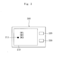
- Fig. 2 is a plane view of the pattern editing unit in the apparatus for setting a function of switches of a construction vehicle according to one embodiment of the present invention
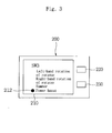
- Fig. 3 is an exemplary diagram of the pattern editing unit of FIG. 2, in which a function of switch 3 is set.
- the display screen 210 displays a screen similar to one of Fig. 2.
- the "SW1", “SW2”, and “SW3” on the screen 210 denote the switches 10a, 10b, and 20a, respectively and an item setting symbol 211 moves up and down along the character string, thereby allowing the driver to select the item he wants to change. For instance, every time the driver presses the first button 220, the item setting symbol 211 moves between the items "SW1", “SW2", and "SW3". Suppose that the driver pressed the second button 230 while the item setting symbol 211 is next to the "SW3". Then the screen of Fig. 2 tums to another screen shown in Fig. 3, displaying functions of the SW3 20a.
- FIG. 3 illustrates the functions the switch SW3 20a carries out.
- Each character string "Left-hand rotation”, “Right-hand rotation”, “Hammer”, and “Power boost” indicates functions set on the switch SW3 20a.
- the item setting symbol 212 moves between the item setting symbols 210.
- the driver presses the first button 220 to place the item selection symbol 212 at a desired item, and presses the second button 230 to change the relations between the switches 10a, 10b, and 20a and the driving units 51, 52, 53, and 54, that is, the switching pattern of the input ports DI 130 and the output ports DO 140.
- the changed relations are stored in the memory 120 of the controller 100. Later when the key (not shown) of the construction vehicle is turned on again, the CPU 110 reads out the changed relations stored in the memory 120 and matches the input ports DI 130 to the output ports DO 140 on the basis of the new relations, and outputs a signal to the output port DO 140.
- Fig. 4 is a flow chart describing how to set a function of switches by the apparatus for setting a function of switches of a construction vehicle according to one embodiment of the present invention.
- the pattern editing unit 200 is used to change the relations stored in the memory 120 and to store the changed relations in the memory 120 again.
- the method for setting a function of switches using the pattern editing unit 200 includes the steps of: selecting a switch (S200), selecting an objective function (S300), setting a function (S400), and storing a changed pattern (S500).
- the driver To operate the pattern editing unit 200, the driver first needs to operate a selection switch (not shown) of the construction vehicle. Once the pattern editing unit 200 starts operating, the screen shown in Fig. 2 is displayed and the driver can start setting a desired function of switches (S100).
- the screen shown in Fig. 2 corresponds to the switch selecting step (S200).
- the driver presses the first button 220 to place the item selection symbol 211 at one of the switches "SW1", “SW2", and “SW3”, and then presses the second button 230 to select a switch he wants to change a function thereof.
- the screen shown in Fig. 3 corresponds to the selecting an objective function step (S300).
- the driver sets an objective function to a selected switch by pressing the first button 220. That is to say, the driver needs to press the first button 220 in order to place the item selection symbol 212 at the objective function among the "Left-hand rotation”, “Right-hand rotation”, “Hammer”, and "Power boost”.
- the driver presses the second button 230 to set the objective function selected in the step 300 to the corresponding switch (S400).
- the changed relation in the function setting step (S400) is stored in the memory 120 of the controller 100 (S500). This is accomplished by turning off the key (not shown) of the construction vehicle.
- the method for setting the function of switches is complete (S600).
- the driver simply needs to turn on the key (not shown) of the construction vehicle again.
- the CPU 110 reads out the changed relations from the memory 120 and matches the input ports DI 130 to the output ports DO 140 according to the new relations, and outputs a signal to the output port DO 140.
- each switch is now ready to carry out its function according to the new pattern.
- the apparatus for setting a function of switches of a construction vehicle of the present invention enables a construction vehicle driver to freely set or arrange the switches as desired, so that the driver feels more convenient to use the switches and thus, the work efficiency can be improved.
Landscapes
- Engineering & Computer Science (AREA)
- Structural Engineering (AREA)
- Mining & Mineral Resources (AREA)
- Civil Engineering (AREA)
- General Engineering & Computer Science (AREA)
- Life Sciences & Earth Sciences (AREA)
- Hydrology & Water Resources (AREA)
- Public Health (AREA)
- Water Supply & Treatment (AREA)
- Health & Medical Sciences (AREA)
- Operation Control Of Excavators (AREA)
- Keying Circuit Devices (AREA)
- Instrument Panels (AREA)
- Component Parts Of Construction Machinery (AREA)
Applications Claiming Priority (2)
| Application Number | Priority Date | Filing Date | Title |
|---|---|---|---|
| KR2004025295 | 2004-04-13 | ||
| KR1020040025295A KR100621982B1 (ko) | 2004-04-13 | 2004-04-13 | 중장비의 기능스위치 패턴설정장치 |
Publications (2)
| Publication Number | Publication Date |
|---|---|
| EP1586712A2 true EP1586712A2 (de) | 2005-10-19 |
| EP1586712A3 EP1586712A3 (de) | 2007-01-03 |
Family
ID=34925973
Family Applications (1)
| Application Number | Title | Priority Date | Filing Date |
|---|---|---|---|
| EP04017917A Withdrawn EP1586712A3 (de) | 2004-04-13 | 2004-07-29 | Vorrichtung zur Einstellung der Funktion von Schaltern einer Baumaschine |
Country Status (5)
| Country | Link |
|---|---|
| US (1) | US7069131B2 (de) |
| EP (1) | EP1586712A3 (de) |
| JP (1) | JP2005299370A (de) |
| KR (1) | KR100621982B1 (de) |
| CN (1) | CN1683722A (de) |
Cited By (6)
| Publication number | Priority date | Publication date | Assignee | Title |
|---|---|---|---|---|
| WO2008066648A3 (en) * | 2006-11-30 | 2008-08-14 | Caterpillar Inc | Repositioning assist for an excavating operation |
| EP2028320A1 (de) * | 2007-08-20 | 2009-02-25 | JCB Compact Products Limited | Verfahren zur Steuerung einer Arbeitsmaschine |
| US7729835B2 (en) | 2007-08-21 | 2010-06-01 | Jcb Compact Products Limited | Method of controlling a working machine |
| EP3489978A4 (de) * | 2017-09-27 | 2019-05-29 | Komatsu Ltd. | Aggregationsschaltvorrichtung für nutzfahrzeug und nutzfahrzeug mit aggregationsschaltvorrichtung |
| WO2023036464A1 (en) * | 2021-09-07 | 2023-03-16 | Caterpillar Sarl | System and method implementing auxiliary device to work machine |
| EP3561185B1 (de) * | 2018-04-23 | 2024-01-24 | Fernsteuergeräte Kurt Oelsch GmbH | Handsteuergerät mit funktionsschalter |
Families Citing this family (10)
| Publication number | Priority date | Publication date | Assignee | Title |
|---|---|---|---|---|
| US8285458B2 (en) * | 2008-04-18 | 2012-10-09 | Caterpillar Inc. | Machine with automatic operating mode determination |
| US8190336B2 (en) * | 2008-07-17 | 2012-05-29 | Caterpillar Inc. | Machine with customized implement control |
| KR101882406B1 (ko) * | 2011-03-15 | 2018-07-26 | 가부시키가이샤 케이씨엠 | 휠 로더 |
| EP2567854B1 (de) * | 2011-09-12 | 2019-11-06 | Volvo Car Corporation | System zur Fahrer-Fahrzeug-Interaktion in einem Fahrzeug |
| JP6576757B2 (ja) * | 2015-09-17 | 2019-09-18 | 住友重機械工業株式会社 | ショベル |
| US10774504B2 (en) | 2018-06-22 | 2020-09-15 | Caterpillar Forest Products Inc. | Input-output control mapping with corresponding splash screen |
| EP3754119B1 (de) * | 2019-06-17 | 2023-08-09 | Kubota Corporation | Arbeitsfahrzeug mit verbesserten steuerventilsteuergeräten |
| CN110593347B (zh) * | 2019-06-28 | 2021-10-29 | 三一重机有限公司 | 半自动控制挖掘机和挖掘机操控方法 |
| CN113482087A (zh) * | 2021-07-28 | 2021-10-08 | 柳工常州机械有限公司 | 一种属具流量调节系统及挖掘机 |
| CN116201201A (zh) * | 2023-03-29 | 2023-06-02 | 湖州三一装载机有限公司 | 开关复用系统及工程机械 |
Family Cites Families (31)
| Publication number | Priority date | Publication date | Assignee | Title |
|---|---|---|---|---|
| US4288196A (en) * | 1979-06-14 | 1981-09-08 | Sutton Ii James O | Computer controlled backhoe |
| US4324525A (en) * | 1980-02-19 | 1982-04-13 | Anvil Attachments, Inc. | Loading apparatus |
| US4722044A (en) * | 1985-03-19 | 1988-01-26 | Sundstrand Corporation | Boom control system |
| DE3675534D1 (de) * | 1985-07-26 | 1990-12-13 | Komatsu Mfg Co Ltd | Regelanordnung fuer kraftschaufel. |
| JP2542192B2 (ja) * | 1986-06-11 | 1996-10-09 | セイレイ工業株式会社 | バックホ−の掘削作業部操作装置 |
| US4844685A (en) * | 1986-09-03 | 1989-07-04 | Clark Equipment Company | Electronic bucket positioning and control system |
| EP0892197A3 (de) * | 1987-02-04 | 1999-04-28 | Kabushiki Kaisha Komatsu Seisakusho | Verfahren zum automatischen Schalten von Kipp-Lastwagen, eingesetzt als Baustellenfahrzeuge |
| US4844658A (en) * | 1987-10-09 | 1989-07-04 | Henkels & Mccoy, Inc. | Apparatus for burying pipe under water |
| JPH01192921A (ja) * | 1988-01-27 | 1989-08-03 | Caterpillar Inc | 建設機械の作業機位置制御装置 |
| US5188502A (en) * | 1990-12-24 | 1993-02-23 | Caterpillar, Inc. | Linkage arrangement for a multi-purpose vehicle |
| US6738697B2 (en) * | 1995-06-07 | 2004-05-18 | Automotive Technologies International Inc. | Telematics system for vehicle diagnostics |
| GB2284734B (en) * | 1992-07-17 | 1997-01-22 | Komatsu Mfg Co Ltd | Intelligent graphic operation panel |
| JPH06213211A (ja) * | 1993-01-14 | 1994-08-02 | Hitachi Constr Mach Co Ltd | 操作レバーとアクチュエータの組合せ選択装置 |
| US5583844A (en) * | 1993-06-19 | 1996-12-10 | The Walt Disney Company | Programming device and method for controlling ride vehicles in an amusement attraction |
| KR100328218B1 (ko) * | 1996-04-30 | 2002-06-26 | 볼보 컨스트럭션 이키프먼트 홀딩 스웨덴 에이비 | 유압식건설기계의조작방식선택장치및방법 |
| US6184779B1 (en) * | 1997-01-29 | 2001-02-06 | Directed Electronics Inc. | Vehicle security system having wireless function-programming capability |
| US6209408B1 (en) * | 1997-07-16 | 2001-04-03 | Grand Haven Stamped Products | Electrical sensing system for a vehicle shifter |
| JPH1148823A (ja) * | 1997-08-04 | 1999-02-23 | Mitsubishi Motors Corp | 車両用定速走行装置 |
| JPH10152867A (ja) * | 1997-12-26 | 1998-06-09 | Komatsu Ltd | 油圧式掘削機の操作パターン変換モニタ装置 |
| US6445287B1 (en) * | 2000-02-28 | 2002-09-03 | Donnelly Corporation | Tire inflation assistance monitoring system |
| JPH11303151A (ja) * | 1998-04-17 | 1999-11-02 | Hitachi Constr Mach Co Ltd | 建設機械の表示制御装置 |
| JPH11324026A (ja) * | 1998-05-14 | 1999-11-26 | Komatsu Ltd | 建設機械における操作子とアクチュエータ組合せ変更装置および作業モード変更装置 |
| KR100656036B1 (ko) * | 1998-12-04 | 2006-12-08 | 신갸타피라 미쓰비시 가부시키가이샤 | 건설기계 |
| AU767604B2 (en) * | 1998-12-22 | 2003-11-20 | Caterpillar Inc. | Tool recognition and control system for a work machine |
| US6134494A (en) * | 1999-04-20 | 2000-10-17 | Case Corporation | Automatic power takeoff control system |
| US6173225B1 (en) * | 1999-04-20 | 2001-01-09 | Case Corporation | Power takeoff control system |
| AT4125U1 (de) * | 1999-04-28 | 2001-02-26 | Case Steyr Landmaschinentechni | Vorrichtung und verfahren zum verändern der ist-geschwindigkeit eines arbeitsfahrzeuges mit stufenlosgetriebe und tempomatfunktion |
| FR2814552B1 (fr) * | 2000-09-28 | 2003-01-24 | Renault Agriculture | Systeme et procede de commande d'outils, et engin correspondant |
| ES2329112T3 (es) * | 2000-09-28 | 2009-11-23 | Graeme K. Robertson | Sistema de suspension. |
| JP2003058285A (ja) * | 2001-08-10 | 2003-02-28 | Fujitsu Ten Ltd | 制御システム |
| US6643577B1 (en) * | 2002-08-22 | 2003-11-04 | Caterpillar Inc | Operator control station and method for a work machine having more than one function |
-
2004
- 2004-04-13 KR KR1020040025295A patent/KR100621982B1/ko not_active Expired - Fee Related
- 2004-07-14 US US10/890,741 patent/US7069131B2/en not_active Expired - Fee Related
- 2004-07-29 EP EP04017917A patent/EP1586712A3/de not_active Withdrawn
- 2004-08-24 CN CNA2004100641789A patent/CN1683722A/zh active Pending
- 2004-08-27 JP JP2004249024A patent/JP2005299370A/ja active Pending
Cited By (9)
| Publication number | Priority date | Publication date | Assignee | Title |
|---|---|---|---|---|
| WO2008066648A3 (en) * | 2006-11-30 | 2008-08-14 | Caterpillar Inc | Repositioning assist for an excavating operation |
| US7634863B2 (en) | 2006-11-30 | 2009-12-22 | Caterpillar Inc. | Repositioning assist for an excavating operation |
| EP2028320A1 (de) * | 2007-08-20 | 2009-02-25 | JCB Compact Products Limited | Verfahren zur Steuerung einer Arbeitsmaschine |
| US7729835B2 (en) | 2007-08-21 | 2010-06-01 | Jcb Compact Products Limited | Method of controlling a working machine |
| EP3489978A4 (de) * | 2017-09-27 | 2019-05-29 | Komatsu Ltd. | Aggregationsschaltvorrichtung für nutzfahrzeug und nutzfahrzeug mit aggregationsschaltvorrichtung |
| US10450724B2 (en) | 2017-09-27 | 2019-10-22 | Komatsu Ltd. | Work vehicle collective switch apparatus and work vehicle equipped with collective switch apparatus |
| EP3561185B1 (de) * | 2018-04-23 | 2024-01-24 | Fernsteuergeräte Kurt Oelsch GmbH | Handsteuergerät mit funktionsschalter |
| WO2023036464A1 (en) * | 2021-09-07 | 2023-03-16 | Caterpillar Sarl | System and method implementing auxiliary device to work machine |
| US12018455B2 (en) | 2021-09-07 | 2024-06-25 | Caterpillar Sarl | System and method implementing auxiliary device to work machine |
Also Published As
| Publication number | Publication date |
|---|---|
| EP1586712A3 (de) | 2007-01-03 |
| KR100621982B1 (ko) | 2006-09-14 |
| US7069131B2 (en) | 2006-06-27 |
| JP2005299370A (ja) | 2005-10-27 |
| CN1683722A (zh) | 2005-10-19 |
| KR20050100115A (ko) | 2005-10-18 |
| US20050228548A1 (en) | 2005-10-13 |
Similar Documents
| Publication | Publication Date | Title |
|---|---|---|
| EP1586712A2 (de) | Vorrichtung zur Einstellung der Funktion von Schaltern einer Baumaschine | |
| US7010367B2 (en) | Operator interface for a work machine | |
| US7738979B2 (en) | Work tool notification and user-selectable machine control configuration | |
| US20050203691A1 (en) | Automatic vibration device and method for use in construction equipment | |
| WO2008054624A1 (en) | Machine operator interface having linked help feature | |
| NO343307B1 (no) | Brukergrensesnitt for fjellborerigg | |
| US7102623B2 (en) | Control panel | |
| EP4190617A1 (de) | Betriebsvorrichtung, arbeitsfahrzeug und betriebssteuerungsverfahren | |
| JP3831033B2 (ja) | 油圧式建設機械の操作方式選択装置及び方法 | |
| WO1990010116A1 (fr) | Machine a direction hydraulique de type a commande electronique | |
| JP2007332563A (ja) | 建設機械の操作系制御装置 | |
| CN101727273A (zh) | 车用操作和显示装置 | |
| KR20050037624A (ko) | 자리수 키를 이용한 영상/음성 제어장치 및 그 제어방법 | |
| JP2008114814A (ja) | 建設機械のビデオカメラ切替装置 | |
| JP4741214B2 (ja) | 運転パラメータ設定装置 | |
| US9565739B2 (en) | Lamp control device of construction machine and lamp control method therefor | |
| JPH0876978A (ja) | Lcdタッチスクリーンを用いたリモート・コントローラ及びリモート・コントロール方法 | |
| KR20100074879A (ko) | 자동차용 다기능 모니터 스위치 | |
| JP4458006B2 (ja) | デジタルミキサ | |
| WO2017110520A1 (ja) | 表示装置 | |
| KR20040106162A (ko) | 자동차의 기능 선택 장치 | |
| CN105934403A (zh) | 使用gui的支腿和推土机控制 | |
| JP2001356805A (ja) | 操作装置 | |
| JPH08277550A (ja) | 制御パネル | |
| CN109025956B (zh) | 工程机械控制组件、工程机械及面板功能切换控制方法 |
Legal Events
| Date | Code | Title | Description |
|---|---|---|---|
| PUAI | Public reference made under article 153(3) epc to a published international application that has entered the european phase |
Free format text: ORIGINAL CODE: 0009012 |
|
| 17P | Request for examination filed |
Effective date: 20040729 |
|
| AK | Designated contracting states |
Kind code of ref document: A2 Designated state(s): AT BE BG CH CY CZ DE DK EE ES FI FR GB GR HU IE IT LI LU MC NL PL PT RO SE SI SK TR |
|
| AX | Request for extension of the european patent |
Extension state: AL HR LT LV MK |
|
| PUAL | Search report despatched |
Free format text: ORIGINAL CODE: 0009013 |
|
| AK | Designated contracting states |
Kind code of ref document: A3 Designated state(s): AT BE BG CH CY CZ DE DK EE ES FI FR GB GR HU IE IT LI LU MC NL PL PT RO SE SI SK TR |
|
| AX | Request for extension of the european patent |
Extension state: AL HR LT LV MK |
|
| AKX | Designation fees paid |
Designated state(s): DE FR GB IT |
|
| 17Q | First examination report despatched |
Effective date: 20071123 |
|
| STAA | Information on the status of an ep patent application or granted ep patent |
Free format text: STATUS: THE APPLICATION HAS BEEN WITHDRAWN |
|
| 18W | Application withdrawn |
Effective date: 20071221 |