EP1586713B1 - Dispositif et méthode d'initiation automatique de rincage d'un dispositif de chasse d'eau utilisant un capteur capacitif - Google Patents
Dispositif et méthode d'initiation automatique de rincage d'un dispositif de chasse d'eau utilisant un capteur capacitif Download PDFInfo
- Publication number
- EP1586713B1 EP1586713B1 EP04405231A EP04405231A EP1586713B1 EP 1586713 B1 EP1586713 B1 EP 1586713B1 EP 04405231 A EP04405231 A EP 04405231A EP 04405231 A EP04405231 A EP 04405231A EP 1586713 B1 EP1586713 B1 EP 1586713B1
- Authority
- EP
- European Patent Office
- Prior art keywords
- siphon
- flushing
- sealing water
- overflow edge
- electrode
- Prior art date
- Legal status (The legal status is an assumption and is not a legal conclusion. Google has not performed a legal analysis and makes no representation as to the accuracy of the status listed.)
- Expired - Lifetime
Links
- 238000011010 flushing procedure Methods 0.000 title claims abstract description 29
- 238000000034 method Methods 0.000 title claims abstract description 9
- XLYOFNOQVPJJNP-UHFFFAOYSA-N water Substances O XLYOFNOQVPJJNP-UHFFFAOYSA-N 0.000 claims abstract description 29
- 238000007789 sealing Methods 0.000 claims abstract description 19
- 230000001960 triggered effect Effects 0.000 claims description 9
- 230000007774 longterm Effects 0.000 claims description 8
- 238000005259 measurement Methods 0.000 claims description 8
- 238000011156 evaluation Methods 0.000 claims description 3
- 238000011144 upstream manufacturing Methods 0.000 claims 2
- 230000029142 excretion Effects 0.000 claims 1
- 239000003990 capacitor Substances 0.000 abstract description 4
- 230000002452 interceptive effect Effects 0.000 abstract 1
- 238000010926 purge Methods 0.000 description 4
- 239000000523 sample Substances 0.000 description 4
- 230000007423 decrease Effects 0.000 description 3
- 230000001419 dependent effect Effects 0.000 description 2
- 238000010586 diagram Methods 0.000 description 2
- 239000002352 surface water Substances 0.000 description 2
- 238000009736 wetting Methods 0.000 description 2
- 235000008733 Citrus aurantifolia Nutrition 0.000 description 1
- 235000011941 Tilia x europaea Nutrition 0.000 description 1
- 230000002308 calcification Effects 0.000 description 1
- 238000004364 calculation method Methods 0.000 description 1
- 238000011109 contamination Methods 0.000 description 1
- 238000005260 corrosion Methods 0.000 description 1
- 230000007797 corrosion Effects 0.000 description 1
- 230000003247 decreasing effect Effects 0.000 description 1
- 230000003111 delayed effect Effects 0.000 description 1
- 230000000694 effects Effects 0.000 description 1
- 230000002209 hydrophobic effect Effects 0.000 description 1
- 230000002262 irrigation Effects 0.000 description 1
- 238000003973 irrigation Methods 0.000 description 1
- 239000004571 lime Substances 0.000 description 1
- 239000007788 liquid Substances 0.000 description 1
- 230000002035 prolonged effect Effects 0.000 description 1
- 239000005871 repellent Substances 0.000 description 1
Images


Classifications
-
- G—PHYSICS
- G01—MEASURING; TESTING
- G01F—MEASURING VOLUME, VOLUME FLOW, MASS FLOW OR LIQUID LEVEL; METERING BY VOLUME
- G01F23/00—Indicating or measuring liquid level or level of fluent solid material, e.g. indicating in terms of volume or indicating by means of an alarm
- G01F23/22—Indicating or measuring liquid level or level of fluent solid material, e.g. indicating in terms of volume or indicating by means of an alarm by measuring physical variables, other than linear dimensions, pressure or weight, dependent on the level to be measured, e.g. by difference of heat transfer of steam or water
- G01F23/26—Indicating or measuring liquid level or level of fluent solid material, e.g. indicating in terms of volume or indicating by means of an alarm by measuring physical variables, other than linear dimensions, pressure or weight, dependent on the level to be measured, e.g. by difference of heat transfer of steam or water by measuring variations of capacity or inductance of capacitors or inductors arising from the presence of liquid or fluent solid material in the electric or electromagnetic fields
- G01F23/263—Indicating or measuring liquid level or level of fluent solid material, e.g. indicating in terms of volume or indicating by means of an alarm by measuring physical variables, other than linear dimensions, pressure or weight, dependent on the level to be measured, e.g. by difference of heat transfer of steam or water by measuring variations of capacity or inductance of capacitors or inductors arising from the presence of liquid or fluent solid material in the electric or electromagnetic fields by measuring variations in capacitance of capacitors
- G01F23/265—Indicating or measuring liquid level or level of fluent solid material, e.g. indicating in terms of volume or indicating by means of an alarm by measuring physical variables, other than linear dimensions, pressure or weight, dependent on the level to be measured, e.g. by difference of heat transfer of steam or water by measuring variations of capacity or inductance of capacitors or inductors arising from the presence of liquid or fluent solid material in the electric or electromagnetic fields by measuring variations in capacitance of capacitors for discrete levels
-
- E—FIXED CONSTRUCTIONS
- E03—WATER SUPPLY; SEWERAGE
- E03D—WATER-CLOSETS OR URINALS WITH FLUSHING DEVICES; FLUSHING VALVES THEREFOR
- E03D5/00—Special constructions of flushing devices, e.g. closed flushing system
- E03D5/10—Special constructions of flushing devices, e.g. closed flushing system operated electrically, e.g. by a photo-cell; also combined with devices for opening or closing shutters in the bowl outlet and/or with devices for raising/or lowering seat and cover and/or for swiveling the bowl
- E03D5/105—Special constructions of flushing devices, e.g. closed flushing system operated electrically, e.g. by a photo-cell; also combined with devices for opening or closing shutters in the bowl outlet and/or with devices for raising/or lowering seat and cover and/or for swiveling the bowl touchless, e.g. using sensors
Definitions
- the invention relates to a device for automatically flushing a flushing device according to the preamble of claim 1.
- the US Pat. No. 669,037 A discloses a urinal with an automatic flush.
- a float is arranged, which closes a circuit with increasing level of the water present in the siphon and thus causes a flush.
- the rinse water pivots a lever that closes the circuit. So that the float is raised, a threshold is required at the outlet of the siphon.
- the WO 02/50498 A discloses a method and apparatus for measuring water levels. On a cistern outside a capacitive sensor is arranged. Due to the level measurement, the inlet valve and the outlet valve can be controlled. An automatic rinse triggering is not possible and not intended.
- the DE 101 11 210 A discloses a method for controlling the irrigation of a urinal.
- the flushing is carried out by a conductivity measurement with three electrodes.
- the DE 32 28 061 A a device for flushing a toilet system, in which electrodes are arranged in the region of the siphon after the overflow edge.
- the electrodes are capacitive electrodes and cause a purge via a controller as soon as the dielectric of the capacitor changes in the siphon due to contamination.
- the rinsing process is triggered at a certain, adjustable threshold and terminated after a preselectable delay time.
- the electrodes are attached to the outer surface of the siphon, whereby corrosion of the electrodes should be avoided.
- a device with two arranged in the interior of the siphon electrodes is from the CH 491 257 known.
- the DE 199 50 874 A discloses a urinal flushing device in which a probe is provided which is arranged in a protruding region of the urinal.
- the probe is designed as a proximity sensor and has an evaluation electronics whose output signal is dependent on the capacitance of the probe. An output signal controls a solenoid valve.
- a probe is arranged at the drainage pipe of the odor trap, which fulfills the function of a flow monitor. In the case of a blockage, the flushing operation is interrupted.
- a device for triggering a flushing process which has at least one electrode which is arranged below the overflow point of the siphon. If an overflow occurs over the overflow edge of the siphon, the inside surface of the siphon is wetted, causing a change in capacity. The electrode or the sensor thus responds to a wetting of the inner surface of the siphon.
- the invention has for its object to provide a device and a method of the type mentioned, which ensures greater reliability, but can still be realized comparatively inexpensive.
- the invention is achieved in a generic device according to claim 1.
- it is not a change in capacity due to wetting of the inner surface of the siphon that is detected, but the change in capacity due to a change in the water level in the siphon and, accordingly, a purge is triggered.
- the dielectric of the capacitor is essentially formed by the sealing water and deposits. The proportion of surface water and deposits is comparatively small.
- the invention also allows a measurement of the level height. If, for example, a siphon is not filled to the overflow edge, then such an incomplete filling can be detected via the sensor and a final rinse can be triggered.
- the capacitive sensor measures in the area of the sealing water and in the air area immediately above the level of the sealing water. The measured capacity is to a certain extent a mixed calculation between the capacity of the sealing water and the overlying airspace. Calcification on the inside after the overflow edge can affect the measurement less.
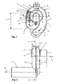
- the figures show a device 1, which in particular has a urinal siphon with a housing 2, which consists of two interconnected housing halves 21 and 22.
- a siphon inlet 6 is provided, in the direction of the arrow 9, the liquid to be discharged flows.
- sealing water S forms an odor trap in front of an overflow edge 8. flows from a urinal basin, not shown here, water through the siphon inlet 6 into the housing 2, so rises in FIG. 1 shown surface 15 of the sealing water S and flows under a siphon effect in the directions of the arrows 12 and 13 to a siphon outlet 7 and leaves it accordingly FIG. 2 in the direction of the arrow 10 and finally flows into a disposal line, not shown here.
- By flushing the sealing water S is refilled to the overflow edge 8 again. This flows through the siphon inlet 6 into the housing 2 and in the direction of the arrow 12 around an edge 20.
- a sensor 3 For the automatic triggering of a flushing, a sensor 3 is provided according to FIG. 4 an electronic unit 5 which activates a rinsing device 4 for rinsing release.
- the flushing device 4 is for example a cistern with a solenoid valve which is opened and closed by signals. It is also conceivable flushing via another flushing device, such as a flush valve with a corresponding controllable valve.
- the sensor 3 has two electrodes 14 and 16, which according to the Figures 2 and 4 are arranged on an outer side 25 of the housing 2. These electrodes 14 and 16 are arranged at a distance from each other and are seen in the flow direction in front of the overflow edge 8, wherein each part of the electrode in the region of the sealing water S and part of the electrode in the region of an air space L is above the level 15. For the electrode 14, these two areas are in FIG. 1 labeled 14a and 14b.
- the dielectric of the sensor 3 is partially by sealing water S and partly formed by the airspace L. The measured capacity is thus determined by the sealing water S and by the air space L. If the urinal is used, the surface 15 rises and accordingly the influence of the air space L on the capacity decreases. If the surface 15 drops, the capacity in the other direction changes accordingly.
- the measured capacity is an indicator of the in FIG. 1 drawn level height H. With increasing surface 15, the capacity increases and with decreasing surface 15 decreases accordingly the capacity.
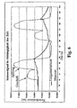
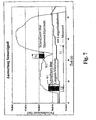
- the capacity is continuously measured by the sensor 3. From the measurements is in the FIGS. 6 and 7 determined long-term average. If the long-term average is exceeded by a predetermined threshold value for a predetermined period, the store is recognized. A purge is triggered as soon as a maximum value falls below a threshold value for a given duration. During rinsing the capacity increases sharply, but then decreases by the emptying and falls below the long-term average. By refilling with blocked water S, the capacity returns to its original value.
- the FIG. 5 shows the course of the field lines 18 and 19 between the electrodes 14 and 16, which are formed as measuring electrodes.
- the field lines 19 extend through lateral walls of the housing 2 and are influenced by deposits and surface water and therefore do not run in a straight line, as is almost the case with the field lines 18.
- With a known guard electrode 17 field lines 19 and any interference fields are largely hidden and therefore not taken into account in the measurement. Therefore, the reliability can be increased even with a long service life even further. The measurement is thus largely based on the undisturbed field.
- FIG. 6 The course of a sensor signal in two subsequent uses of the inventive device 1 is in FIG. 6 shown.
- the measured value increases slightly during use and a corresponding increase in the surface 15 and then drops again, but then rises again sharply to a still higher value after a flushing action.
- flushing the siphon is briefly completely filled with rinse water and correspondingly high capacity. After the water has been sucked off, the fill level drops and then rises again when the bowl is rinsed.
- the course of the long-term average changes accordingly, as the FIG. 6 shows.
- a business is recognized as such when the in FIG. 7 shown threshold value W1 is exceeded over the long-term average for a period of time T1. If the long-term mean is exceeded by a threshold value for a given duration, the store is recognized. If the maximum value falls below a threshold value for a given duration, the flushing is triggered. After flushing a shop, flushing is not triggered until a maximum value has fallen below a threshold value W2 during a predetermined and adjustable period of time T2, or a predetermined time period T3 has elapsed. The triggering of the flushing is thus delayed, for which purpose a corresponding algorithm is provided. If incomplete flushing and therefore the intended level height H is not reached, this is detected by the electronics, since the capacity remains correspondingly small. About the electronics 14 then a final rinse is triggered, which fills the siphon housing 2 accordingly.
Landscapes
- Engineering & Computer Science (AREA)
- Physics & Mathematics (AREA)
- Power Engineering (AREA)
- Water Supply & Treatment (AREA)
- Hydrology & Water Resources (AREA)
- Public Health (AREA)
- Life Sciences & Earth Sciences (AREA)
- Health & Medical Sciences (AREA)
- Aviation & Aerospace Engineering (AREA)
- Electromagnetism (AREA)
- Thermal Sciences (AREA)
- Fluid Mechanics (AREA)
- General Physics & Mathematics (AREA)
- Investigating Or Analyzing Materials By The Use Of Electric Means (AREA)
- Cleaning By Liquid Or Steam (AREA)
Claims (7)
- Dispositif d'initiation automatique de rinçage d'un dispositif de chasse d'eau (4), comprenant un siphon (2), qui présente une entrée (6) et une sortie (7) ainsi qu'un bord de débordement (8) et un canal montant vers le bord de débordement (8), avec des moyens (14, 16) pour détecter une augmentation de la surface (15) de l'eau de blocage (S) dans le siphon (2), caractérisé en ce que du côté extérieur (25) du siphon (2) est disposé un capteur capacitif (3) qui présente au moins une électrode (14, 16), qui est disposée, vu dans la direction d'écoulement, avant le bord de débordement (8) dans la région de la surface (15) de l'eau de blocage (S), ladite surface (15) se trouvant dans le canal montant vers le bord de débordement (8).
- Dispositif selon la revendication 1, caractérisé en ce que l'on détecte des variations de la hauteur de niveau de remplissage (H).
- Dispositif selon la revendication 1 ou 2, caractérisé en ce que le capteur (3) présente au moins une protection (17) pour dévier les champs parasites.
- Dispositif selon l'une quelconque des revendications 1 à 3, caractérisé en ce que l'au moins une électrode (14, 16) présente une partie (14a) qui est disposée au-dessus de la surface (15) de l'eau de blocage (S) et en ce qu'une autre partie (14b) de l'au moins une électrode (14, 16) se trouve dans la région de l'eau de blocage (S).
- Dispositif selon l'une quelconque des revendications 1 à 4, caractérisé en ce que l'au moins une électrode (14, 16) est disposée du côté extérieur (25) d'un boîtier de siphon (2).
- Procédé d'initiation automatique de rinçage d'un dispositif de chasse d'eau, comprenant un siphon (2) avec un canal montant vers un bord de débordement (8) et avec des moyens (14, 16) pour détecter une montée de la surface (15) de l'eau de blocage (S) dans le siphon, la montée étant analysée en vue d'une initiation de rinçage, caractérisé en ce que l'on prévoit un capteur capacitif (3) sur le côté extérieur (25) du siphon (2) ainsi qu'une électronique d'analyse (16), et en ce que des variations de la constante diélectrique dans la région de la surface (15) de l'eau de blocage (S) dans la direction d'écoulement depuis le bord de débordement (8) sont détectées, ladite surface (15) se trouvant dans le canal montant vers le bord de débordement (8).
- Procédé selon la revendication 6, caractérisé en ce que la capacité du capteur (3) est mesurée en continu et l'on détecte à partir des mesures une valeur moyenne de durée, en ce que l'on détecte si quelqu'un a fait ses besoins si, pendant une durée prédéterminée, la moyenne de durée est dépassée d'une valeur seuil prédéterminée, et en ce qu'un rinçage est initié dès que pendant une durée prédéterminée, une valeur maximale n'est pas atteinte.
Priority Applications (3)
| Application Number | Priority Date | Filing Date | Title |
|---|---|---|---|
| AT04405231T ATE451506T1 (de) | 2004-04-15 | 2004-04-15 | Vorrichtung und verfahren zur selbstständigen spülauslösung einer spülvorrichtung mittels eines kapazitiven sensors |
| DE502004010488T DE502004010488D1 (de) | 2004-04-15 | 2004-04-15 | Vorrichtung und Verfahren zur selbstständigen Spülauslösung einer Spülvorrichtung mittels eines kapazitiven Sensors |
| EP04405231A EP1586713B1 (fr) | 2004-04-15 | 2004-04-15 | Dispositif et méthode d'initiation automatique de rincage d'un dispositif de chasse d'eau utilisant un capteur capacitif |
Applications Claiming Priority (1)
| Application Number | Priority Date | Filing Date | Title |
|---|---|---|---|
| EP04405231A EP1586713B1 (fr) | 2004-04-15 | 2004-04-15 | Dispositif et méthode d'initiation automatique de rincage d'un dispositif de chasse d'eau utilisant un capteur capacitif |
Publications (2)
| Publication Number | Publication Date |
|---|---|
| EP1586713A1 EP1586713A1 (fr) | 2005-10-19 |
| EP1586713B1 true EP1586713B1 (fr) | 2009-12-09 |
Family
ID=34932058
Family Applications (1)
| Application Number | Title | Priority Date | Filing Date |
|---|---|---|---|
| EP04405231A Expired - Lifetime EP1586713B1 (fr) | 2004-04-15 | 2004-04-15 | Dispositif et méthode d'initiation automatique de rincage d'un dispositif de chasse d'eau utilisant un capteur capacitif |
Country Status (3)
| Country | Link |
|---|---|
| EP (1) | EP1586713B1 (fr) |
| AT (1) | ATE451506T1 (fr) |
| DE (1) | DE502004010488D1 (fr) |
Cited By (1)
| Publication number | Priority date | Publication date | Assignee | Title |
|---|---|---|---|---|
| US9328490B2 (en) | 2006-10-24 | 2016-05-03 | Bradley Fixtures Corporation | Capacitive sensing for washroom fixture |
Families Citing this family (5)
| Publication number | Priority date | Publication date | Assignee | Title |
|---|---|---|---|---|
| ATE453765T1 (de) * | 2006-08-07 | 2010-01-15 | Kotte Gmbh & Co Kg | Verfahren und vorrichtung zur erfassung der nutzung von urinalen und zur auslösung einer automatischen spülung |
| CN101230592B (zh) * | 2007-12-27 | 2011-04-27 | 上海科勒电子科技有限公司 | 自动感应小便斗 |
| DE202010002565U1 (de) * | 2010-02-19 | 2010-05-27 | Sanitärtechnik Eisenberg GmbH | Absaugsiphon |
| EP3521524A1 (fr) * | 2018-02-06 | 2019-08-07 | IPee N.V. | Appareil sanitaire comprenant un circuit de capteur et son utilisation |
| DE102019125370A1 (de) | 2019-09-20 | 2021-03-25 | Caroma Industries Limited | Urinalsystem, Wasserverbrauchersystem mit einem Urinalsystem und Verfahren zum Betreiben eines Urinalsystems |
Family Cites Families (5)
| Publication number | Priority date | Publication date | Assignee | Title |
|---|---|---|---|---|
| US669037A (en) * | 1898-11-03 | 1901-02-26 | John Walter Stevens | Automatic flushing-tank. |
| DE3228061A1 (de) * | 1981-07-28 | 1983-02-17 | Bieri Pumpenbau AG, 3110 Münsingen, Bern | Vorrichtung zum betaetigen der spuelung einer wc-anlage |
| DE10006670A1 (de) * | 1999-12-22 | 2001-07-05 | Friatec Ag | Vorrichtung zum Auslösen eines Spülvorgangs eines Urinals oder WC |
| WO2002050498A1 (fr) * | 2000-12-20 | 2002-06-27 | Abertax Research And Development Ltd. | Procede et dispositif de mesure de niveaux |
| DE10111210B4 (de) * | 2001-03-08 | 2005-05-12 | Mepa-Pauli Und Menden Gmbh | Verfahren zur Steuerung der Spülung eines Urinals |
-
2004
- 2004-04-15 EP EP04405231A patent/EP1586713B1/fr not_active Expired - Lifetime
- 2004-04-15 DE DE502004010488T patent/DE502004010488D1/de not_active Expired - Lifetime
- 2004-04-15 AT AT04405231T patent/ATE451506T1/de active
Cited By (1)
| Publication number | Priority date | Publication date | Assignee | Title |
|---|---|---|---|---|
| US9328490B2 (en) | 2006-10-24 | 2016-05-03 | Bradley Fixtures Corporation | Capacitive sensing for washroom fixture |
Also Published As
| Publication number | Publication date |
|---|---|
| ATE451506T1 (de) | 2009-12-15 |
| DE502004010488D1 (de) | 2010-01-21 |
| EP1586713A1 (fr) | 2005-10-19 |
Similar Documents
| Publication | Publication Date | Title |
|---|---|---|
| EP3335611B1 (fr) | Machine de nettoyage de sol avec mesure de niveau de remplissage du réservoir d'eau sale | |
| DE68910600T2 (de) | Wasserklosettspülvorrichtung. | |
| EP3418457A1 (fr) | Système de surveillance permettant de surveiller un niveau d'eau dans un élément sanitaire ainsi qu'un élément sanitaire | |
| CH663045A5 (de) | Ablaufgarnitur fuer einen spuelkasten. | |
| EP1586713B1 (fr) | Dispositif et méthode d'initiation automatique de rincage d'un dispositif de chasse d'eau utilisant un capteur capacitif | |
| DE102011011624A1 (de) | Wasserversorgungseinrichtung für einen Sanitärgegenstand | |
| AT4952U1 (de) | Spülkasten für eine klosettanlage sowie verfahren zur betätigung eines solchen spülkastens | |
| DE2745498A1 (de) | Vorrichtung zur steuerung einer fluessigkeitsbeigabe | |
| DE8908051U1 (de) | Radarsonde zur selbsttätigen Einzelsteuerung von Sanitärarmaturen | |
| DE4202245A1 (de) | Vorrichtung zum abzweigen von regenwasser aus einem dachrinnenfallrohr | |
| DE102004006973A1 (de) | Dampfgargerät | |
| DE60124980T2 (de) | Vorrichtung zum Spülen eines Toilettenbeckens oder dergleichen | |
| EP3266358A1 (fr) | Lave-vaisselle comportant un bloc détecteur destiné à déterminer un mouvement rotatif d'un bras de pulvérisation | |
| DE29918335U1 (de) | Vorrichtung für die selbsttätige Auslösung eines Spülvorganges | |
| DE102005018879A1 (de) | Geschirrspüler | |
| EP2076635B1 (fr) | Procédé et dispositif pour détecter l'utilisation d'urinoirs et déclencher un rinçage automatique | |
| DE202021102529U1 (de) | Toilettenspülmodul und Toilette | |
| DE102020108234A1 (de) | Sanitäreinrichtung | |
| DE102004029567B4 (de) | Schmutzfangzelle | |
| EP4095324B1 (fr) | Système de rinçage | |
| WO2024207033A1 (fr) | Dispositif d'analyse d'urine et toilettes de séparation comportant un tel dispositif | |
| DE102019133021A1 (de) | Vorrichtung zum Spülen eines sanitären Beckens und System zur Wasserversorgung eines Sanitärgegenstandes mit einer solchen Vorrichtung | |
| DE102011013696A1 (de) | Ablaufvorrichtung für einen Feuchtraum | |
| EP3705457A1 (fr) | Installation de nettoyage, en particulier pour eaux usées, permettant de séparer un liquide léger et/ou des graisses et procédé de fonctionnement d'une installation de nettoyage | |
| DE202007015077U1 (de) | Siphon für sanitäre Spülsysteme, insbesondere für Urinale |
Legal Events
| Date | Code | Title | Description |
|---|---|---|---|
| PUAI | Public reference made under article 153(3) epc to a published international application that has entered the european phase |
Free format text: ORIGINAL CODE: 0009012 |
|
| AK | Designated contracting states |
Kind code of ref document: A1 Designated state(s): AT BE BG CH CY CZ DE DK EE ES FI FR GB GR HU IE IT LI LU MC NL PL PT RO SE SI SK TR |
|
| AX | Request for extension of the european patent |
Extension state: AL HR LT LV MK |
|
| 17P | Request for examination filed |
Effective date: 20060304 |
|
| AKX | Designation fees paid |
Designated state(s): AT BE BG CH CY CZ DE DK EE ES FI FR GB GR HU IE IT LI LU MC NL PL PT RO SE SI SK TR |
|
| 17Q | First examination report despatched |
Effective date: 20060606 |
|
| APBN | Date of receipt of notice of appeal recorded |
Free format text: ORIGINAL CODE: EPIDOSNNOA2E |
|
| APBR | Date of receipt of statement of grounds of appeal recorded |
Free format text: ORIGINAL CODE: EPIDOSNNOA3E |
|
| APAF | Appeal reference modified |
Free format text: ORIGINAL CODE: EPIDOSCREFNE |
|
| APAI | Date of receipt of notice of appeal modified |
Free format text: ORIGINAL CODE: EPIDOSCNOA2E |
|
| APAK | Date of receipt of statement of grounds of an appeal modified |
Free format text: ORIGINAL CODE: EPIDOSCNOA3E |
|
| APBT | Appeal procedure closed |
Free format text: ORIGINAL CODE: EPIDOSNNOA9E |
|
| GRAP | Despatch of communication of intention to grant a patent |
Free format text: ORIGINAL CODE: EPIDOSNIGR1 |
|
| GRAS | Grant fee paid |
Free format text: ORIGINAL CODE: EPIDOSNIGR3 |
|
| GRAA | (expected) grant |
Free format text: ORIGINAL CODE: 0009210 |
|
| RAP1 | Party data changed (applicant data changed or rights of an application transferred) |
Owner name: GEBERIT INTERNATIONAL AG |
|
| AK | Designated contracting states |
Kind code of ref document: B1 Designated state(s): AT BE BG CH CY CZ DE DK EE ES FI FR GB GR HU IE IT LI LU MC NL PL PT RO SE SI SK TR |
|
| REG | Reference to a national code |
Ref country code: GB Ref legal event code: FG4D Free format text: NOT ENGLISH |
|
| REG | Reference to a national code |
Ref country code: CH Ref legal event code: EP Ref country code: CH Ref legal event code: NV Representative=s name: ISLER & PEDRAZZINI AG |
|
| REG | Reference to a national code |
Ref country code: IE Ref legal event code: FG4D |
|
| REF | Corresponds to: |
Ref document number: 502004010488 Country of ref document: DE Date of ref document: 20100121 Kind code of ref document: P |
|
| REG | Reference to a national code |
Ref country code: NL Ref legal event code: VDEP Effective date: 20091209 |
|
| PG25 | Lapsed in a contracting state [announced via postgrant information from national office to epo] |
Ref country code: FI Free format text: LAPSE BECAUSE OF FAILURE TO SUBMIT A TRANSLATION OF THE DESCRIPTION OR TO PAY THE FEE WITHIN THE PRESCRIBED TIME-LIMIT Effective date: 20091209 Ref country code: SE Free format text: LAPSE BECAUSE OF FAILURE TO SUBMIT A TRANSLATION OF THE DESCRIPTION OR TO PAY THE FEE WITHIN THE PRESCRIBED TIME-LIMIT Effective date: 20091209 |
|
| PG25 | Lapsed in a contracting state [announced via postgrant information from national office to epo] |
Ref country code: PL Free format text: LAPSE BECAUSE OF FAILURE TO SUBMIT A TRANSLATION OF THE DESCRIPTION OR TO PAY THE FEE WITHIN THE PRESCRIBED TIME-LIMIT Effective date: 20091209 Ref country code: SI Free format text: LAPSE BECAUSE OF FAILURE TO SUBMIT A TRANSLATION OF THE DESCRIPTION OR TO PAY THE FEE WITHIN THE PRESCRIBED TIME-LIMIT Effective date: 20091209 |
|
| REG | Reference to a national code |
Ref country code: IE Ref legal event code: FD4D |
|
| PG25 | Lapsed in a contracting state [announced via postgrant information from national office to epo] |
Ref country code: PT Free format text: LAPSE BECAUSE OF FAILURE TO SUBMIT A TRANSLATION OF THE DESCRIPTION OR TO PAY THE FEE WITHIN THE PRESCRIBED TIME-LIMIT Effective date: 20100409 Ref country code: RO Free format text: LAPSE BECAUSE OF FAILURE TO SUBMIT A TRANSLATION OF THE DESCRIPTION OR TO PAY THE FEE WITHIN THE PRESCRIBED TIME-LIMIT Effective date: 20091209 Ref country code: NL Free format text: LAPSE BECAUSE OF FAILURE TO SUBMIT A TRANSLATION OF THE DESCRIPTION OR TO PAY THE FEE WITHIN THE PRESCRIBED TIME-LIMIT Effective date: 20091209 Ref country code: BG Free format text: LAPSE BECAUSE OF FAILURE TO SUBMIT A TRANSLATION OF THE DESCRIPTION OR TO PAY THE FEE WITHIN THE PRESCRIBED TIME-LIMIT Effective date: 20100309 Ref country code: EE Free format text: LAPSE BECAUSE OF FAILURE TO SUBMIT A TRANSLATION OF THE DESCRIPTION OR TO PAY THE FEE WITHIN THE PRESCRIBED TIME-LIMIT Effective date: 20091209 Ref country code: ES Free format text: LAPSE BECAUSE OF FAILURE TO SUBMIT A TRANSLATION OF THE DESCRIPTION OR TO PAY THE FEE WITHIN THE PRESCRIBED TIME-LIMIT Effective date: 20100320 Ref country code: IE Free format text: LAPSE BECAUSE OF FAILURE TO SUBMIT A TRANSLATION OF THE DESCRIPTION OR TO PAY THE FEE WITHIN THE PRESCRIBED TIME-LIMIT Effective date: 20091209 |
|
| PG25 | Lapsed in a contracting state [announced via postgrant information from national office to epo] |
Ref country code: CZ Free format text: LAPSE BECAUSE OF FAILURE TO SUBMIT A TRANSLATION OF THE DESCRIPTION OR TO PAY THE FEE WITHIN THE PRESCRIBED TIME-LIMIT Effective date: 20091209 Ref country code: SK Free format text: LAPSE BECAUSE OF FAILURE TO SUBMIT A TRANSLATION OF THE DESCRIPTION OR TO PAY THE FEE WITHIN THE PRESCRIBED TIME-LIMIT Effective date: 20091209 |
|
| PLBE | No opposition filed within time limit |
Free format text: ORIGINAL CODE: 0009261 |
|
| STAA | Information on the status of an ep patent application or granted ep patent |
Free format text: STATUS: NO OPPOSITION FILED WITHIN TIME LIMIT |
|
| PG25 | Lapsed in a contracting state [announced via postgrant information from national office to epo] |
Ref country code: GR Free format text: LAPSE BECAUSE OF FAILURE TO SUBMIT A TRANSLATION OF THE DESCRIPTION OR TO PAY THE FEE WITHIN THE PRESCRIBED TIME-LIMIT Effective date: 20100310 Ref country code: CY Free format text: LAPSE BECAUSE OF FAILURE TO SUBMIT A TRANSLATION OF THE DESCRIPTION OR TO PAY THE FEE WITHIN THE PRESCRIBED TIME-LIMIT Effective date: 20091209 |
|
| BERE | Be: lapsed |
Owner name: GEBERIT INTERNATIONAL A.G. Effective date: 20100430 |
|
| 26N | No opposition filed |
Effective date: 20100910 |
|
| PG25 | Lapsed in a contracting state [announced via postgrant information from national office to epo] |
Ref country code: MC Free format text: LAPSE BECAUSE OF NON-PAYMENT OF DUE FEES Effective date: 20100430 |
|
| GBPC | Gb: european patent ceased through non-payment of renewal fee |
Effective date: 20100415 |
|
| REG | Reference to a national code |
Ref country code: FR Ref legal event code: ST Effective date: 20101230 |
|
| PG25 | Lapsed in a contracting state [announced via postgrant information from national office to epo] |
Ref country code: DK Free format text: LAPSE BECAUSE OF FAILURE TO SUBMIT A TRANSLATION OF THE DESCRIPTION OR TO PAY THE FEE WITHIN THE PRESCRIBED TIME-LIMIT Effective date: 20091209 |
|
| PG25 | Lapsed in a contracting state [announced via postgrant information from national office to epo] |
Ref country code: BE Free format text: LAPSE BECAUSE OF NON-PAYMENT OF DUE FEES Effective date: 20100430 Ref country code: GB Free format text: LAPSE BECAUSE OF NON-PAYMENT OF DUE FEES Effective date: 20100415 Ref country code: IT Free format text: LAPSE BECAUSE OF FAILURE TO SUBMIT A TRANSLATION OF THE DESCRIPTION OR TO PAY THE FEE WITHIN THE PRESCRIBED TIME-LIMIT Effective date: 20091209 |
|
| PG25 | Lapsed in a contracting state [announced via postgrant information from national office to epo] |
Ref country code: FR Free format text: LAPSE BECAUSE OF NON-PAYMENT OF DUE FEES Effective date: 20100430 |
|
| PGFP | Annual fee paid to national office [announced via postgrant information from national office to epo] |
Ref country code: CH Payment date: 20120419 Year of fee payment: 9 |
|
| PG25 | Lapsed in a contracting state [announced via postgrant information from national office to epo] |
Ref country code: LU Free format text: LAPSE BECAUSE OF NON-PAYMENT OF DUE FEES Effective date: 20100415 Ref country code: HU Free format text: LAPSE BECAUSE OF FAILURE TO SUBMIT A TRANSLATION OF THE DESCRIPTION OR TO PAY THE FEE WITHIN THE PRESCRIBED TIME-LIMIT Effective date: 20100610 |
|
| PG25 | Lapsed in a contracting state [announced via postgrant information from national office to epo] |
Ref country code: TR Free format text: LAPSE BECAUSE OF FAILURE TO SUBMIT A TRANSLATION OF THE DESCRIPTION OR TO PAY THE FEE WITHIN THE PRESCRIBED TIME-LIMIT Effective date: 20091209 |
|
| PGFP | Annual fee paid to national office [announced via postgrant information from national office to epo] |
Ref country code: AT Payment date: 20120411 Year of fee payment: 9 |
|
| REG | Reference to a national code |
Ref country code: DE Ref legal event code: R082 Ref document number: 502004010488 Country of ref document: DE Representative=s name: HOEGER, STELLRECHT & PARTNER PATENTANWAELTE, DE Ref country code: DE Ref legal event code: R082 Ref document number: 502004010488 Country of ref document: DE Representative=s name: HOEGER, STELLRECHT & PARTNER PATENTANWAELTE MB, DE |
|
| REG | Reference to a national code |
Ref country code: CH Ref legal event code: PL |
|
| REG | Reference to a national code |
Ref country code: AT Ref legal event code: MM01 Ref document number: 451506 Country of ref document: AT Kind code of ref document: T Effective date: 20130430 |
|
| PG25 | Lapsed in a contracting state [announced via postgrant information from national office to epo] |
Ref country code: CH Free format text: LAPSE BECAUSE OF NON-PAYMENT OF DUE FEES Effective date: 20130430 Ref country code: AT Free format text: LAPSE BECAUSE OF NON-PAYMENT OF DUE FEES Effective date: 20130430 Ref country code: LI Free format text: LAPSE BECAUSE OF NON-PAYMENT OF DUE FEES Effective date: 20130430 |
|
| REG | Reference to a national code |
Ref country code: DE Ref legal event code: R082 Ref document number: 502004010488 Country of ref document: DE Representative=s name: HOEGER, STELLRECHT & PARTNER PATENTANWAELTE MB, DE |
|
| PGFP | Annual fee paid to national office [announced via postgrant information from national office to epo] |
Ref country code: DE Payment date: 20160421 Year of fee payment: 13 |
|
| REG | Reference to a national code |
Ref country code: DE Ref legal event code: R119 Ref document number: 502004010488 Country of ref document: DE |
|
| PG25 | Lapsed in a contracting state [announced via postgrant information from national office to epo] |
Ref country code: DE Free format text: LAPSE BECAUSE OF NON-PAYMENT OF DUE FEES Effective date: 20171103 |