EP1586735A2 - Volet avec cadre avec des lamelles amovibles - Google Patents
Volet avec cadre avec des lamelles amovibles Download PDFInfo
- Publication number
- EP1586735A2 EP1586735A2 EP05252136A EP05252136A EP1586735A2 EP 1586735 A2 EP1586735 A2 EP 1586735A2 EP 05252136 A EP05252136 A EP 05252136A EP 05252136 A EP05252136 A EP 05252136A EP 1586735 A2 EP1586735 A2 EP 1586735A2
- Authority
- EP
- European Patent Office
- Prior art keywords
- framed
- frame member
- shutter assembly
- assembly according
- horizontal frame
- Prior art date
- Legal status (The legal status is an assumption and is not a legal conclusion. Google has not performed a legal analysis and makes no representation as to the accuracy of the status listed.)
- Withdrawn
Links
- 230000008878 coupling Effects 0.000 claims description 13
- 238000010168 coupling process Methods 0.000 claims description 13
- 238000005859 coupling reaction Methods 0.000 claims description 13
- 230000015572 biosynthetic process Effects 0.000 description 14
- 238000005755 formation reaction Methods 0.000 description 14
- 238000003780 insertion Methods 0.000 description 4
- 230000037431 insertion Effects 0.000 description 4
- 230000000712 assembly Effects 0.000 description 2
- 238000000429 assembly Methods 0.000 description 2
- 238000010276 construction Methods 0.000 description 2
- 230000014509 gene expression Effects 0.000 description 2
- 230000000717 retained effect Effects 0.000 description 2
- 239000000725 suspension Substances 0.000 description 2
- 230000003466 anti-cipated effect Effects 0.000 description 1
- 238000001125 extrusion Methods 0.000 description 1
- 238000009432 framing Methods 0.000 description 1
- 238000012986 modification Methods 0.000 description 1
- 230000004048 modification Effects 0.000 description 1
- 239000007787 solid Substances 0.000 description 1
Images


Classifications
-
- E—FIXED CONSTRUCTIONS
- E06—DOORS, WINDOWS, SHUTTERS, OR ROLLER BLINDS IN GENERAL; LADDERS
- E06B—FIXED OR MOVABLE CLOSURES FOR OPENINGS IN BUILDINGS, VEHICLES, FENCES OR LIKE ENCLOSURES IN GENERAL, e.g. DOORS, WINDOWS, BLINDS, GATES
- E06B7/00—Special arrangements or measures in connection with doors or windows
- E06B7/02—Special arrangements or measures in connection with doors or windows for providing ventilation, e.g. through double windows; Arrangement of ventilation roses
- E06B7/08—Louvre doors, windows or grilles
- E06B7/084—Louvre doors, windows or grilles with rotatable lamellae
- E06B7/086—Louvre doors, windows or grilles with rotatable lamellae interconnected for concurrent movement
- E06B7/09—Louvre doors, windows or grilles with rotatable lamellae interconnected for concurrent movement mounted in movable wing, e.g. door
-
- E—FIXED CONSTRUCTIONS
- E06—DOORS, WINDOWS, SHUTTERS, OR ROLLER BLINDS IN GENERAL; LADDERS
- E06B—FIXED OR MOVABLE CLOSURES FOR OPENINGS IN BUILDINGS, VEHICLES, FENCES OR LIKE ENCLOSURES IN GENERAL, e.g. DOORS, WINDOWS, BLINDS, GATES
- E06B7/00—Special arrangements or measures in connection with doors or windows
- E06B7/02—Special arrangements or measures in connection with doors or windows for providing ventilation, e.g. through double windows; Arrangement of ventilation roses
- E06B7/08—Louvre doors, windows or grilles
- E06B7/084—Louvre doors, windows or grilles with rotatable lamellae
- E06B7/086—Louvre doors, windows or grilles with rotatable lamellae interconnected for concurrent movement
Definitions
- the present invention relates to a sliding shutter panel with adjustable fins. More in particular it relates to such a shutter panel that is slidably suspended from an overhead track.
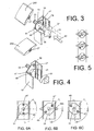
- FIG. 1 there are illustrated in an exploded arrangement the principal elements of a framed shutter assembly according to the invention.
- the whole structure is slidably suspended from an overhead top rail 1, which will be attached to a building structure in a conventional manner.
- Retained in the top rail 1 are wheeled suspension runners 3 for translational movement along the length of the top rail 1.
- Suspended from the suspension runner 3 is a runner plate 5.
- This runner plate 5 will be fixedly retained in top horizintal frame member 7, which may be covered by cover 9 against the ingress of dirt.
- At the bottom of the assembly there is a horizontal bottom frame member 11, which preferably can be similar in shape to the horizontal top frame member 7.
- a bottom guide 13 for guiding the framed shutter assembly along a bottom rail 15.
- the horizontal bottom frame member 11 can be closed by a bottom cover 17.
- the bottom guide 13 will be explained in further detail in reference to Figures 13-15.
- the bottom cover 17 has apertures 17a, 17b to allow portions of the bottom guide 13 to protrude from the bottom frame member 11.
- the top cover 9 has an aperture 9a to allow a portion of the runner plate 5 to protrude from the top frame member 7.
- a vertical frame member 19 is provided to connect the top and bottom frame members 7, 11 which is accomplished by screws 21.
- the vertical frame member 19 is also preferably provided with a vertical side cover 23.
- FIG 2 in an exploded arrangement shows a first embodiment of fin 25A.
- the fin 25A is formed as an extrusion having a continuous cross section. Centrally of this cross section the fin 25A has cavity formation 27 for non-rotatably receiving a pivot pin 33.
- the open end of the fin 25A on both sides of the central cavity formation 27 is closed by a pair of similar end caps 29.
- the vertical frame member 19 is provided with an opening 19A in register with the central cavity formation 27 and that a rotatable disc 31 with a pivot pin 33 for engaging the central cavity formation 27 engages through the opening 19A.
- the disc 31 is only partly circular in shape for a purpose that will now be explained in reference to Figures 3 and 4.
- FIG. 3 Shown in Figure 3 in dotted lines is a first position of the rotatable disc 31 before insertion into the vertical frame member 19.
- the flattened sides 35 and 37 of the disc 31 will pass ridges 39 and 41 on opposite sides of the vertical frame member 19 when the disc member 31 is moved in the direction of arrow 43.
- the pin 33 protrudes through the aperture 19A (not shown in Figure 3) and the fin 25A can be slid on with its central cavity formation 27 non-rotatably engaging the pin 33, so that it may only rotate together with the disc member 31.
- Rotation of the disc member 31 in the direction of arrow 45 will lock the disc member 31 behind the ridges 39 and 41.
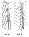
- FIGs 6A through 6B show again the sequence of rotating the disc member 31 clockwise from the insertion position into the horizontal open position of the fin 25A (Fig 6B) and from the open horizontal position into the closed position (Fig 6C). It is further shown in Figs 2 through 6C, that the disc member 31 has first and second outwardly projecting pins 47 and 49. The purpose of the first and second pins 47 and 49 will now be explained in reference to Figures 7 and 8.
- FIG. 7 a partly assembled side portion of the framed shutter assembly is shown.
- a first coupling strip 51 is shown mounted and engaging a first pin 47 on each of a number of successive disc members 31. Since the number of fins 25A can vary substantially with the height of framed shutter assemblies coupling strips would normally need to be available for each possible number of fins. Since this is expensive and cumbersome the present invention proposes the use of a fixed length of coupling strip, while using a plurality of these in assembling framed shutter assemblies.
- an assembly lock 59 may be fitted in the manner of a coupling strip to a few of the second pins 49. Pivotal movement if the vanes will then be limited between two positions in which the assembly lock 59 abuts a confronting one of the coupling strips 51, 53, 55. This corresponds to the end positions as illustrated in Figures 6A and 6B.
- Figure 9 shows an alternative embodiment of fin 25B, such as a solid wooden fin.
- fin 25B such as a solid wooden fin.
- similar vertical frame members 19 are used which have equally spaced apertures 19A to receive a drive disk 65 with a central pivot pin 67 protruding through the aperture 19A.
- the pivot pin 67 is shaped to snap-fit into a central opening 69 or 71 of the respective end cap 61 or 63.
- the drive discs can be given a shape that allows their insertion between the ribs 39 and 41 in all angular positions and this can be a full circular shape as shown in Figure 9.
- the vertical frame member 19 can again be closed with a cover 23.
- FIG 10 shows the attachment of a runner 3 to the horizontal top frame member 7 using the runner plate 5.
- the top frame member 7 is provided with internal, partly circular formations 73 and 75 extending inwardly from opposite vertical walls of the top frame member 7.
- a first function of these formations 73 and 75 is to receive the screw fasteners 21 with which the vertical frame members 19 are connected to the top frame member 7 (see Figure 1).
- a further function of these formations 73 and 75 is to retain the runner plate 5 in an adjustable fashion along the length of the top frame member 7, where by way of example it can be clamped between the formations 73, 75 and a lower web 77 of the top frame member 7.
- a clamping screw 79 is provided.
- washers like 81 and 83, may be provided in clamping the runner plate 5 against the formations 73 and 75 in the top frame member 7, as is illustrated in Figure 11.
- the runner 3 is affixed to the runner plate 5, and thereby to the top frame member 7, in a height adjustable way to compensate for any mal-alignments of the top rail 1 from the horizontal. It may also be necessary to compensate for small deviations in the squareness of the sliding panels themselves.
- a runner fixing component 85 is rotatably journalled in the runner plate 5.
- the runner fixing component 85 has a length by which its upper end extends above the horizontal frame member 7. This upper end 87 has diametrically opposite flats, to allow it to be held against rotation by a wrench or like tool (not shown).
- the runner fixing component 85 further has an internally threaded screw receiving bore 89 in which screw stud 91 of the runner 3 is screw-rotatably received. Screwed on the screw stud 91 is a locking nut 93 which is useful to lock the runner fixing component 85 in position once the desired height adjustment has been achieved.
- Figure 12 shows how the distance D can be adjusted by rotating the runner fixing component in either of the directions indicated by arrow 95, moving the top frame member 7 closer to or away from the overhead track 1.
- Figures 13, 14 and 15 serve to illustrate the bottom guide runner assembly 13 as mounted to the horizontal bottom frame member 11.
- the bottom frame member 11 is preferably identical to the top frame member 7 and has identical formations 101 and 103 on its opposite inner walls.
- the bottom guide 13 has an upper bottom plate 105 and a lower bottom plate 107.
- the upper bottom plate 105 is inserted upwardly of the inner formations 101, and 103 of the bottom frame member 11.
- the lower bottom plate 107 is inserted below the inner formations 101 and 103.
- the upper bottom plate has screw threaded bores 109 and 111.
- the lower bottom plate 107 has screw threaded bores 113 and 115 and through bores 117 and 119 which are in register with the threaded bores 109 and 111 in the upper bottom plate 105.
- a shaft 121 Engageable in the screw threaded bore 113 is a shaft 121, preferably formed by a standard screw fastener, on which is rotatably received a roller 123.
- a locking nut 125 fixes the screw shaft 121 with respect to the lower bottom plate 107.
- washers such as 127 and 129 may be provided in accordance with accepted engineering practice.
- Figure 14 shows the roller 123 fitted to the lower bottom plate 107 and the mounting of a further roller 131 by means of a screw shaft 133 in the other screw threaded bore 115.
- FIG. 14 Also illustrated in Figure 14 is how further screw fasteners 135 and 137 are inserted in the through bores 117 and 113 in the lower bottom plate 107 to engage the threaded bores 109 and 111 respectively in the upper bottom plate 105 and clamp the upper and lower bottom plates together.
- Figure 15 further shows how the roller 123 and 131 are engaging opposite surfaces of a vertical flange 139 that is part of the bottom rail 15.
Landscapes
- Engineering & Computer Science (AREA)
- Civil Engineering (AREA)
- Structural Engineering (AREA)
- Operating, Guiding And Securing Of Roll- Type Closing Members (AREA)
- Grates (AREA)
Priority Applications (1)
| Application Number | Priority Date | Filing Date | Title |
|---|---|---|---|
| EP05252136A EP1586735A3 (fr) | 2004-04-05 | 2005-04-05 | Volet avec cadre avec des lamelles amovibles |
Applications Claiming Priority (3)
| Application Number | Priority Date | Filing Date | Title |
|---|---|---|---|
| EP04075999 | 2004-04-05 | ||
| EP04075999 | 2004-04-05 | ||
| EP05252136A EP1586735A3 (fr) | 2004-04-05 | 2005-04-05 | Volet avec cadre avec des lamelles amovibles |
Publications (2)
| Publication Number | Publication Date |
|---|---|
| EP1586735A2 true EP1586735A2 (fr) | 2005-10-19 |
| EP1586735A3 EP1586735A3 (fr) | 2010-12-22 |
Family
ID=34940720
Family Applications (1)
| Application Number | Title | Priority Date | Filing Date |
|---|---|---|---|
| EP05252136A Withdrawn EP1586735A3 (fr) | 2004-04-05 | 2005-04-05 | Volet avec cadre avec des lamelles amovibles |
Country Status (1)
| Country | Link |
|---|---|
| EP (1) | EP1586735A3 (fr) |
Cited By (2)
| Publication number | Priority date | Publication date | Assignee | Title |
|---|---|---|---|---|
| EP1995405A2 (fr) | 2007-05-21 | 2008-11-26 | GEZE GmbH | Installation de battant coulissant |
| CN106967944A (zh) * | 2016-01-14 | 2017-07-21 | 贵州西南工具(集团)有限公司 | 一种氮化炉零件放置料框架及其制作方法 |
Citations (4)
| Publication number | Priority date | Publication date | Assignee | Title |
|---|---|---|---|---|
| GB1356381A (en) | 1970-03-12 | 1974-06-12 | Jervis F R A | Hinged panel structures |
| EP0220355A1 (fr) | 1985-10-30 | 1987-05-06 | KIKAU S.r.l. | Volet |
| US6401391B2 (en) | 1997-12-15 | 2002-06-11 | Vinylbiltshutter Systems Inc. | Louver control in a movable louver assembly |
| US6675534B2 (en) | 2002-01-18 | 2004-01-13 | Shade-O-Matic Limited | Shutter with push/pull control for shutter blades |
Family Cites Families (7)
| Publication number | Priority date | Publication date | Assignee | Title |
|---|---|---|---|---|
| GB286106A (en) * | 1927-03-30 | 1928-03-01 | James Paul Griffiths | Improvements relating to louvre or other shutters for windows |
| EP0273885B1 (fr) * | 1986-12-30 | 1991-09-04 | METALLURGICA METRA TRAFILATI ALLUMINIO S.p.A. | Volet à un ou plusieurs battants, pivotants ou coulissants pourvus de lamelles fixes ou orientables |
| IT224867Z2 (it) * | 1989-12-12 | 1996-07-26 | Sergio Torresi | Supporto di estremita' e manovella di movimentazione,in materiale pla stico o simile,per lamelle o stecche orientabili,ad inserimento diretto e rapido su intelaiature premontate per serramenti a persiana. |
| AUPQ078299A0 (en) * | 1999-06-04 | 1999-06-24 | Metzen Louvres Pty Limited | A louvre system |
| US6449903B1 (en) * | 1999-12-29 | 2002-09-17 | Norb Borcherding | Snap-together shutters with moveable louvers |
| DE20100752U1 (de) * | 2001-01-15 | 2001-04-19 | Schüco International KG, 33609 Bielefeld | Lagerschiene für ein Lamellenregister und Lamellenregister |
| DE10103032A1 (de) * | 2001-01-24 | 2002-07-25 | Schwab Helmut | Klappladen mit horizontalen Lamellen und Lagerzapfen |
-
2005
- 2005-04-05 EP EP05252136A patent/EP1586735A3/fr not_active Withdrawn
Patent Citations (4)
| Publication number | Priority date | Publication date | Assignee | Title |
|---|---|---|---|---|
| GB1356381A (en) | 1970-03-12 | 1974-06-12 | Jervis F R A | Hinged panel structures |
| EP0220355A1 (fr) | 1985-10-30 | 1987-05-06 | KIKAU S.r.l. | Volet |
| US6401391B2 (en) | 1997-12-15 | 2002-06-11 | Vinylbiltshutter Systems Inc. | Louver control in a movable louver assembly |
| US6675534B2 (en) | 2002-01-18 | 2004-01-13 | Shade-O-Matic Limited | Shutter with push/pull control for shutter blades |
Cited By (6)
| Publication number | Priority date | Publication date | Assignee | Title |
|---|---|---|---|---|
| EP1995405A2 (fr) | 2007-05-21 | 2008-11-26 | GEZE GmbH | Installation de battant coulissant |
| DE102007023797A1 (de) | 2007-05-21 | 2008-11-27 | Geze Gmbh | Schiebeflügelanlage |
| DE102007023797B4 (de) * | 2007-05-21 | 2009-05-07 | Geze Gmbh | Schiebeflügelanlage |
| EP1995405A3 (fr) * | 2007-05-21 | 2013-10-23 | GEZE GmbH | Installation de battant coulissant |
| CN106967944A (zh) * | 2016-01-14 | 2017-07-21 | 贵州西南工具(集团)有限公司 | 一种氮化炉零件放置料框架及其制作方法 |
| CN106967944B (zh) * | 2016-01-14 | 2023-11-14 | 贵州西南工具(集团)有限公司 | 一种氮化炉零件放置料框架及其制作方法 |
Also Published As
| Publication number | Publication date |
|---|---|
| EP1586735A3 (fr) | 2010-12-22 |
Similar Documents
| Publication | Publication Date | Title |
|---|---|---|
| US6145251A (en) | Adjustable shutter assembly and slat control mechanism using a control gear and gear engaging positioner | |
| EP0428589B1 (fr) | Systeme d'assemblage | |
| US6675534B2 (en) | Shutter with push/pull control for shutter blades | |
| EP0501803A1 (fr) | Mécanisme de crémone | |
| US5967215A (en) | One-and two-way pet screen door kit | |
| CN110630146B (zh) | 一种装配式建筑门窗 | |
| US4513555A (en) | Barn door framing system | |
| AU736815B2 (en) | Louvre window clip assembly | |
| US5701813A (en) | Pet door for screen applications | |
| EP1586735A2 (fr) | Volet avec cadre avec des lamelles amovibles | |
| JP3726384B2 (ja) | シャッターカーテンの吊元構造 | |
| EP0538540B1 (fr) | Elément de connexion mécanique pour unité modulaire de meubles, notamment des tableaux de distribution de type ouvert ou étanche | |
| JP3047941U (ja) | スライド雨戸 | |
| JPH0725431Y2 (ja) | 目隠し用部材 | |
| JP4183559B2 (ja) | クレセント受け、およびこれを備えたサッシ窓 | |
| CA2282237C (fr) | Ensemble de volet ajustable et mecanisme de commande de bec | |
| KR102788089B1 (ko) | 안쪽열림 여닫이창호용 방범·방충창 | |
| GB2286418A (en) | Spring assembly for sash windows | |
| JPS6244074Y2 (fr) | ||
| AU618398B2 (en) | Connection system | |
| JP3926453B2 (ja) | 網戸の取付装置 | |
| JP4031126B2 (ja) | 扉 | |
| JPS6036717Y2 (ja) | 窓 | |
| JP2859858B2 (ja) | 両開蝶番 | |
| JPS5838149Y2 (ja) | 金属製クロゼツト・ドア |
Legal Events
| Date | Code | Title | Description |
|---|---|---|---|
| PUAI | Public reference made under article 153(3) epc to a published international application that has entered the european phase |
Free format text: ORIGINAL CODE: 0009012 |
|
| AK | Designated contracting states |
Kind code of ref document: A2 Designated state(s): AT BE BG CH CY CZ DE DK EE ES FI FR GB GR HU IE IS IT LI LT LU MC NL PL PT RO SE SI SK TR |
|
| AX | Request for extension of the european patent |
Extension state: AL BA HR LV MK YU |
|
| PUAL | Search report despatched |
Free format text: ORIGINAL CODE: 0009013 |
|
| AK | Designated contracting states |
Kind code of ref document: A3 Designated state(s): AT BE BG CH CY CZ DE DK EE ES FI FR GB GR HU IE IS IT LI LT LU MC NL PL PT RO SE SI SK TR |
|
| AX | Request for extension of the european patent |
Extension state: AL BA HR LV MK YU |
|
| 17P | Request for examination filed |
Effective date: 20110523 |
|
| AKX | Designation fees paid |
Designated state(s): AT BE BG CH CY CZ DE DK EE ES FI FR GB GR HU IE IS IT LI LT LU MC NL PL PT RO SE SI SK TR |
|
| GRAP | Despatch of communication of intention to grant a patent |
Free format text: ORIGINAL CODE: EPIDOSNIGR1 |
|
| STAA | Information on the status of an ep patent application or granted ep patent |
Free format text: STATUS: THE APPLICATION IS DEEMED TO BE WITHDRAWN |
|
| 18D | Application deemed to be withdrawn |
Effective date: 20120914 |