EP1586738A2 - Méthode et dispositif de refroidissement des aubes des turbine - Google Patents
Méthode et dispositif de refroidissement des aubes des turbine Download PDFInfo
- Publication number
- EP1586738A2 EP1586738A2 EP05250397A EP05250397A EP1586738A2 EP 1586738 A2 EP1586738 A2 EP 1586738A2 EP 05250397 A EP05250397 A EP 05250397A EP 05250397 A EP05250397 A EP 05250397A EP 1586738 A2 EP1586738 A2 EP 1586738A2
- Authority
- EP
- European Patent Office
- Prior art keywords
- cooling
- airfoil
- chamber
- sidewall
- chambers
- Prior art date
- Legal status (The legal status is an assumption and is not a legal conclusion. Google has not performed a legal analysis and makes no representation as to the accuracy of the status listed.)
- Withdrawn
Links
Images

Classifications
-
- F—MECHANICAL ENGINEERING; LIGHTING; HEATING; WEAPONS; BLASTING
- F01—MACHINES OR ENGINES IN GENERAL; ENGINE PLANTS IN GENERAL; STEAM ENGINES
- F01D—NON-POSITIVE DISPLACEMENT MACHINES OR ENGINES, e.g. STEAM TURBINES
- F01D5/00—Blades; Blade-carrying members; Heating, heat-insulating, cooling or antivibration means on the blades or the members
- F01D5/12—Blades
- F01D5/14—Form or construction
- F01D5/18—Hollow blades, i.e. blades with cooling or heating channels or cavities; Heating, heat-insulating or cooling means on blades
- F01D5/187—Convection cooling
-
- Y—GENERAL TAGGING OF NEW TECHNOLOGICAL DEVELOPMENTS; GENERAL TAGGING OF CROSS-SECTIONAL TECHNOLOGIES SPANNING OVER SEVERAL SECTIONS OF THE IPC; TECHNICAL SUBJECTS COVERED BY FORMER USPC CROSS-REFERENCE ART COLLECTIONS [XRACs] AND DIGESTS
- Y02—TECHNOLOGIES OR APPLICATIONS FOR MITIGATION OR ADAPTATION AGAINST CLIMATE CHANGE
- Y02T—CLIMATE CHANGE MITIGATION TECHNOLOGIES RELATED TO TRANSPORTATION
- Y02T50/00—Aeronautics or air transport
- Y02T50/60—Efficient propulsion technologies, e.g. for aircraft
Definitions
- This invention relates generally to gas turbine engine rotor blades and, more particularly, to methods and apparatus for reducing turbine blade temperatures.
- Gas turbine engine rotor blades typically include airfoils having leading and trailing edges, a pressure side, and a suction side.
- the pressure and suction sides are connected at the airfoil leading and trailing edges, and span radially between the airfoil root and the tip.
- combustion gases impacting the rotating rotor blades transfer heat into the airfoils. Over time, continued exposure to high temperature combustion gases may thermally fatigue the airfoil.
- known airfoils include an internal cooling circuit which channels cooling fluid through the airfoil.
- at least some known rotor blades channel compressor bleed air into a cavity defined between the sidewalls, to convectively cool the sidewalls.
- at least some known cooling circuits utilize shear-jet cooling wherein a plurality of shear-jet openings channel cooling fluid along an inner surface of the sidewalls to facilitate cooling the sidewalls. Additional cooling cavities can be accomplished using impingement cooling wherein impingement inserts channel cooling fluid through impingement jet arrays against the inner surface of the airfoil's leading edge to facilitate cooling the airfoil along the leading edge.
- impingement cooling wherein impingement inserts channel cooling fluid through impingement jet arrays against the inner surface of the airfoil's leading edge to facilitate cooling the airfoil along the leading edge.
- a method for fabricating a rotor blade for a gas turbine engine.
- the rotor blade includes an airfoil having a first sidewall and a second sidewall connected together at a leading edge and a trailing edge, such that a cavity is formed therebetween.
- the method includes forming a plurality of rib walls that extend at least partially between the first and second sidewalls, wherein the rib walls define at least one cooling circuit, wherein each cooling circuit includes at least three cooling chambers, wherein a first of the cooling chambers supplies cooling fluid to the airfoil cavity, and forming at least one row of openings within at least one of the rib walls extending between adjacent cooling chambers, such that the remaining cooling chambers are coupled in flow communication to the first cooling chamber via the openings.
- an airfoil for a gas turbine engine.
- the airfoil includes a first sidewall and a second sidewall coupled together at a leading edge and a trailing edge, such that a cavity is defined therebetween.
- a plurality of rib walls extend at least partially between the first and second sidewalls, wherein the plurality of rib walls define at least one cooling circuit having at least three cooling chambers.
- At least one row of openings extend through at least one of the rib walls, wherein a first of the cooling chambers supplies cooling fluid to the cavity, and the remaining cooling chambers are coupled in flow communication with the first cooling chamber via the openings.
- a gas turbine engine in a further aspect, includes a plurality of rotor blades, each rotor blade has an airfoil that includes a leading edge, a trailing edge, a first sidewall and a second sidewall coupled together at the leading and trailing edges such that a cavity is defined therebetween, a plurality of rib walls extending at least partially between the first and second sidewalls, and at least one row of openings extending through at least one of the rib walls.
- the plurality of rib walls define at least one cooling circuit having at least three cooling chambers, wherein a first of the cooling chambers supplies cooling fluid to the cavity, wherein the remaining cooling chambers are coupled in flow communication with the first cooling chamber via said openings.
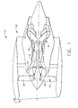
- FIG. 1 is a schematic illustration of a gas turbine engine 10 including a fan assembly 12, a high pressure compressor 14, and a combustor 16.
- Engine 10 also includes a high pressure turbine 18, a low pressure turbine 20, and a booster 22.
- Fan assembly 12 includes an array of fan blades 24 extending radially outward from a rotor disc 26.
- Engine 10 has an intake side 28 and an exhaust side 30.
- engine 10 is a CT7 engine commercially available from General Electric Aircraft Engines, Cincinnati, Ohio.
- Airflow (not shown in Figure 1) from combustor 16 drives turbines 18 and 20, and turbine 20 drives fan assembly 12.
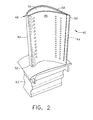
- FIG 2 is a perspective view of a rotor blade 40 that may be used with gas turbine engine 10 (shown in Figure 1).
- Figure 3 is a cross-sectional view of rotor blade 40.
- a plurality of rotor blades 40 form a high pressure turbine rotor blade stage (not shown) of gas turbine engine 10.
- Each rotor blade 40 includes a hollow airfoil 42 and an integral dovetail 43 used for mounting airfoil 42 to a rotor disk (not shown) in a known manner.
- Airfoil 42 includes a first sidewall 44 and a second sidewall 46.
- First sidewall 44 is convex and defines a suction side of airfoil 42
- second sidewall 46 is concave and defines a pressure side of airfoil 42.
- Sidewalls 44 and 46 are connected together at a leading edge 48 and at an axially-spaced trailing edge 50 of airfoil 42 that is downstream from leading edge 48.
- Airfoil 42 includes a plurality of film holes 51 that are spaced radially along sidewall 46 and between an airfoil tip 54 and a blade root 52 for discharging cooling fluid from airfoil 42 to facilitate cooling an outer surface 53 of airfoil 42.
- Airfoil 42 also includes a plurality of trailing edge slots 55 spaced radially between airfoil tip 54 and blade root 52 along trailing edge 50 for discharging cooling fluid from airfoil 42 to facilitate cooling airfoil trailing edge 50. Heat transfer enhanced by film holes 51 and trailing edge slots 55 facilitates cooling along airfoil outer surface 53.
- First and second sidewalls 44 and 46 extend longitudinally from blade root 52 positioned adjacent dovetail 43 to airfoil tip 54 which defines a radially outer boundary of an internal cavity 56.
- Cavity 56 is defined within airfoil 42 between sidewalls 44 and 46.
- cavity 56 is divided into a plurality of cooling chambers 58 which form cooling circuits 60 that target specific areas of airfoil 42.
- three cooling circuits 60 are provided.
- cooling circuits 60 include a leading edge circuit 62 for cooling leading edge 48, a pressure side circuit 64 for cooling pressure sidewall 46, and a suction side circuit 66 for cooling suction sidewall 44.
- airfoil 42 has more or less than three cooling circuits 60.
- Cavity 56 includes a plurality of rib walls 70 extending therein.
- rib walls 70 extend radially between airfoil tip 54 and blade root 52, and, in conjunction with airfoil sidewalls 44 and 46, define cooling chambers 58.
- rib walls 70 extend only partially between airfoil tip 54 and blade root 52.
- airfoil sidewall 44 and/or 46 and rib walls 70 are fabricated with a substantially equal wall thickness T 1 .
- each cooling chamber 58 is bordered by at least one airfoil sidewalls 44 and/or 46, and/or by at least one rib wall 70.
- cooling chambers 58 are defined by an inner surface 72 of at least one rib wall 70, and/or an inner surface 74 of at least one airfoil sidewall 44 and/or 46.
- Each cooling circuit 60 includes at least one feed chamber 80, at least one transition chamber 82, and at least one ejection chamber 84.
- chambers 80, 82, and/or 84 are separated from one another by rib walls 70, and are coupled together in flow communication by a row of openings 88, or slots, formed in a rib wall 70 extending between adjacent chambers 58.
- Each row of openings 88 is spaced across each rib wall 70 between blade root 52 and airfoil tip 54.
- Each transition chamber 82 and ejection chamber 84 extend substantially through airfoil 42 between blade root 52 and airfoil tip 54.
- feed chamber 80 extends through blade root 52 and into rotor blade dovetail portion 43 wherein feed chamber 80 is coupled in flow communication with a feed passage (not shown) which supplies a cooling fluid, such as air, to each respective circuit 60 through feed chamber 80.
- cooling circuit 60 supplies a substantially constant flow of cooling fluid to cavity 56 which is dispersed serially through chambers 80, 82, and 84 and along inner surface 74 of airfoil sidewalls 44 and 46. Cooling fluid is eventually ejected from cooling circuit via film holes 51 and/or trailing edge slots 55.
- Pressure side circuit 64 utilizes a shear jet cooling process wherein a highspeed shear jet 100 directs cooling fluid across inner surface 74 of sidewall 46.
- pressure side circuit 64 includes a pressure side feeding chamber 90, a pressure side transition chamber 92, and a pressure side ejection chamber 94.
- a first row of openings 96 are defined in the rib wall 70 which separates feeding chamber 90 and transition chamber 94, and a second row of openings 98 are formed in the rib wall 70 separating transition chamber 92 and ejection chamber 94.
- openings 96 and 98 are adjacent pressure sidewall inner surface 74 such that cooling fluid discharged from openings 96 and/or 98 facilitates cooling airfoil sidewall 46, thereby reducing an operating temperature of sidewall 46.
- Cooling fluid is supplied to pressure side circuit 64 via feeding chamber 90 and flows as a shear jet, indicated by arrows 100, from feeding chamber 90 through openings 96 into transition chamber 92. Specifically, cooling fluid supplied to transition chamber 92 flows along sidewall inner surface 74 to facilitate cooling of airfoil sidewall 46. Shear jet 100 is discharged from transition chamber 92 through openings 98 into ejection chamber 94, wherein the cooling fluid flows along sidewall inner surface 74 to facilitate additional cooling of airfoil sidewall 46. Shear jet 100 is then discharged from airfoil 42 through a row of film holes 51 extending through pressure sidewall 46.
- pressure side circuit 64 includes feeding chamber 90 and ejection chamber 94, but does not include any transition chambers 92.
- pressure side circuit 64 includes a plurality of transition chambers 92 coupled together in flow communication between feeding chamber 90 and ejection chamber 94.
- pressure side circuit includes two or more ejection chambers 94 coupled together in flow communication, such that pressure side film holes 51 receive cooling fluid discharged from a plurality of cooling chambers 58.
- airfoil inner surface 74 includes cooling enhancement features (not shown), such as, for example, turbulators, dimples, bumps, or a combination of these, to facilitate enhanced cooling and heat transfer.
- Suction side circuit 66 utilizes a shear jet cooling process wherein a highspeed shear jet 130 directs cooling fluid across inner surface 74 of suction sidewall 44.
- suction side circuit 66 includes a suction side feeding chamber 110, two suction side transition chambers 112 and 114, and two suction side ejection chambers 116 and 118, wherein a row of openings 120, 122, 124, and 126 are defined by the rib walls 70 which separate adjacent chambers 58, such as chambers 110, 112, 114, 116, and 118.
- a first row of openings 120 extends between feeding chamber 110 and a first transition chamber 112
- a second row of openings 122 extends between first transition chamber 112 and second transition chamber 114
- a third row of openings 124 extends between second transition chamber 114 and first ejection chamber 116
- a forth row of openings 126 extends between first ejection chamber 116 and second ejection chamber 118.
- openings 120, 122, 124, and 126 are positioned adjacent suction sidewall inner surface 74 such that cooling fluid discharged from openings 120, 122, 124, and 126, facilitates cooling airfoil sidewall 44.
- Cooling fluid is supplied to suction side circuit 66 via feeding chamber 110 and flows as shear jet 130 from feeding chamber 110 through openings 120 into first transition chamber 112. Specifically, cooling fluid supplied to first transition chamber 112 flows along sidewall inner surface 74 to facilitate cooling airfoil sidewall 44. Shear jet 130 is discharged from transition chamber 112 through openings 122 into second transition chamber 114, wherein the cooling fluid flows along sidewall inner surface 74 to facilitate additional cooling of sidewall 44. Shear jet 130 is then discharged from second transition chamber 114 through openings 124 into first ejection chamber 116. Cooling fluid entering first ejection chamber 116 flows along sidewall inner surface 74 to facilitate cooling of airfoil sidewall 44.
- a portion 131 of cooling fluid is then channeled from suction side circuit 66 through a row of pressure side film holes 132 extending through pressure sidewall 46.
- the remaining cooling fluid flows as a shear jet 133 from first ejection chamber 116 through openings 126 into second ejection chamber 118.
- Cooling fluid entering second ejection chamber 118 is channeled along sidewall inner surface 74 to facilitate additional cooling of airfoil sidewall 44.
- Shear jet 134 is then discharged from airfoil cavity 56 through trailing edge slots 55 extending through airfoil 42 at trailing edge 50.
- suction side circuit 66 includes feeding chamber 110 and ejection chamber 118, but does not include transition chambers 112 and 114 and ejection chamber 116.
- suction side circuit 66 includes one transition chamber 112 or 114 coupled in flow communication between feeding chamber 110 and ejection chambers 116 and 118.
- suction side circuit 66 has one ejection chamber 116 or 118 coupled in flow communication to feed chamber 110 and transition chambers 112 and 114, such that suction side film holes 132 only receive cooling fluid discharged from one cooling chamber 116 or 118.
- airfoil inner surface 74 includes cooling enhancement features, such as, for example, turbulators, dimples, bumps, or a combination of these, to facilitate enhanced cooling and heat transfer.
- airfoil 42 includes a leading edge circuit 62 having a leading edge feeding chamber 140 and a leading edge ejection chamber 142, and utilizes a conventional cold-bridge impingement cooling process.
- a row of openings 144, or slots, are defined by the rib wall 70 which separates feeding and ejection chambers 140 and 142, respectively.
- Cooling fluid is discharged from feeding chamber 140 through openings 144 into ejection chamber 142. Cooling fluid discharged from opening 144 flows towards leading edge inner surface 74. Cooling fluid is deflected towards the pressure and suction sidewalls 44 and 46, respectively, wherein the cooling fluid flows along sidewall inner surface 74 to facilitate additional cooling of airfoil sidewalls 44 and 46.
- a pressure side film cooling hole 146 and a suction side film cooling hole 148 extend through sidewalls 44 and 46, respectively. Cooling fluid is discharged from cavity 56 via film cooling holes 146 and 148, respectively, to facilitate further cooling of sidewalls 44 and 46.
- feeding chambers 90, 110 and 140 extend within cavity 56 from the feed passage (not shown) and are positioned adjacent one another. In the exemplary embodiment, feeding chambers 90, 110, and 140 are located near leading edge 48 which is the thickest section of airfoil 42. This construction provides colder, uniform temperatures in the thickest section of airfoil 42.
- airfoil 42 includes a first purge chamber 150 and a second purge chamber 152.
- Purge chambers 150 and 152 are defined by rib walls 70 and are included in airfoil cavity 56 for structural support. Purge chambers 150 and 152 are not actively cooled by cooling fluid as are the other chambers 58, but rather are cooled by a near wall impingement process.
- the rib walls 70 defining purge chambers 150 and/or 152 also define cooling chambers 58, such as chambers 90, 92, 94, 110, 112, and 114. As such, when cooling fluid is transferred through cooling chambers 58, as described above, heat is transferred from rib walls 70 to the cooling fluid thereby reducing the operating temperature of rib walls 70.
- purge chambers 150 and/or 152 are cooled by the decrease in the operating temperature of rib walls 70.
- purge chambers 150 and 152 are further cooled when purge air is supplied to purge chambers 150 and 152.
- more than two purge chambers are provided in airfoil cavity 56.
- less than two purge chambers are provided in airfoil cavity 56.
- rotor blade 40 is fabricated by a casting process using a plurality of cores formed together into a single piece core 166 and, in the exemplary embodiment, includes three separate cores 160, 162, and 164, respectively.
- First core 160 is defined by pressure side circuit 64 and leading edge circuit 62.
- Second core 162 is defined by suction side circuit 66, and
- third core 164 is defined by purge chambers 150 and 152.
- Cores 160, 162, and 164 are assembled together to form a single core 166 for the casting process.
- Chambers 58, 150 and 152 are sufficiently large for making ceramic cores 160, 162, and/or 164 for casting.
- the above-described rotor blade is cost-effective and highly reliable.
- the rotor blade includes an airfoil having a number of cooling circuits which target cooling on the leading edge, pressure side and suction side of the airfoil.
- a number of cooling techniques are employed to cool the exterior sidewalls of the airfoil, such as impingement cooling, near-wall cooling, and shear-jet cooling. Additional cooling enhancement features can be designed into the inner sidewalls of the airfoil. As a result, cooler operating temperatures within the rotor blade facilitate extending a useful life of the rotor blades in a cost-effective and reliable manner.
Landscapes
- Engineering & Computer Science (AREA)
- Mechanical Engineering (AREA)
- General Engineering & Computer Science (AREA)
- Turbine Rotor Nozzle Sealing (AREA)
Applications Claiming Priority (2)
| Application Number | Priority Date | Filing Date | Title |
|---|---|---|---|
| US10/824,283 US7217092B2 (en) | 2004-04-14 | 2004-04-14 | Method and apparatus for reducing turbine blade temperatures |
| US824283 | 2004-04-14 |
Publications (1)
| Publication Number | Publication Date |
|---|---|
| EP1586738A2 true EP1586738A2 (fr) | 2005-10-19 |
Family
ID=34940394
Family Applications (1)
| Application Number | Title | Priority Date | Filing Date |
|---|---|---|---|
| EP05250397A Withdrawn EP1586738A2 (fr) | 2004-04-14 | 2005-01-26 | Méthode et dispositif de refroidissement des aubes des turbine |
Country Status (3)
| Country | Link |
|---|---|
| US (1) | US7217092B2 (fr) |
| EP (1) | EP1586738A2 (fr) |
| JP (1) | JP2005299637A (fr) |
Cited By (10)
| Publication number | Priority date | Publication date | Assignee | Title |
|---|---|---|---|---|
| EP1882819A1 (fr) * | 2006-07-18 | 2008-01-30 | United Technologies Corporation | Microcircuits pour pales de turbine intégrés dans la plate-forme, la pointe, et l'aube |
| US7553131B2 (en) | 2006-07-21 | 2009-06-30 | United Technologies Corporation | Integrated platform, tip, and main body microcircuits for turbine blades |
| EP1793085A3 (fr) * | 2005-12-05 | 2012-05-30 | General Electric Company | Aube de turbine à gaz à circuits de refroidissement en serpentine |
| EP2659095A4 (fr) * | 2010-12-30 | 2016-01-27 | Rolls Royce Nam Tech Inc | Turbine à gaz et circuit d'écoulement refroidi associé |
| WO2016122483A1 (fr) * | 2015-01-28 | 2016-08-04 | Siemens Aktiengesellschaft | Profil de turbine avec système de refroidissement par impact de bord de fuite |
| WO2016133511A1 (fr) * | 2015-02-19 | 2016-08-25 | Siemens Energy, Inc. | Profil de turbine équipé d'un système de refroidissement interne formé à partir d'une paroi interne interrompue formant des cavités inactives |
| EP3418495A1 (fr) * | 2017-06-22 | 2018-12-26 | United Technologies Corporation | Dispositif de flux de gaz comprenant des plénums à perles minuscules |
| US11149550B2 (en) | 2019-02-07 | 2021-10-19 | Raytheon Technologies Corporation | Blade neck transition |
| EP3954864A1 (fr) * | 2020-08-10 | 2022-02-16 | Raytheon Technologies Corporation | Passages de refroidissement de pale/d'aube |
| EP4428338A3 (fr) * | 2023-03-07 | 2025-02-26 | RTX Corporation | Aubes de moteur de turbine avec refroidissement par film et procédé de fabrication |
Families Citing this family (21)
| Publication number | Priority date | Publication date | Assignee | Title |
|---|---|---|---|---|
| FR2893974B1 (fr) * | 2005-11-28 | 2011-03-18 | Snecma | Circuit de refroidissement central pour aube mobile de turbomachine |
| US7695246B2 (en) * | 2006-01-31 | 2010-04-13 | United Technologies Corporation | Microcircuits for small engines |
| GB2440127B (en) * | 2006-06-07 | 2008-07-09 | Rolls Royce Plc | A turbine blade for a gas turbine engine |
| US7862299B1 (en) * | 2007-03-21 | 2011-01-04 | Florida Turbine Technologies, Inc. | Two piece hollow turbine blade with serpentine cooling circuits |
| JP4930276B2 (ja) * | 2007-08-21 | 2012-05-16 | 株式会社Ihi | 高温部品の内面冷却構造 |
| US20140075947A1 (en) * | 2012-09-18 | 2014-03-20 | United Technologies Corporation | Gas turbine engine component cooling circuit |
| US9267381B2 (en) | 2012-09-28 | 2016-02-23 | Honeywell International Inc. | Cooled turbine airfoil structures |
| US9995148B2 (en) | 2012-10-04 | 2018-06-12 | General Electric Company | Method and apparatus for cooling gas turbine and rotor blades |
| US9297267B2 (en) * | 2012-12-10 | 2016-03-29 | General Electric Company | System and method for removing heat from a turbine |
| US10605096B2 (en) * | 2016-05-12 | 2020-03-31 | General Electric Company | Flared central cavity aft of airfoil leading edge |
| US10378364B2 (en) | 2017-11-07 | 2019-08-13 | United Technologies Corporation | Modified structural truss for airfoils |
| US10871074B2 (en) * | 2019-02-28 | 2020-12-22 | Raytheon Technologies Corporation | Blade/vane cooling passages |
| US11459897B2 (en) | 2019-05-03 | 2022-10-04 | Raytheon Technologies Corporation | Cooling schemes for airfoils for gas turbine engines |
| US11111857B2 (en) | 2019-07-18 | 2021-09-07 | Raytheon Technologies Corporation | Hourglass airfoil cooling configuration |
| US11220912B2 (en) | 2020-04-16 | 2022-01-11 | Raytheon Technologies Corporation | Airfoil with y-shaped rib |
| US11629602B2 (en) | 2021-06-17 | 2023-04-18 | Raytheon Technologies Corporation | Cooling schemes for airfoils for gas turbine engines |
| US11905849B2 (en) | 2021-10-21 | 2024-02-20 | Rtx Corporation | Cooling schemes for airfoils for gas turbine engines |
| EP4343116A3 (fr) | 2022-09-26 | 2024-04-17 | RTX Corporation | Profils aérodynamiques à cavités de refroidissement à lobes |
| US12196095B2 (en) * | 2022-11-29 | 2025-01-14 | Rtx Corporation | Gas turbine engine component having an airfoil with internal cross-ribs |
| US12540552B2 (en) * | 2023-03-07 | 2026-02-03 | Rtx Corporation | Airfoils with axial leading edge impingement slots |
| US12281595B1 (en) * | 2023-10-13 | 2025-04-22 | Rtx Corporation | Turbine blade with boomerang shaped wall cooling passages |
Family Cites Families (19)
| Publication number | Priority date | Publication date | Assignee | Title |
|---|---|---|---|---|
| CH584346A5 (fr) * | 1974-11-08 | 1977-01-31 | Bbc Sulzer Turbomaschinen | |
| GB2163219B (en) * | 1981-10-31 | 1986-08-13 | Rolls Royce | Cooled turbine blade |
| US4515526A (en) * | 1981-12-28 | 1985-05-07 | United Technologies Corporation | Coolable airfoil for a rotary machine |
| JPS62271902A (ja) * | 1986-01-20 | 1987-11-26 | Hitachi Ltd | ガスタ−ビン冷却翼 |
| US5002460A (en) * | 1989-10-02 | 1991-03-26 | General Electric Company | Internally cooled airfoil blade |
| US5704763A (en) * | 1990-08-01 | 1998-01-06 | General Electric Company | Shear jet cooling passages for internally cooled machine elements |
| JPH0778361B2 (ja) * | 1991-09-02 | 1995-08-23 | ゼネラル・エレクトリック・カンパニイ | 内腔形成リブを通して直列衝突冷却するタービンブレード・エアーホイル |
| US5246340A (en) * | 1991-11-19 | 1993-09-21 | Allied-Signal Inc. | Internally cooled airfoil |
| JPH05195704A (ja) * | 1992-01-22 | 1993-08-03 | Hitachi Ltd | タービン翼及びガスタービン |
| US5484258A (en) * | 1994-03-01 | 1996-01-16 | General Electric Company | Turbine airfoil with convectively cooled double shell outer wall |
| US5603606A (en) * | 1994-11-14 | 1997-02-18 | Solar Turbines Incorporated | Turbine cooling system |
| US5820337A (en) * | 1995-01-03 | 1998-10-13 | General Electric Company | Double wall turbine parts |
| US5536143A (en) * | 1995-03-31 | 1996-07-16 | General Electric Co. | Closed circuit steam cooled bucket |
| US6036441A (en) * | 1998-11-16 | 2000-03-14 | General Electric Company | Series impingement cooled airfoil |
| GB0025012D0 (en) * | 2000-10-12 | 2000-11-29 | Rolls Royce Plc | Cooling of gas turbine engine aerofoils |
| US6422821B1 (en) * | 2001-01-09 | 2002-07-23 | General Electric Company | Method and apparatus for reducing turbine blade tip temperatures |
| US6382913B1 (en) * | 2001-02-09 | 2002-05-07 | General Electric Company | Method and apparatus for reducing turbine blade tip region temperatures |
| US6602052B2 (en) * | 2001-06-20 | 2003-08-05 | Alstom (Switzerland) Ltd | Airfoil tip squealer cooling construction |
| US6652235B1 (en) * | 2002-05-31 | 2003-11-25 | General Electric Company | Method and apparatus for reducing turbine blade tip region temperatures |
-
2004
- 2004-04-14 US US10/824,283 patent/US7217092B2/en not_active Expired - Fee Related
-
2005
- 2005-01-26 EP EP05250397A patent/EP1586738A2/fr not_active Withdrawn
- 2005-02-10 JP JP2005034151A patent/JP2005299637A/ja active Pending
Cited By (12)
| Publication number | Priority date | Publication date | Assignee | Title |
|---|---|---|---|---|
| EP1793085A3 (fr) * | 2005-12-05 | 2012-05-30 | General Electric Company | Aube de turbine à gaz à circuits de refroidissement en serpentine |
| EP1882819A1 (fr) * | 2006-07-18 | 2008-01-30 | United Technologies Corporation | Microcircuits pour pales de turbine intégrés dans la plate-forme, la pointe, et l'aube |
| US7553131B2 (en) | 2006-07-21 | 2009-06-30 | United Technologies Corporation | Integrated platform, tip, and main body microcircuits for turbine blades |
| EP2659095A4 (fr) * | 2010-12-30 | 2016-01-27 | Rolls Royce Nam Tech Inc | Turbine à gaz et circuit d'écoulement refroidi associé |
| US10060264B2 (en) | 2010-12-30 | 2018-08-28 | Rolls-Royce North American Technologies Inc. | Gas turbine engine and cooled flowpath component therefor |
| WO2016122483A1 (fr) * | 2015-01-28 | 2016-08-04 | Siemens Aktiengesellschaft | Profil de turbine avec système de refroidissement par impact de bord de fuite |
| WO2016133511A1 (fr) * | 2015-02-19 | 2016-08-25 | Siemens Energy, Inc. | Profil de turbine équipé d'un système de refroidissement interne formé à partir d'une paroi interne interrompue formant des cavités inactives |
| EP3418495A1 (fr) * | 2017-06-22 | 2018-12-26 | United Technologies Corporation | Dispositif de flux de gaz comprenant des plénums à perles minuscules |
| US10808571B2 (en) | 2017-06-22 | 2020-10-20 | Raytheon Technologies Corporation | Gaspath component including minicore plenums |
| US11149550B2 (en) | 2019-02-07 | 2021-10-19 | Raytheon Technologies Corporation | Blade neck transition |
| EP3954864A1 (fr) * | 2020-08-10 | 2022-02-16 | Raytheon Technologies Corporation | Passages de refroidissement de pale/d'aube |
| EP4428338A3 (fr) * | 2023-03-07 | 2025-02-26 | RTX Corporation | Aubes de moteur de turbine avec refroidissement par film et procédé de fabrication |
Also Published As
| Publication number | Publication date |
|---|---|
| US20070059172A1 (en) | 2007-03-15 |
| JP2005299637A (ja) | 2005-10-27 |
| US7217092B2 (en) | 2007-05-15 |
Similar Documents
| Publication | Publication Date | Title |
|---|---|---|
| US7217092B2 (en) | Method and apparatus for reducing turbine blade temperatures | |
| CA2848867C (fr) | Procede et appareil pour refroidir les aubes d'un rotor de turbine a gaz | |
| EP2388437B1 (fr) | Trajectoire de flux de circuit de refroidissement pour surface portante de turbine | |
| EP1467064B1 (fr) | Aube de turbine refroidie | |
| EP1445424B1 (fr) | Aube creuse avec circuit incorporé pour le refroidissement des extrémités | |
| US7008179B2 (en) | Turbine blade frequency tuned pin bank | |
| US20130104567A1 (en) | Method and apparatus for cooling gas turbine rotor blades | |
| US8172533B2 (en) | Turbine blade internal cooling configuration | |
| US8177507B2 (en) | Triangular serpentine cooling channels | |
| EP1496204A1 (fr) | Aube de turbine | |
| US6422819B1 (en) | Cooled airfoil for gas turbine engine and method of making the same | |
| EP0916810A2 (fr) | Configuration de refroidissement pour une aube d'une turbomachine | |
| EP1088964A2 (fr) | Fente pour le refroidissement par impact du bord d'attaque d'une aube pour une turbomachine | |
| US7690892B1 (en) | Turbine airfoil with multiple impingement cooling circuit | |
| US7431562B2 (en) | Method and apparatus for cooling gas turbine rotor blades | |
| JP2001027102A (ja) | タービン動翼の後縁冷却孔及び溝穴 | |
| JP2004003459A (ja) | ガスタービンエンジンのノズル組立体を冷却する方法及び装置 | |
| US7387492B2 (en) | Methods and apparatus for cooling turbine blade trailing edges | |
| EP1361337B1 (fr) | Configuration de refroidissement pour une aube de turbomachine | |
| US7481622B1 (en) | Turbine airfoil with a serpentine flow path | |
| EP1362982B1 (fr) | Aube de turbine avec des canaux de refroidissement de serpentin triple dirigé vers l'arrière |
Legal Events
| Date | Code | Title | Description |
|---|---|---|---|
| PUAI | Public reference made under article 153(3) epc to a published international application that has entered the european phase |
Free format text: ORIGINAL CODE: 0009012 |
|
| AK | Designated contracting states |
Kind code of ref document: A2 Designated state(s): AT BE BG CH CY CZ DE DK EE ES FI FR GB GR HU IE IS IT LI LT LU MC NL PL PT RO SE SI SK TR |
|
| AX | Request for extension of the european patent |
Extension state: AL BA HR LV MK YU |
|
| RAP1 | Party data changed (applicant data changed or rights of an application transferred) |
Owner name: GENERAL ELECTRIC COMPANY |
|
| STAA | Information on the status of an ep patent application or granted ep patent |
Free format text: STATUS: THE APPLICATION IS DEEMED TO BE WITHDRAWN |
|
| 18D | Application deemed to be withdrawn |
Effective date: 20110801 |