EP1586814A2 - Leuchtenfeld - Google Patents
Leuchtenfeld Download PDFInfo
- Publication number
- EP1586814A2 EP1586814A2 EP05008107A EP05008107A EP1586814A2 EP 1586814 A2 EP1586814 A2 EP 1586814A2 EP 05008107 A EP05008107 A EP 05008107A EP 05008107 A EP05008107 A EP 05008107A EP 1586814 A2 EP1586814 A2 EP 1586814A2
- Authority
- EP
- European Patent Office
- Prior art keywords
- grid
- emitting diodes
- light
- leds
- reflectors
- Prior art date
- Legal status (The legal status is an assumption and is not a legal conclusion. Google has not performed a legal analysis and makes no representation as to the accuracy of the status listed.)
- Granted
Links
Images


Classifications
-
- F—MECHANICAL ENGINEERING; LIGHTING; HEATING; WEAPONS; BLASTING
- F21—LIGHTING
- F21S—NON-PORTABLE LIGHTING DEVICES; SYSTEMS THEREOF; VEHICLE LIGHTING DEVICES SPECIALLY ADAPTED FOR VEHICLE EXTERIORS
- F21S8/00—Lighting devices intended for fixed installation
- F21S8/02—Lighting devices intended for fixed installation of recess-mounted type, e.g. downlighters
- F21S8/026—Lighting devices intended for fixed installation of recess-mounted type, e.g. downlighters intended to be recessed in a ceiling or like overhead structure, e.g. suspended ceiling
-
- F—MECHANICAL ENGINEERING; LIGHTING; HEATING; WEAPONS; BLASTING
- F21—LIGHTING
- F21V—FUNCTIONAL FEATURES OR DETAILS OF LIGHTING DEVICES OR SYSTEMS THEREOF; STRUCTURAL COMBINATIONS OF LIGHTING DEVICES WITH OTHER ARTICLES, NOT OTHERWISE PROVIDED FOR
- F21V11/00—Screens not covered by groups F21V1/00, F21V3/00, F21V7/00 or F21V9/00
- F21V11/06—Screens not covered by groups F21V1/00, F21V3/00, F21V7/00 or F21V9/00 using crossed laminae or strips, e.g. grid-shaped louvers; using lattices or honeycombs
-
- F—MECHANICAL ENGINEERING; LIGHTING; HEATING; WEAPONS; BLASTING
- F21—LIGHTING
- F21V—FUNCTIONAL FEATURES OR DETAILS OF LIGHTING DEVICES OR SYSTEMS THEREOF; STRUCTURAL COMBINATIONS OF LIGHTING DEVICES WITH OTHER ARTICLES, NOT OTHERWISE PROVIDED FOR
- F21V7/00—Reflectors for light sources
- F21V7/0083—Array of reflectors for a cluster of light sources, e.g. arrangement of multiple light sources in one plane
-
- F—MECHANICAL ENGINEERING; LIGHTING; HEATING; WEAPONS; BLASTING
- F21—LIGHTING
- F21V—FUNCTIONAL FEATURES OR DETAILS OF LIGHTING DEVICES OR SYSTEMS THEREOF; STRUCTURAL COMBINATIONS OF LIGHTING DEVICES WITH OTHER ARTICLES, NOT OTHERWISE PROVIDED FOR
- F21V21/00—Supporting, suspending, or attaching arrangements for lighting devices; Hand grips
- F21V21/02—Wall, ceiling, or floor bases; Fixing pendants or arms to the bases
- F21V21/04—Recessed bases
-
- F—MECHANICAL ENGINEERING; LIGHTING; HEATING; WEAPONS; BLASTING
- F21—LIGHTING
- F21V—FUNCTIONAL FEATURES OR DETAILS OF LIGHTING DEVICES OR SYSTEMS THEREOF; STRUCTURAL COMBINATIONS OF LIGHTING DEVICES WITH OTHER ARTICLES, NOT OTHERWISE PROVIDED FOR
- F21V29/00—Protecting lighting devices from thermal damage; Cooling or heating arrangements specially adapted for lighting devices or systems
- F21V29/50—Cooling arrangements
- F21V29/70—Cooling arrangements characterised by passive heat-dissipating elements, e.g. heat-sinks
- F21V29/74—Cooling arrangements characterised by passive heat-dissipating elements, e.g. heat-sinks with fins or blades
- F21V29/76—Cooling arrangements characterised by passive heat-dissipating elements, e.g. heat-sinks with fins or blades with essentially identical parallel planar fins or blades, e.g. with comb-like cross-section
- F21V29/763—Cooling arrangements characterised by passive heat-dissipating elements, e.g. heat-sinks with fins or blades with essentially identical parallel planar fins or blades, e.g. with comb-like cross-section the planes containing the fins or blades having the direction of the light emitting axis
-
- F—MECHANICAL ENGINEERING; LIGHTING; HEATING; WEAPONS; BLASTING
- F21—LIGHTING
- F21Y—INDEXING SCHEME ASSOCIATED WITH SUBCLASSES F21K, F21L, F21S and F21V, RELATING TO THE FORM OR THE KIND OF THE LIGHT SOURCES OR OF THE COLOUR OF THE LIGHT EMITTED
- F21Y2105/00—Planar light sources
- F21Y2105/10—Planar light sources comprising a two-dimensional [2D] array of point-like light-generating elements
-
- F—MECHANICAL ENGINEERING; LIGHTING; HEATING; WEAPONS; BLASTING
- F21—LIGHTING
- F21Y—INDEXING SCHEME ASSOCIATED WITH SUBCLASSES F21K, F21L, F21S and F21V, RELATING TO THE FORM OR THE KIND OF THE LIGHT SOURCES OR OF THE COLOUR OF THE LIGHT EMITTED
- F21Y2115/00—Light-generating elements of semiconductor light sources
- F21Y2115/10—Light-emitting diodes [LED]
Definitions
- the invention relates to a luminaire field, in particular for the Interior lighting, with a plurality of at a distance arranged light emitting diodes, a support member on the light emitting diodes are arranged and one in the emission direction arranged in front of the light emitting diode reflector body, the several interconnected individual reflectors for the Having light-emitting diodes.
- Such a luminous field is for example from DE 201 16 022 known.
- the luminous field disclosed in this publication For lighting rooms consists of a variety of Light-emitting diodes, which are formed on a support plate as a carrier Support element are arranged, and a reflector body, the in Abstrahlraum arranged in front of the carrier board and the LEDs is to the light emitted by the LEDs to light bundle up.
- the disclosed in DE 201 16 022 reflector body consists of a one-piece injection molded part with several channel-like Individual reflectors. These individual reflectors are preferably steamed with aluminum to a corresponding degree of reflection to achieve.
- there are transparent, light-bundling Plastic optics known in conjunction with known luminaire fields are used as a reflector body.
- Known reflector body are formed as plastic elements, which have a low temperature resistance and also have a high insulation effect. This isolation effect can cause heat build-up in LEDs with higher power and thus lead to defects.
- WO 99/41 785 light panels are known, the a plurality of grid-like arranged on a support element LEDs consist.
- the LEDs of these light panels have for a uniform and sufficient interior lighting too low benefits.
- To a sufficient for lighting purposes To obtain luminous intensity, the individual LEDs would have to be placed so close to the light panels that not every LED is equipped with a single reflector could be.
- the invention is based on the object, a generic Luminaire field to develop such that this also with Light-emitting diodes with a larger wattage can be used.
- Raster has the function of the light-emitting diodes flat emitted light on a certain area evenly to distribute and to make a glare limitation. by virtue of the heat resistance and the heat conducting properties of the Metal sheet grid can light emitting diodes with correspondingly high Wattage be used easily.
- the grid according to the invention is open, ie in Emission direction in front of the LEDs no shielding or Plate is arranged, cools the continuous air convection the LEDs to prevent heat build-up.
- This embodiment is preferably in light emitting diodes with a particular high performance realized.
- the thermal conductivity of the Metal sheet grid is also sufficient to the resulting Dissipate heat when at the grid in front of the light emitting diodes Lenses or glass plates are arranged.
- the metal sheet of the grid is highly reflective and the grid is formed in several pieces.
- the highly reflective property can be e.g. by using pre-anodized, anodised and achieve correspondingly coated metal sheets.
- pre-anodized aluminum is used, which is high is reflective and has a reflectivity of 95 percent having.
- pre-anodized and coated metal sheets have a very hard, almost ceramic surface can these are only mechanically processed without restrictions Reflection properties of the surface damage. So are These materials are only limited thermoformable, without it too Microcracks in the surface and thus the destruction of the lighting properties comes. That's why Grid when using pre-anodized metal sheets constructed in several parts to such damage to the reflective To avoid surface.
- the Single reflector surfaces consist of several individual plates, the connected by tabs.
- the inventive multi-part design of the reflector can thus be with any pre-anodized metal sheets each Any geometry of the individual reflector surfaces without damage realize the reflection surfaces.
- each two opposite Reflector surfaces integrally formed on the grid and the adjacent, also opposite reflector surfaces are attached as separate parts to these tabs.
- Grid part of a grid closure integrally formed is to simply connect this with a light housing can.
- This part of the grid fastener can, for example as an integrally formed locking tab with a latching hook include. In an alternative embodiment, this tab have an undercut.
- the support element of the luminous field as Heat sink formed.
- the LEDs are thus raster-like arranged on the serving as a heat sink support member and can be arranged together with this in known luminaire housings become.
- the training according to the invention makes it possible for the first time, luminaire fields with LEDs of high wattage subsequently to arrange in existing luminaire housings, this so retool.
- the heat sink leads to the individual Light emitting diodes effective heat.
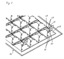
- the luminous field according to the invention consists essentially from a square inlaid in a suspended ceiling Frame 10, in its opening a square also Metal sheet grid 20 is inserted, and one on the frame 10th attached heat sink 40, at the bottom of several LEDs 50 are arranged like a grid.
- the frame 10 is in a known manner a bridge-like Mounting bracket 30 is provided for attachment to the ceiling.
- the grid according to the invention has a total of 16 grid-like arranged Single reflectors 22 on, each having the geometry have a truncated pyramid.
- the grid 20 consists of a sheet metal profile made of pre-anodised aluminum with square Floor space.
- the individual reflectors 22 are made of sheet metal profile truncated pyramidal reflector surfaces 24 punched out and bent up out of the plane of the grid 20.
- the Reflector surfaces 24 have at the oblique outer edges at a distance from each other two fastening tabs 26th on.
- On this mounting tabs 26 are used to form the complete individual reflectors 22 also truncated pyramidal Part reflectors 28 fitted, the corresponding openings for these fastening tabs 26 have.
- By bending over the fastening tabs 26 become the separate partial reflectors 28 on the grid 20 to form the individual reflectors 22 fixed.
- This "multi-piece" structure of the grid 20 allows the use of pre-anodized metal sheets for training arbitrary geometries of the individual reflectors, without the reflective surface damaged during deep drawing or the like becomes.
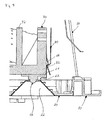
- the heat sink 40 is parallel at its top with several extending cooling fins 42 and provided on its underside provided with a planar mounting surface 44.
- On this mounting surface 44 are corresponding to the individual reflectors 22 of the grid 20 light-emitting diodes 50 with high wattage so at a distance from each other arranged that in the installed position in each case a light-emitting diode 50 projects into an upper opening 29 of the individual reflectors 22.
- each individual reflector 22 a associated with corresponding LED 50.
- the regular spaced from each other on the mounting surface 44 are also several LEDs on a connecting them Substrate can be arranged, which then attaches to the mounting surface 44 of the heat sink is attached.
- L-shaped grid plate 60 integrally formed in each case in the corners of the grid 20 are in the installed position outside partial reflectors 28 L-shaped grid plate 60 integrally formed.
- These grid tabs consist of a first from upper end of the partial reflector 28 is vertically upwards extending section, which then turns into a 90 degree bend an outwardly projecting horizontal section 62 passes and then after a further 90 degree bend up into one longer, second vertical section 64 merges, the its upper end has a locking projection 66.
- These resilient grid plate 60 engages in the installed position a corresponding trained grid plate 80 with a locking projection 82, to the grid 20 on the frame 10 and on the heat sink 40 to fix.
- an inventively designed luminous field can be realize the lighting of a room with 100 - 300 LUX luminosity.
- other grid divisions can also be used realize as the mentioned 4 X 4 screening.
- a sheet metal grid with a as Carriers for the LEDs serving heat sink can also existing lights with conventional bulbs on the operation be converted with LEDs. For this purpose must only those from the reflector, the heat sink and the LEDs existing unit are used in a luminaire.
- the metal sheet grid according to the invention is distinguished in comparison to the plastic barriers by a high heat resistance and good heat dissipation and thus supports the heat dissipation even with extreme temperature development of LEDs with high performance.
- the partial reflectors of the grid shield on the one hand the diodes off and on the other hand focus the light due to the high reflection effect of the material used.
Landscapes
- Engineering & Computer Science (AREA)
- General Engineering & Computer Science (AREA)
- Non-Portable Lighting Devices Or Systems Thereof (AREA)
- Arrangement Of Elements, Cooling, Sealing, Or The Like Of Lighting Devices (AREA)
- Medicines Containing Material From Animals Or Micro-Organisms (AREA)
- Fats And Perfumes (AREA)
- Detergent Compositions (AREA)
- Optical Elements Other Than Lenses (AREA)
Abstract
Description
- Fig. 1
- eine perspektivische Ansicht eines erfindungsgemäßen Leuchtenfeldes;
- Fig. 2
- eine Ansicht von unten des Leuchtenfeldes gemäß Figur 1;
- Fig. 3
- eine Ansicht des erfindungsgemäßen Rasters; und
- Fig. 4
- einen vergrößerten Ausschnitt entlang der Linie IV-IV gemäß Figur 2.
- 10
- Rahmen
- 20
- Raster
- 22
- Einzelreflektor
- 24
- Reflektorflächen
- 26
- Befestigungslasche
- 28
- Teilreflektoren
- 29
- Öffnung
- 30
- Montagebügel
- 40
- Kühlkörper
- 42
- Kühlrippe
- 44
- Montagefläche
- 50
- Leuchtdiode
- 60
- Rasterlasche
- 62
- Horizontalabschnitt
- 64
- zweiter Vertikalabschnitt
- 66
- Rastvorsprung
- 80
- Rastlasche
- 82
- Rastvorsprung
Claims (5)
- Leuchtenfeld, insbesondere für die Innenraumbeleuchtung, mit einer Mehrzahl von in einem bestimmten Abstand zueinander angeordneten Leuchtdioden (50), einem Tragelement (40), auf dem die Leuchtdioden (50) angeordnet sind und einem in Abstrahlrichtung vor den Leuchtdioden (50) angeordneten Reflektorkörper, der mehrere miteinander verbundene Einzelreflektoren (22) für die Leuchtdioden (50) aufweist, DADURCH GEKENNZEICHNET, dass der Reflektorkörper (20) als ein aus Metallblech bestehendes Raster (20) ausgebildet ist, dass das Metallblech hoch reflektierend ist und dass das Raster (20) mehrstückig ausgebildet ist.
- Leuchtenfeld nach Anspruch 1, DADURCH GEKENNZEICHNET, dass die Einzelreflektoren (22) als Pyramidenstümpfe ausgebildet sind.
- Leuchtenfeld nach einem der vorhergehenden Ansprüche, DADURCH GEKENNZEICHNET, dass an dem Raster (20) ein Teil eines Rasterverschlusses einstückig angeformt ist.
- Leuchtenfeld nach Anspruch 4, DADURCH GEKENNZEICHNET, dass der Teil eine an dem Raster angeformte Rastlasche (60) aufweist.
- Leuchtenfeld nach einem der vorhergehenden Ansprüche, DADURCH GEKENNZEICHNET, dass das Tragelement als Kühlkörper (40) ausgebildet ist.
Applications Claiming Priority (2)
| Application Number | Priority Date | Filing Date | Title |
|---|---|---|---|
| DE102004019137 | 2004-04-16 | ||
| DE102004019137A DE102004019137A1 (de) | 2004-04-16 | 2004-04-16 | Leuchtenfeld |
Publications (3)
| Publication Number | Publication Date |
|---|---|
| EP1586814A2 true EP1586814A2 (de) | 2005-10-19 |
| EP1586814A3 EP1586814A3 (de) | 2006-06-07 |
| EP1586814B1 EP1586814B1 (de) | 2010-12-01 |
Family
ID=34935133
Family Applications (1)
| Application Number | Title | Priority Date | Filing Date |
|---|---|---|---|
| EP05008107A Expired - Lifetime EP1586814B1 (de) | 2004-04-16 | 2005-04-13 | Leuchtenfeld |
Country Status (3)
| Country | Link |
|---|---|
| EP (1) | EP1586814B1 (de) |
| AT (1) | ATE490437T1 (de) |
| DE (2) | DE102004019137A1 (de) |
Cited By (22)
| Publication number | Priority date | Publication date | Assignee | Title |
|---|---|---|---|---|
| WO2008067447A1 (en) * | 2006-11-30 | 2008-06-05 | Cree Led Lighting Solutions, Inc. | Self-ballasted solid state lighting devices |
| WO2008098566A1 (de) * | 2007-02-14 | 2008-08-21 | Osram Opto Semiconductors Gmbh | Beleuchtungseinrichtung |
| WO2008137905A1 (en) * | 2007-05-07 | 2008-11-13 | Cree Led Lighting Solutions, Inc. | Light fixtures and lighting devices |
| WO2009068471A1 (en) * | 2007-11-26 | 2009-06-04 | Sergio Macchioni | Lighting device |
| US7625103B2 (en) | 2006-04-21 | 2009-12-01 | Cree, Inc. | Multiple thermal path packaging for solid state light emitting apparatus and associated assembling methods |
| US7648257B2 (en) | 2006-04-21 | 2010-01-19 | Cree, Inc. | Light emitting diode packages |
| EP2175194A1 (de) * | 2008-10-08 | 2010-04-14 | Delta Electronics, Inc. | Leuchtmittelvorrichtung und zugehörige Licht reflektierende Blende |
| EP2177818A1 (de) | 2008-10-17 | 2010-04-21 | BöSha Technische Produkte GmbH & Co. KG | Leuchteinheit einer Straßenlaterne |
| EP2180244A1 (de) * | 2008-10-27 | 2010-04-28 | Delta Electronics, Inc. | Lichtquellenvorrichtung und zugehörige Licht reflektierende Blende |
| EP2221522A1 (de) * | 2009-02-20 | 2010-08-25 | Te-Lung Chen | Modulstruktur der LED-Lichter und Heizkörper |
| EP2056016A4 (de) * | 2006-08-25 | 2010-09-29 | Furukawa Electric Co Ltd | Beleuchtungsvorrichtung |
| EP2320124A1 (de) * | 2009-11-10 | 2011-05-11 | LSI Industries, Inc. | Réflecteurs de lumière modulaires et ensembles pour luminaire |
| US8002428B2 (en) | 2007-10-17 | 2011-08-23 | Lsi Industries, Inc. | Luminaire and methods of use |
| EP2413024A2 (de) * | 2010-07-27 | 2012-02-01 | Panasonic Electric Works Co., Ltd. | Beleuchtungsvorrichtung |
| US8258682B2 (en) | 2007-02-12 | 2012-09-04 | Cree, Inc. | High thermal conductivity packaging for solid state light emitting apparatus and associated assembling methods |
| CN102840545A (zh) * | 2011-06-22 | 2012-12-26 | 海洋王照明科技股份有限公司 | 反光杯及泛光灯 |
| DE102011080313A1 (de) * | 2011-08-03 | 2013-02-07 | Osram Ag | Rasterleuchte mit mehreren halbleiterstrahlern |
| US8794787B2 (en) | 2009-11-10 | 2014-08-05 | Lsi Industries, Inc. | Modular light reflectors and assemblies for luminaire |
| WO2014173816A1 (de) * | 2013-04-25 | 2014-10-30 | Zumtobel Lighting Gmbh | Leuchte mit gehäuse mit mehreren lichtabstrahlöffnungen |
| US10976036B2 (en) | 2019-03-05 | 2021-04-13 | Abl Ip Holding Llc | Rotatable linear downlight |
| US12461412B2 (en) | 2022-06-01 | 2025-11-04 | Continental Automotive Technologies GmbH | Display apparatus and means of transportation |
| US12468083B2 (en) | 2022-06-01 | 2025-11-11 | Continental Automotive Technologies GmbH | Display apparatus and vehicle |
Families Citing this family (11)
| Publication number | Priority date | Publication date | Assignee | Title |
|---|---|---|---|---|
| DE102006056236B4 (de) * | 2006-11-27 | 2009-04-09 | Haschert, René | Gehäuse für Beleuchtungskörper sowie Leuchte, umfassend dieses Gehäuse, und deren Verwendung als Straßenlampe und Flutlichtvorrichtung |
| DE102009014526A1 (de) * | 2009-03-13 | 2010-09-16 | Lumitronix Led-Technik Gmbh | LED-Leuchtmittel |
| DE202009004252U1 (de) * | 2009-03-31 | 2010-05-27 | BÄRO GmbH & Co. KG | Leuchte |
| DE102009056904B4 (de) * | 2009-12-03 | 2012-04-26 | Kathrein-Austria Gmbh | LED-Leuchte |
| DE202009016793U1 (de) * | 2009-12-11 | 2011-04-21 | Zumtobel Lighting Gmbh | Anordnung zur Lichtabgabe |
| DE202011003418U1 (de) * | 2011-03-02 | 2012-06-04 | Ludwig Oberreuther | Leuchtenvorrichtung mit einer Halbleiterlichtquelle |
| DE202013001144U1 (de) | 2013-02-06 | 2013-03-20 | Esd Electronic Service & Design Gmbh | LED-Leuchtmittel |
| DE102013207609A1 (de) * | 2013-04-25 | 2014-10-30 | Osram Gmbh | Reflektoranordnung mit mehreren Reflektoren und Halbleiterlichtquellen |
| DE202013101791U1 (de) * | 2013-04-25 | 2014-07-28 | Zumtobel Lighting Gmbh | Abdeckungselement für Flächenleuchte |
| DE202013101816U1 (de) * | 2013-04-26 | 2014-07-29 | Zumtobel Lighting Gmbh | Optisches Element für eine LED-Lichtquelle, Anordnung zur Lichtabgabe sowie Leuchte |
| USD979826S1 (en) | 2020-02-25 | 2023-02-28 | Abl Ip Holding Llc | Luminaire |
Citations (2)
| Publication number | Priority date | Publication date | Assignee | Title |
|---|---|---|---|---|
| WO1999041785A1 (de) | 1998-02-12 | 1999-08-19 | Gerhard Staufert | Konfektionierbares led-leuchtpaneel |
| DE20116022U1 (de) | 2001-04-09 | 2002-01-24 | Bartenbach, Christian, Aldrans, Tirol | Leuchtenfeld zur Beleuchtung von Räumen mit einer Vielzahl von LEDs |
Family Cites Families (9)
| Publication number | Priority date | Publication date | Assignee | Title |
|---|---|---|---|---|
| DE3148843C2 (de) * | 1981-12-10 | 1986-01-02 | Telefunken electronic GmbH, 7100 Heilbronn | Mehrfach-Leuchtdiodenanordnung |
| DE3803951A1 (de) * | 1988-02-10 | 1989-08-24 | Mentor Gmbh & Co | Reflektor-leuchte |
| US5390092A (en) * | 1994-06-01 | 1995-02-14 | Formosa Industrial Computing Inc. | Receptacle apparatus for light emitting diodes |
| US5660461A (en) * | 1994-12-08 | 1997-08-26 | Quantum Devices, Inc. | Arrays of optoelectronic devices and method of making same |
| DE29505546U1 (de) * | 1995-04-02 | 1995-09-28 | Bruckner, Attila A., Dipl.-Ing., 65582 Hambach | Einteiliger Lichtlenkvorsatz für freistrahlende Miniaturreflektoren |
| US5806972A (en) * | 1996-10-21 | 1998-09-15 | National Service Industries, Inc. | Light trap and louver mounting to fluorescent troffer lighting fixture |
| US6106137A (en) * | 1998-02-20 | 2000-08-22 | Lorin Industries, Inc. | Reflector for automotive exterior lighting |
| EP1451872B1 (de) * | 2001-09-13 | 2007-03-07 | Lucea AG | Leuchtdioden-leuchtpaneel und leiterplatte |
| WO2003088195A1 (en) * | 2002-04-17 | 2003-10-23 | Kabushiki Kaisha Box | Surface light emitting device |
-
2004
- 2004-04-16 DE DE102004019137A patent/DE102004019137A1/de not_active Withdrawn
-
2005
- 2005-04-13 DE DE502005010602T patent/DE502005010602D1/de not_active Expired - Lifetime
- 2005-04-13 EP EP05008107A patent/EP1586814B1/de not_active Expired - Lifetime
- 2005-04-13 AT AT05008107T patent/ATE490437T1/de active
Patent Citations (2)
| Publication number | Priority date | Publication date | Assignee | Title |
|---|---|---|---|---|
| WO1999041785A1 (de) | 1998-02-12 | 1999-08-19 | Gerhard Staufert | Konfektionierbares led-leuchtpaneel |
| DE20116022U1 (de) | 2001-04-09 | 2002-01-24 | Bartenbach, Christian, Aldrans, Tirol | Leuchtenfeld zur Beleuchtung von Räumen mit einer Vielzahl von LEDs |
Cited By (35)
| Publication number | Priority date | Publication date | Assignee | Title |
|---|---|---|---|---|
| US7625103B2 (en) | 2006-04-21 | 2009-12-01 | Cree, Inc. | Multiple thermal path packaging for solid state light emitting apparatus and associated assembling methods |
| US7648257B2 (en) | 2006-04-21 | 2010-01-19 | Cree, Inc. | Light emitting diode packages |
| EP2056016A4 (de) * | 2006-08-25 | 2010-09-29 | Furukawa Electric Co Ltd | Beleuchtungsvorrichtung |
| WO2008067447A1 (en) * | 2006-11-30 | 2008-06-05 | Cree Led Lighting Solutions, Inc. | Self-ballasted solid state lighting devices |
| US8057070B2 (en) | 2006-11-30 | 2011-11-15 | Cree, Inc. | Self-ballasted solid state lighting devices |
| TWI426200B (zh) * | 2006-11-30 | 2014-02-11 | Cree Inc | 自鎮流固態照明裝置 |
| US8258682B2 (en) | 2007-02-12 | 2012-09-04 | Cree, Inc. | High thermal conductivity packaging for solid state light emitting apparatus and associated assembling methods |
| US9070311B2 (en) | 2007-02-14 | 2015-06-30 | Osram Opto Semiconductors Gmbh | Illumination device with radiation reflectors arranged modularly to form a radiation-reflecting luminous area |
| WO2008098566A1 (de) * | 2007-02-14 | 2008-08-21 | Osram Opto Semiconductors Gmbh | Beleuchtungseinrichtung |
| CN101790660B (zh) * | 2007-05-07 | 2013-10-09 | 科锐公司 | 灯具及照明装置 |
| US8789975B2 (en) | 2007-05-07 | 2014-07-29 | Cree, Inc. | Light fixtures and lighting devices |
| WO2008137905A1 (en) * | 2007-05-07 | 2008-11-13 | Cree Led Lighting Solutions, Inc. | Light fixtures and lighting devices |
| US8136965B2 (en) | 2007-05-07 | 2012-03-20 | Cree, Inc. | Light fixtures and lighting devices |
| US8177386B2 (en) | 2007-10-17 | 2012-05-15 | Lsi Industries, Inc. | Luminaire and methods of use |
| US9194550B2 (en) | 2007-10-17 | 2015-11-24 | Lsi Industries, Inc. | Roadway luminaire and methods of use |
| US8434893B2 (en) | 2007-10-17 | 2013-05-07 | Lsi Industries, Inc. | Luminaire and methods of use |
| US8002428B2 (en) | 2007-10-17 | 2011-08-23 | Lsi Industries, Inc. | Luminaire and methods of use |
| US8567983B2 (en) | 2007-10-17 | 2013-10-29 | Lsi Industries, Inc. | Roadway luminaire and methods of use |
| WO2009068471A1 (en) * | 2007-11-26 | 2009-06-04 | Sergio Macchioni | Lighting device |
| EP2175194A1 (de) * | 2008-10-08 | 2010-04-14 | Delta Electronics, Inc. | Leuchtmittelvorrichtung und zugehörige Licht reflektierende Blende |
| EP2177818A1 (de) | 2008-10-17 | 2010-04-21 | BöSha Technische Produkte GmbH & Co. KG | Leuchteinheit einer Straßenlaterne |
| EP2180244A1 (de) * | 2008-10-27 | 2010-04-28 | Delta Electronics, Inc. | Lichtquellenvorrichtung und zugehörige Licht reflektierende Blende |
| EP2221522A1 (de) * | 2009-02-20 | 2010-08-25 | Te-Lung Chen | Modulstruktur der LED-Lichter und Heizkörper |
| US8794787B2 (en) | 2009-11-10 | 2014-08-05 | Lsi Industries, Inc. | Modular light reflectors and assemblies for luminaire |
| US8042968B2 (en) | 2009-11-10 | 2011-10-25 | Lsi Industries, Inc. | Modular light reflectors and assemblies for luminaire |
| JP2011103288A (ja) * | 2009-11-10 | 2011-05-26 | Lsi Industries Inc | 照明器具用モジュール式光リフレクタ及びアッセンブリ |
| EP2320124A1 (de) * | 2009-11-10 | 2011-05-11 | LSI Industries, Inc. | Réflecteurs de lumière modulaires et ensembles pour luminaire |
| EP2413024A2 (de) * | 2010-07-27 | 2012-02-01 | Panasonic Electric Works Co., Ltd. | Beleuchtungsvorrichtung |
| CN102840545B (zh) * | 2011-06-22 | 2014-01-22 | 海洋王照明科技股份有限公司 | 反光杯及泛光灯 |
| CN102840545A (zh) * | 2011-06-22 | 2012-12-26 | 海洋王照明科技股份有限公司 | 反光杯及泛光灯 |
| DE102011080313A1 (de) * | 2011-08-03 | 2013-02-07 | Osram Ag | Rasterleuchte mit mehreren halbleiterstrahlern |
| WO2014173816A1 (de) * | 2013-04-25 | 2014-10-30 | Zumtobel Lighting Gmbh | Leuchte mit gehäuse mit mehreren lichtabstrahlöffnungen |
| US10976036B2 (en) | 2019-03-05 | 2021-04-13 | Abl Ip Holding Llc | Rotatable linear downlight |
| US12461412B2 (en) | 2022-06-01 | 2025-11-04 | Continental Automotive Technologies GmbH | Display apparatus and means of transportation |
| US12468083B2 (en) | 2022-06-01 | 2025-11-11 | Continental Automotive Technologies GmbH | Display apparatus and vehicle |
Also Published As
| Publication number | Publication date |
|---|---|
| EP1586814B1 (de) | 2010-12-01 |
| DE102004019137A1 (de) | 2005-11-17 |
| DE502005010602D1 (de) | 2011-01-13 |
| ATE490437T1 (de) | 2010-12-15 |
| EP1586814A3 (de) | 2006-06-07 |
Similar Documents
| Publication | Publication Date | Title |
|---|---|---|
| EP1586814B1 (de) | Leuchtenfeld | |
| EP1154200B1 (de) | Lichtverteiler für eine Leuchteinrichtung sowie Leuchteinrichtung und Verwendung einer Leuchteinrichtung | |
| EP2411728B1 (de) | Träger mit mindestens einer halbleiterleuchtvorrichtung und trägersystem | |
| DE102008052869B4 (de) | Leuchte mit LED-Tragschiene | |
| EP1043542B2 (de) | Beleuchtungsanordnung zur Anbringung an der Decke oder einer Wand eines Raumes | |
| EP2491295B1 (de) | Linienlampe | |
| DE202009017522U1 (de) | LED-Einbauleuchte mit Kühlkörper | |
| DE202010001126U1 (de) | LED-Leuchtvorrichtung zur Erhöhung der Beleuchtungsstärke | |
| DE102011051038A1 (de) | LED Beleuchtungsanordnung | |
| CH709009A1 (de) | Befestigung einer Leiterplatte und einer Optik einer Leuchte. | |
| DE102010062454A1 (de) | Anordnung zur Lichtabgabe | |
| WO2011000554A1 (de) | Led leuchtmittel und led flachleuchte | |
| EP2273185B1 (de) | LED-Leuchteneinsatz mit Lichtlenkelement | |
| DE202011108542U1 (de) | Leuchte, insbesondere Wand- und/oder Deckenleuchte | |
| DE102012102973A1 (de) | Leuchte mit integriertem Kühlkörper | |
| DE102010015210A1 (de) | Leuchte | |
| DE102008003703A1 (de) | Leuchte mit einem Leuchtengehäuse in Form eines Hohlprofils | |
| DE102013108248A1 (de) | Beleuchtungssystem, insbesondere für einen Kraftfahrzeugscheinwerfer mit einem Kühlkörper | |
| DE202009017585U1 (de) | LED-Einbauleuchte mit Reflexionsplatte | |
| AT509626B1 (de) | Modulares led beleuchtungssystem mit partieller lichtstärkenanpassung | |
| EP2244003A1 (de) | Strassenleuchte | |
| DE102016104221A1 (de) | LED-Leuchte mit Lichtlenkelement | |
| DE202010005507U1 (de) | LED-Beleuchtungseinrichtung | |
| DE202007013177U1 (de) | Leuchte | |
| DE102011001113B4 (de) | Leuchte |
Legal Events
| Date | Code | Title | Description |
|---|---|---|---|
| PUAI | Public reference made under article 153(3) epc to a published international application that has entered the european phase |
Free format text: ORIGINAL CODE: 0009012 |
|
| AK | Designated contracting states |
Kind code of ref document: A2 Designated state(s): AT BE BG CH CY CZ DE DK EE ES FI FR GB GR HU IE IS IT LI LT LU MC NL PL PT RO SE SI SK TR |
|
| AX | Request for extension of the european patent |
Extension state: AL BA HR LV MK YU |
|
| PUAL | Search report despatched |
Free format text: ORIGINAL CODE: 0009013 |
|
| AK | Designated contracting states |
Kind code of ref document: A3 Designated state(s): AT BE BG CH CY CZ DE DK EE ES FI FR GB GR HU IE IS IT LI LT LU MC NL PL PT RO SE SI SK TR |
|
| AX | Request for extension of the european patent |
Extension state: AL BA HR LV MK YU |
|
| 17P | Request for examination filed |
Effective date: 20060913 |
|
| AKX | Designation fees paid |
Designated state(s): AT BE BG CH CY CZ DE DK EE ES FI FR GB GR HU IE IS IT LI LT LU MC NL PL PT RO SE SI SK TR |
|
| 17Q | First examination report despatched |
Effective date: 20070523 |
|
| RAP1 | Party data changed (applicant data changed or rights of an application transferred) |
Owner name: TRILUX GMBH & CO.KG |
|
| GRAP | Despatch of communication of intention to grant a patent |
Free format text: ORIGINAL CODE: EPIDOSNIGR1 |
|
| GRAS | Grant fee paid |
Free format text: ORIGINAL CODE: EPIDOSNIGR3 |
|
| GRAA | (expected) grant |
Free format text: ORIGINAL CODE: 0009210 |
|
| AK | Designated contracting states |
Kind code of ref document: B1 Designated state(s): AT BE BG CH CY CZ DE DK EE ES FI FR GB GR HU IE IS IT LI LT LU MC NL PL PT RO SE SI SK TR |
|
| REG | Reference to a national code |
Ref country code: GB Ref legal event code: FG4D Free format text: NOT ENGLISH |
|
| REG | Reference to a national code |
Ref country code: CH Ref legal event code: EP |
|
| REG | Reference to a national code |
Ref country code: IE Ref legal event code: FG4D |
|
| REF | Corresponds to: |
Ref document number: 502005010602 Country of ref document: DE Date of ref document: 20110113 Kind code of ref document: P |
|
| REG | Reference to a national code |
Ref country code: NL Ref legal event code: T3 |
|
| PG25 | Lapsed in a contracting state [announced via postgrant information from national office to epo] |
Ref country code: LT Free format text: LAPSE BECAUSE OF FAILURE TO SUBMIT A TRANSLATION OF THE DESCRIPTION OR TO PAY THE FEE WITHIN THE PRESCRIBED TIME-LIMIT Effective date: 20101201 |
|
| LTIE | Lt: invalidation of european patent or patent extension |
Effective date: 20101201 |
|
| PG25 | Lapsed in a contracting state [announced via postgrant information from national office to epo] |
Ref country code: SE Free format text: LAPSE BECAUSE OF FAILURE TO SUBMIT A TRANSLATION OF THE DESCRIPTION OR TO PAY THE FEE WITHIN THE PRESCRIBED TIME-LIMIT Effective date: 20101201 Ref country code: FI Free format text: LAPSE BECAUSE OF FAILURE TO SUBMIT A TRANSLATION OF THE DESCRIPTION OR TO PAY THE FEE WITHIN THE PRESCRIBED TIME-LIMIT Effective date: 20101201 Ref country code: SI Free format text: LAPSE BECAUSE OF FAILURE TO SUBMIT A TRANSLATION OF THE DESCRIPTION OR TO PAY THE FEE WITHIN THE PRESCRIBED TIME-LIMIT Effective date: 20101201 Ref country code: CY Free format text: LAPSE BECAUSE OF FAILURE TO SUBMIT A TRANSLATION OF THE DESCRIPTION OR TO PAY THE FEE WITHIN THE PRESCRIBED TIME-LIMIT Effective date: 20101201 Ref country code: BG Free format text: LAPSE BECAUSE OF FAILURE TO SUBMIT A TRANSLATION OF THE DESCRIPTION OR TO PAY THE FEE WITHIN THE PRESCRIBED TIME-LIMIT Effective date: 20110301 |
|
| REG | Reference to a national code |
Ref country code: IE Ref legal event code: FD4D |
|
| PG25 | Lapsed in a contracting state [announced via postgrant information from national office to epo] |
Ref country code: GR Free format text: LAPSE BECAUSE OF FAILURE TO SUBMIT A TRANSLATION OF THE DESCRIPTION OR TO PAY THE FEE WITHIN THE PRESCRIBED TIME-LIMIT Effective date: 20110302 |
|
| PG25 | Lapsed in a contracting state [announced via postgrant information from national office to epo] |
Ref country code: EE Free format text: LAPSE BECAUSE OF FAILURE TO SUBMIT A TRANSLATION OF THE DESCRIPTION OR TO PAY THE FEE WITHIN THE PRESCRIBED TIME-LIMIT Effective date: 20101201 Ref country code: IS Free format text: LAPSE BECAUSE OF FAILURE TO SUBMIT A TRANSLATION OF THE DESCRIPTION OR TO PAY THE FEE WITHIN THE PRESCRIBED TIME-LIMIT Effective date: 20110401 Ref country code: PT Free format text: LAPSE BECAUSE OF FAILURE TO SUBMIT A TRANSLATION OF THE DESCRIPTION OR TO PAY THE FEE WITHIN THE PRESCRIBED TIME-LIMIT Effective date: 20110401 Ref country code: CZ Free format text: LAPSE BECAUSE OF FAILURE TO SUBMIT A TRANSLATION OF THE DESCRIPTION OR TO PAY THE FEE WITHIN THE PRESCRIBED TIME-LIMIT Effective date: 20101201 Ref country code: IE Free format text: LAPSE BECAUSE OF FAILURE TO SUBMIT A TRANSLATION OF THE DESCRIPTION OR TO PAY THE FEE WITHIN THE PRESCRIBED TIME-LIMIT Effective date: 20101201 Ref country code: ES Free format text: LAPSE BECAUSE OF FAILURE TO SUBMIT A TRANSLATION OF THE DESCRIPTION OR TO PAY THE FEE WITHIN THE PRESCRIBED TIME-LIMIT Effective date: 20110312 |
|
| PG25 | Lapsed in a contracting state [announced via postgrant information from national office to epo] |
Ref country code: RO Free format text: LAPSE BECAUSE OF FAILURE TO SUBMIT A TRANSLATION OF THE DESCRIPTION OR TO PAY THE FEE WITHIN THE PRESCRIBED TIME-LIMIT Effective date: 20101201 Ref country code: SK Free format text: LAPSE BECAUSE OF FAILURE TO SUBMIT A TRANSLATION OF THE DESCRIPTION OR TO PAY THE FEE WITHIN THE PRESCRIBED TIME-LIMIT Effective date: 20101201 Ref country code: PL Free format text: LAPSE BECAUSE OF FAILURE TO SUBMIT A TRANSLATION OF THE DESCRIPTION OR TO PAY THE FEE WITHIN THE PRESCRIBED TIME-LIMIT Effective date: 20101201 |
|
| PLBE | No opposition filed within time limit |
Free format text: ORIGINAL CODE: 0009261 |
|
| STAA | Information on the status of an ep patent application or granted ep patent |
Free format text: STATUS: NO OPPOSITION FILED WITHIN TIME LIMIT |
|
| PG25 | Lapsed in a contracting state [announced via postgrant information from national office to epo] |
Ref country code: DK Free format text: LAPSE BECAUSE OF FAILURE TO SUBMIT A TRANSLATION OF THE DESCRIPTION OR TO PAY THE FEE WITHIN THE PRESCRIBED TIME-LIMIT Effective date: 20101201 |
|
| 26N | No opposition filed |
Effective date: 20110902 |
|
| PG25 | Lapsed in a contracting state [announced via postgrant information from national office to epo] |
Ref country code: MC Free format text: LAPSE BECAUSE OF NON-PAYMENT OF DUE FEES Effective date: 20110430 |
|
| REG | Reference to a national code |
Ref country code: CH Ref legal event code: PL |
|
| REG | Reference to a national code |
Ref country code: DE Ref legal event code: R097 Ref document number: 502005010602 Country of ref document: DE Effective date: 20110902 |
|
| REG | Reference to a national code |
Ref country code: FR Ref legal event code: ST Effective date: 20111230 |
|
| PG25 | Lapsed in a contracting state [announced via postgrant information from national office to epo] |
Ref country code: FR Free format text: LAPSE BECAUSE OF NON-PAYMENT OF DUE FEES Effective date: 20110502 Ref country code: LI Free format text: LAPSE BECAUSE OF NON-PAYMENT OF DUE FEES Effective date: 20110430 Ref country code: CH Free format text: LAPSE BECAUSE OF NON-PAYMENT OF DUE FEES Effective date: 20110430 |
|
| PG25 | Lapsed in a contracting state [announced via postgrant information from national office to epo] |
Ref country code: LU Free format text: LAPSE BECAUSE OF NON-PAYMENT OF DUE FEES Effective date: 20110413 |
|
| PG25 | Lapsed in a contracting state [announced via postgrant information from national office to epo] |
Ref country code: TR Free format text: LAPSE BECAUSE OF FAILURE TO SUBMIT A TRANSLATION OF THE DESCRIPTION OR TO PAY THE FEE WITHIN THE PRESCRIBED TIME-LIMIT Effective date: 20101201 |
|
| PG25 | Lapsed in a contracting state [announced via postgrant information from national office to epo] |
Ref country code: HU Free format text: LAPSE BECAUSE OF FAILURE TO SUBMIT A TRANSLATION OF THE DESCRIPTION OR TO PAY THE FEE WITHIN THE PRESCRIBED TIME-LIMIT Effective date: 20101201 |
|
| PGFP | Annual fee paid to national office [announced via postgrant information from national office to epo] |
Ref country code: NL Payment date: 20180423 Year of fee payment: 14 |
|
| PGFP | Annual fee paid to national office [announced via postgrant information from national office to epo] |
Ref country code: FR Payment date: 20180822 Year of fee payment: 5 Ref country code: BE Payment date: 20180423 Year of fee payment: 14 |
|
| REG | Reference to a national code |
Ref country code: NL Ref legal event code: MM Effective date: 20190501 |
|
| REG | Reference to a national code |
Ref country code: BE Ref legal event code: MM Effective date: 20190430 |
|
| PG25 | Lapsed in a contracting state [announced via postgrant information from national office to epo] |
Ref country code: NL Free format text: LAPSE BECAUSE OF NON-PAYMENT OF DUE FEES Effective date: 20190501 |
|
| PG25 | Lapsed in a contracting state [announced via postgrant information from national office to epo] |
Ref country code: BE Free format text: LAPSE BECAUSE OF NON-PAYMENT OF DUE FEES Effective date: 20190430 |
|
| PG25 | Lapsed in a contracting state [announced via postgrant information from national office to epo] |
Ref country code: IT Free format text: LAPSE BECAUSE OF NON-PAYMENT OF DUE FEES Effective date: 20190413 |
|
| PGFP | Annual fee paid to national office [announced via postgrant information from national office to epo] |
Ref country code: DE Payment date: 20200625 Year of fee payment: 16 |
|
| PGFP | Annual fee paid to national office [announced via postgrant information from national office to epo] |
Ref country code: GB Payment date: 20200423 Year of fee payment: 16 |
|
| PGFP | Annual fee paid to national office [announced via postgrant information from national office to epo] |
Ref country code: AT Payment date: 20200421 Year of fee payment: 16 |
|
| REG | Reference to a national code |
Ref country code: DE Ref legal event code: R119 Ref document number: 502005010602 Country of ref document: DE |
|
| REG | Reference to a national code |
Ref country code: AT Ref legal event code: MM01 Ref document number: 490437 Country of ref document: AT Kind code of ref document: T Effective date: 20210413 |
|
| GBPC | Gb: european patent ceased through non-payment of renewal fee |
Effective date: 20210413 |
|
| PG25 | Lapsed in a contracting state [announced via postgrant information from national office to epo] |
Ref country code: AT Free format text: LAPSE BECAUSE OF NON-PAYMENT OF DUE FEES Effective date: 20210413 Ref country code: GB Free format text: LAPSE BECAUSE OF NON-PAYMENT OF DUE FEES Effective date: 20210413 Ref country code: DE Free format text: LAPSE BECAUSE OF NON-PAYMENT OF DUE FEES Effective date: 20211103 |