EP1586824A2 - Armoire de climatisation, humidificateur et méthode de climatisation d'une pièce - Google Patents
Armoire de climatisation, humidificateur et méthode de climatisation d'une pièce Download PDFInfo
- Publication number
- EP1586824A2 EP1586824A2 EP05008102A EP05008102A EP1586824A2 EP 1586824 A2 EP1586824 A2 EP 1586824A2 EP 05008102 A EP05008102 A EP 05008102A EP 05008102 A EP05008102 A EP 05008102A EP 1586824 A2 EP1586824 A2 EP 1586824A2
- Authority
- EP
- European Patent Office
- Prior art keywords
- moisture
- air
- climatic
- cabinet according
- interior
- Prior art date
- Legal status (The legal status is an assumption and is not a legal conclusion. Google has not performed a legal analysis and makes no representation as to the accuracy of the status listed.)
- Withdrawn
Links
- 238000000034 method Methods 0.000 title claims description 13
- 238000001816 cooling Methods 0.000 claims abstract description 19
- 239000007788 liquid Substances 0.000 claims abstract description 13
- 238000010438 heat treatment Methods 0.000 claims description 16
- 238000004378 air conditioning Methods 0.000 claims description 10
- 238000007791 dehumidification Methods 0.000 claims description 5
- 239000002244 precipitate Substances 0.000 claims description 4
- 239000011521 glass Substances 0.000 claims description 3
- 230000005855 radiation Effects 0.000 claims description 3
- 230000003750 conditioning effect Effects 0.000 claims description 2
- 238000005057 refrigeration Methods 0.000 claims description 2
- 238000011144 upstream manufacturing Methods 0.000 claims description 2
- 230000015572 biosynthetic process Effects 0.000 claims 2
- XLYOFNOQVPJJNP-UHFFFAOYSA-N water Substances O XLYOFNOQVPJJNP-UHFFFAOYSA-N 0.000 abstract description 7
- 238000007664 blowing Methods 0.000 abstract 1
- 235000019506 cigar Nutrition 0.000 description 8
- 238000009833 condensation Methods 0.000 description 5
- 230000005494 condensation Effects 0.000 description 5
- 238000001704 evaporation Methods 0.000 description 4
- 230000008020 evaporation Effects 0.000 description 4
- 239000002023 wood Substances 0.000 description 4
- DNIAPMSPPWPWGF-UHFFFAOYSA-N Propylene glycol Chemical compound CC(O)CO DNIAPMSPPWPWGF-UHFFFAOYSA-N 0.000 description 3
- 239000000126 substance Substances 0.000 description 3
- 235000014101 wine Nutrition 0.000 description 3
- 241000218645 Cedrus Species 0.000 description 2
- 239000004927 clay Substances 0.000 description 2
- 239000012530 fluid Substances 0.000 description 2
- 238000009413 insulation Methods 0.000 description 2
- 239000000463 material Substances 0.000 description 2
- 229920000058 polyacrylate Polymers 0.000 description 2
- 238000004659 sterilization and disinfection Methods 0.000 description 2
- OKTJSMMVPCPJKN-UHFFFAOYSA-N Carbon Chemical compound [C] OKTJSMMVPCPJKN-UHFFFAOYSA-N 0.000 description 1
- 230000000844 anti-bacterial effect Effects 0.000 description 1
- 229910052799 carbon Inorganic materials 0.000 description 1
- 230000003247 decreasing effect Effects 0.000 description 1
- 230000003670 easy-to-clean Effects 0.000 description 1
- 235000021022 fresh fruits Nutrition 0.000 description 1
- 238000003197 gene knockdown Methods 0.000 description 1
- 239000008187 granular material Substances 0.000 description 1
- 229910052602 gypsum Inorganic materials 0.000 description 1
- 239000010440 gypsum Substances 0.000 description 1
- 230000002401 inhibitory effect Effects 0.000 description 1
- 238000004519 manufacturing process Methods 0.000 description 1
- 230000035515 penetration Effects 0.000 description 1
- 238000001556 precipitation Methods 0.000 description 1
- 239000011435 rock Substances 0.000 description 1
- 230000000087 stabilizing effect Effects 0.000 description 1
- 239000011232 storage material Substances 0.000 description 1
- 238000013517 stratification Methods 0.000 description 1
- 238000009281 ultraviolet germicidal irradiation Methods 0.000 description 1
- 235000013311 vegetables Nutrition 0.000 description 1
- 238000010792 warming Methods 0.000 description 1
Images

Classifications
-
- F—MECHANICAL ENGINEERING; LIGHTING; HEATING; WEAPONS; BLASTING
- F25—REFRIGERATION OR COOLING; COMBINED HEATING AND REFRIGERATION SYSTEMS; HEAT PUMP SYSTEMS; MANUFACTURE OR STORAGE OF ICE; LIQUEFACTION SOLIDIFICATION OF GASES
- F25D—REFRIGERATORS; COLD ROOMS; ICE-BOXES; COOLING OR FREEZING APPARATUS NOT OTHERWISE PROVIDED FOR
- F25D17/00—Arrangements for circulating cooling fluids; Arrangements for circulating gas, e.g. air, within refrigerated spaces
- F25D17/04—Arrangements for circulating cooling fluids; Arrangements for circulating gas, e.g. air, within refrigerated spaces for circulating air, e.g. by convection
- F25D17/042—Air treating means within refrigerated spaces
-
- A—HUMAN NECESSITIES
- A47—FURNITURE; DOMESTIC ARTICLES OR APPLIANCES; COFFEE MILLS; SPICE MILLS; SUCTION CLEANERS IN GENERAL
- A47F—SPECIAL FURNITURE, FITTINGS, OR ACCESSORIES FOR SHOPS, STOREHOUSES, BARS, RESTAURANTS OR THE LIKE; PAYING COUNTERS
- A47F3/00—Show cases or show cabinets
- A47F3/001—Devices for lighting, humidifying, heating, ventilation
-
- F—MECHANICAL ENGINEERING; LIGHTING; HEATING; WEAPONS; BLASTING
- F25—REFRIGERATION OR COOLING; COMBINED HEATING AND REFRIGERATION SYSTEMS; HEAT PUMP SYSTEMS; MANUFACTURE OR STORAGE OF ICE; LIQUEFACTION SOLIDIFICATION OF GASES
- F25B—REFRIGERATION MACHINES, PLANTS OR SYSTEMS; COMBINED HEATING AND REFRIGERATION SYSTEMS; HEAT PUMP SYSTEMS
- F25B2600/00—Control issues
- F25B2600/11—Fan speed control
- F25B2600/112—Fan speed control of evaporator fans
-
- F—MECHANICAL ENGINEERING; LIGHTING; HEATING; WEAPONS; BLASTING
- F25—REFRIGERATION OR COOLING; COMBINED HEATING AND REFRIGERATION SYSTEMS; HEAT PUMP SYSTEMS; MANUFACTURE OR STORAGE OF ICE; LIQUEFACTION SOLIDIFICATION OF GASES
- F25B—REFRIGERATION MACHINES, PLANTS OR SYSTEMS; COMBINED HEATING AND REFRIGERATION SYSTEMS; HEAT PUMP SYSTEMS
- F25B2700/00—Sensing or detecting of parameters; Sensors therefor
- F25B2700/02—Humidity
-
- F—MECHANICAL ENGINEERING; LIGHTING; HEATING; WEAPONS; BLASTING
- F25—REFRIGERATION OR COOLING; COMBINED HEATING AND REFRIGERATION SYSTEMS; HEAT PUMP SYSTEMS; MANUFACTURE OR STORAGE OF ICE; LIQUEFACTION SOLIDIFICATION OF GASES
- F25D—REFRIGERATORS; COLD ROOMS; ICE-BOXES; COOLING OR FREEZING APPARATUS NOT OTHERWISE PROVIDED FOR
- F25D2317/00—Details or arrangements for circulating cooling fluids; Details or arrangements for circulating gas, e.g. air, within refrigerated spaces, not provided for in other groups of this subclass
- F25D2317/04—Treating air flowing to refrigeration compartments
- F25D2317/041—Treating air flowing to refrigeration compartments by purification
- F25D2317/0411—Treating air flowing to refrigeration compartments by purification by dehumidification
Definitions
- the invention relates to a climatic cabinet with a heat-insulating housing, a humidor that includes such a climate chamber, and a method for Air conditioning a climate chamber, in particular the interior of a climate cabinet.
- DE 101 64 321 C1 describes a device for conditioning a climate cabinet, with the help of a blower air through a moisture container is guided and over an arrangement of outlets, which over the climatic cabinet are distributed in these for indoor humidification is introduced.
- Object of the present invention is a climate chamber, a humidor and to provide a method for air conditioning a climatic room, with the aid of which in particular, without generating excessive air currents, a constant temperature and humidity can be adjusted and safely maintained.
- the climate chamber according to the invention has a heat-insulating housing, a Cooling device and a moisture container.
- a first blower serves as Air humidification fan for transporting air to be humidified.
- a second Blower is used to transport air to and from the cooling device and / or for the circulation of air in the climatic cabinet.
- the second blower serves for Air circulation in the climate chamber and / or leads the air past the cooling device, so that a constant internal temperature with minimal temperature stratification can be achieved.
- the inventive Carry out a process for the air conditioning of a climatic room.
- the method according to the invention becomes the first during the humidifying operation Blower put into service to indoor air at a moisture surface to pass and moisten in this way.
- the air in the interior of the climate-controlled air-conditioning room with the help of a second blower passed a cooling device over. Both are for dehumidification Blower off, so that the moisture precipitate on the cooling device and drain.
- the cooling device of the climate chamber may be, for. B. to maintain a manner known per se in refrigerators a desired temperature controlled evaporator act.
- the evaporator is preferably arranged on the rear wall of the climatic chamber, so that he as far away as possible from the door opening.
- the first fan serving as Heilbefeuchtungsgebläse a Create air flow over the surface of the moisture container, so that this Air can absorb moisture and humidity increases.
- the moisture container two tight at rest having closing flaps. These flaps are arranged so that at Generating an air flow with the help of the first blower both flaps in the air flow are located and open, with one flap upstream and the other Flap located downstream of the moisture surface.
- the Damper control in the humidification unit ensures that when unfavorable Operating conditions no additional moisture in the interior reflected.
- the flaps are closed and the Moisture container thus sealed, so that a humidification not taking place.
- the moisture container with the two flaps and the first blower is a modular unit, the total in the climatic cabinet used and removed as a whole.
- Such Module unit is easy to fill and easy to clean.
- the moisture container becomes automatic filled via a Festigananschluß or from a storage tank, the z. B. with UV light can be irradiated to produce an antibacterial effect.
- the inventive climate chamber include a moisture sensor, the z. B. through mediation a microprocessor can be used to control the blower. at In another embodiment, the moisture sensor z. B. for production and dispensing a warning signal when the humidity is a leaves the predetermined desired area.
- Both the first and the second blower can be speed-controlled.
- the Control is z. B. in response to the signals from a humidity sensor or a temperature sensor z. B. via a corresponding microprocessor circuit performed.
- Such a speed control of either the first or the second blower or both blowers allows even more precise control the climate parameters in the climate chamber.
- the climate cabinet comprises a Control that turns off the first fan when the humidity in the interior climatic cabinet exceeds a first predetermined limit.
- This Limit can z. B. taking into account the moisture compatibility of the be determined good.
- the z. B. correspond to the first limit can, even the second fan is turned off. This way will the air circulation is interrupted and the dehumidification is further supported.
- the damp Air can now precipitate on the cooling device without being affected by the first blower is transported away. Which precipitates at the cooling device Air can drip off and z. B. discharged through a condensation drainage channel become.
- a moisture container heating element may be provided, preferably under the moisture container is arranged. During the humidification operation causes the operation of this heating element, a stronger evaporation of the Liquid surface and thus a stronger humidification above the Fluid surface moving air.
- the moisture container heating element may also be part of the humidification module.
- the moisture container heating element can also be mounted freely or z. B. in the Heat insulation of the climate chamber be foamed.
- a development of the climate chamber according to the invention has an interior heating element on. At low ambient temperature, this interior heating is used to maintain the desired constant internal temperature.
- the Interior heating element can also be used for dehumidification become. With appropriate control of the interior heating, the increase the temperature cause a light-off of the cooling device, so that this one Increased cooling mode absorbs and moisture from the air at the cooling device effectively knock down.
- the climate chamber according to the invention can, for. B. illuminated by LEDs be whose UV fraction is small or equal to 0, z. B. the gentle cigar storage to enable.
- the climate chamber can be equipped with a viewing window. So z. Legs be provided glazed door.
- a glass is used, which reduces or prevents the UV radiation to the storage material before To protect UV radiation.
- the climate chamber according to the invention can be due to its Flexibility in setting and maintaining humidity and temperature as a humidor for cigar storage use.
- the climate chamber according to the invention can be easily simulate the climatic conditions of the country of origin of the cigars.
- the inventive method described is not applicable to the application in limited to a climatic cabinet. It can also be used to air-condition a small Room, z. B. a pantry serve.
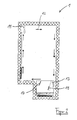
- FIG. 1 shows a climate cabinet 1 according to the invention, which is known per se in FIG Way thermally insulated housing 5 includes. At the front 7 is an access door provided, which is not shown in detail.
- the air-conditioned Interior is designated 3.
- a compressor-driven evaporator element 9 On the rear wall is a compressor-driven evaporator element 9, as it is known from conventional refrigerators.
- 11 denotes a fan or a fan, the air flow in the z. B. in Figures 2 and 3 Can generate direction 12.
- a moisture container 15 is provided, which is completed substantially airtight.
- the moisture container 15 is during operation liquid 21.
- the moisture container 15 is closed by tight closing flaps 17 and 19.
- the flaps 17, 19 are located on the respective boundary wall of the moisture container 15 and close the interior 3 of the Climate cabinet 1 against the interior of the moisture container 15 tightly.
- 13 refers to a blower that can generate an air flow, as z. B. in the bottom Part of Figure 3 is shown by arrows 14.
- Below the moisture container 15 is a heater 23 for heating the liquid 21 in the bottom area foamed up of the liquid container 15 in the heat insulation. 25 denotes a z. B. filtered by means of a carbon filter air access for the interior 3.
- an interior heating 27th provided, which serves to heat the interior.
- 29 denotes a condensation water drain
- the z. B. leads to a condensation gutter and condensation water, which has deposited on the evaporator 9, z. B. on an evaporation tray above a cooling compressor, not shown, leads to evaporation there respectively.
- a humidity meter in the interior of the 3 Climate cabinet 1, the z. B. formed by a hygrometer or Hygroclip can be.
- the climate chamber has a control of the humidity control z. B. in the form of a mechanical hygrostat on the z. B. behind a fan cover the blower 11 may be arranged.
- a temperature measuring device is provided.
- the moisture container 15 is designed as a unit that completely made of the Air conditioning cabinet 1 can be removed to z. B. cleaned or filled to become.
- the individual process steps are z. B. automatically by a microprocessor control causes the operation of the blower 11, 23 and the heaters 23, 27 depending on humidity and temperature.
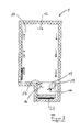
- FIG. 2 shows the normal operation of the climatic cabinet 1.
- the evaporator 9 is in operation, to cool air that is moved past it.
- the by the blower 11 caused air movement is shown in Figure 2 with arrows. Denote stronger arrows warm air, while thinner arrows indicate colder air schematically.
- the air passes the evaporator 9, it is cooled.
- the air cools the interior of the third and the inserted good.
- the blower 13 is out of operation and the flaps 17, 19 are closed. The circulating air therefore does not come with the moisture 21 in touch.
- the conventional Be measured using an appropriate thermometer can, the evaporator 9 is operated for cooling and the fan 11 for circulation.
- the microprocessor control sets the fan 13 in motion. By the air flow generated in this way open the flaps 19 and 17, so that the Air is passed through the moisture container 15 therethrough. She strokes over the Fluid surface of the liquid 21 away and is moistened there. On In this way, the humidity in the climate chamber 1 is adjustable. Should it be the In addition, sinking humidity may require the help of the heating element 23, the evaporation of the liquid 21 can be increased to the degree of humidification to further increase the air passing by on the surface.
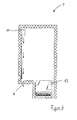
- the dehumidifying operation is initiated, which is shown schematically in Figure 4.
- the fan 13 is stopped, so that the flaps 17 and 19 go back to their rest position and the Complete the moisture container 15 from the interior 3 of the climatic chamber 1.
- the Blower 11 is also stopped to prevent the evaporator 9 collected moisture distributed in the interior. Settling at the evaporator 9 Moisture drips from the evaporator and is via the condensation water outlet 29 dissipated.
- the interior heating element 27 can additionally be operated become. In this way, the interior of the climatic chamber 1 heat is supplied and the duration of the refrigeration cycle of the evaporator 9 increases to the Keep the temperature at the desired low level. By the so strengthened Evaporator performance increases the precipitation of moisture at the evaporator and an additional effective dehumidifying mechanism occurs.
- the control of the climatic chamber 1 is set or programmed in this way, that a corresponding timing of the heaters 23, 27, the blower 11, 13 and of the evaporator 9 a desired narrow temperature or humidity range comply.
- the constant humidity in the interior 3 of the air conditioning cabinet 1 can by use appropriate materials z. B. for shelves and drawers increased become.
- the interior trim and air ducts can from these Consist of substances.
- the moisture container 15 can improve the humidifying substances included, which increase the moisture-emitting surface, z.
- Substances that have a stabilizing effect on the humidity can be used in the interior, z.
- propylene glycol for example, propylene glycol.
- a UV light source may be provided for Disinfection of the liquid 21 can be used.
- an indication of the degree of filling may be provided, too to be able to recognize from the outside whether sufficient liquid is present.
- the liquid container 15 is either removable as a whole to clean it and to be able to fill. Similarly, an automatic filling of a be provided separate storage tank, which is then carried out when the Level gauge too low degree of filling of the liquid container 15th displays. In addition or only in the storage tank can then already described above UV light source may be provided to ensure disinfection.
- liquid container 15 can also have an external filtered Fixed water connection to be filled automatically.
- climatic cabinet Inside the climatic cabinet are storage areas tailored to the purpose of use provided, such.
- these elements are made of wood, in particular Cedar wood designed in addition to compensate for humidity fluctuations Act.
- the climatic cabinet 1 with an insulating glass door be provided, which is specially coated UV-inhibiting.
- the interior of the climatic chamber can be illuminated by means of light emitting diodes, which no Give UV light to the inserted good in addition to UV irradiation protect.
Landscapes
- Engineering & Computer Science (AREA)
- Chemical & Material Sciences (AREA)
- Combustion & Propulsion (AREA)
- Physics & Mathematics (AREA)
- Mechanical Engineering (AREA)
- Thermal Sciences (AREA)
- General Engineering & Computer Science (AREA)
- Cold Air Circulating Systems And Constructional Details In Refrigerators (AREA)
- Central Air Conditioning (AREA)
- Devices That Are Associated With Refrigeration Equipment (AREA)
Applications Claiming Priority (2)
| Application Number | Priority Date | Filing Date | Title |
|---|---|---|---|
| DE200410017855 DE102004017855A1 (de) | 2004-04-13 | 2004-04-13 | Klimaschrank, Humidor und Verfahren zum Klimatisieren eines Klimaraumes |
| DE102004017855 | 2004-04-13 |
Publications (2)
| Publication Number | Publication Date |
|---|---|
| EP1586824A2 true EP1586824A2 (fr) | 2005-10-19 |
| EP1586824A3 EP1586824A3 (fr) | 2007-10-31 |
Family
ID=34935130
Family Applications (1)
| Application Number | Title | Priority Date | Filing Date |
|---|---|---|---|
| EP05008102A Withdrawn EP1586824A3 (fr) | 2004-04-13 | 2005-04-13 | Armoire de climatisation, humidificateur et méthode de climatisation d'une pièce |
Country Status (2)
| Country | Link |
|---|---|
| EP (1) | EP1586824A3 (fr) |
| DE (1) | DE102004017855A1 (fr) |
Cited By (11)
| Publication number | Priority date | Publication date | Assignee | Title |
|---|---|---|---|---|
| EP1857022A1 (fr) * | 2006-05-11 | 2007-11-21 | Caverion GmbH | Vitrine destinée à loger des objets |
| CN101191646A (zh) * | 2006-11-30 | 2008-06-04 | 新疆绿色使者空气环境技术有限公司 | 蒸发制冷冷水机组 |
| WO2011061065A3 (fr) * | 2009-11-17 | 2011-07-14 | BSH Bosch und Siemens Hausgeräte GmbH | Appareil frigorifique comprenant un compartiment de stockage pouvant être fermé hermétiquement au moyen d'un dispositif de ventilation mécanique |
| US8225620B2 (en) * | 2008-02-26 | 2012-07-24 | Liebherr-Hausgerate Lienz Gmbh | Refrigerator unit and/or freezer unit |
| EP1959215A3 (fr) * | 2007-02-16 | 2012-07-25 | Whirlpool Corporation | Procédé pour le contrôle de l'humidité dans un réfrigérateur domestique, et réfrigérateur adapté pour réaliser un tel procédé |
| US20130014522A1 (en) * | 2011-07-12 | 2013-01-17 | A.P. Moller - Maersk A/S | Humidity control in a refrigerated transport container with an intermittently operated compressor |
| EP2249108A3 (fr) * | 2009-04-28 | 2014-08-06 | Samsung Electronics Co., Ltd. | Ensemble de garde de porte et réfrigérateur doté de celui-ci |
| CN109990529A (zh) * | 2017-12-29 | 2019-07-09 | 青岛海尔股份有限公司 | 冰箱 |
| CN113532019A (zh) * | 2020-04-21 | 2021-10-22 | 青岛海尔特种电冰柜有限公司 | 一种酒柜 |
| CN119594645A (zh) * | 2025-01-16 | 2025-03-11 | 合肥华凌股份有限公司 | 加湿组件及制冷设备 |
| FI131374B1 (en) * | 2023-02-20 | 2025-03-14 | Betolar Oyj | Climate cabinet and procedure |
Families Citing this family (2)
| Publication number | Priority date | Publication date | Assignee | Title |
|---|---|---|---|---|
| WO2013007627A1 (fr) * | 2011-07-12 | 2013-01-17 | A.P. Møller - Mærsk A/S | Régulation de l'humidité dans un conteneur de transport réfrigéré comprenant un compresseur actionné par intermittence |
| EP2546084A1 (fr) * | 2011-07-12 | 2013-01-16 | A.P. Møller - Mærsk A/S | Contrôle de l'humidité dans un conteneur de transport réfrigéré doté d'un compresseur à fonctionnement intermittent |
Citations (2)
| Publication number | Priority date | Publication date | Assignee | Title |
|---|---|---|---|---|
| US6122918A (en) | 1999-07-09 | 2000-09-26 | Odin Design Limited | Storage cabinet for cigars |
| DE10164321C1 (de) | 2001-12-28 | 2003-07-10 | Carsten Schroeter | Vorrichtung zur Klimatisierung eines insbesondere kleinen Raumes und Klimaschrank mit einer derartigen Vorrichtung |
Family Cites Families (5)
| Publication number | Priority date | Publication date | Assignee | Title |
|---|---|---|---|---|
| US3424231A (en) * | 1967-03-23 | 1969-01-28 | Andrew Truhan | Environmental chamber |
| DE1949001C3 (de) * | 1969-09-27 | 1975-08-21 | Ernst Voetsch Kaelte- Und Klimatechnik Kg, 7462 Frommern | Verfahren und Einrichtung zur Regelung der Luftfeuchte in einer Pflanzenwuchskammer |
| US5007242A (en) * | 1988-09-30 | 1991-04-16 | Snow Brand Milk Products Co., Ltd. | Thermoelectric humidifier and display case provided with such humidifier |
| DE20016948U1 (de) * | 2000-09-30 | 2001-01-04 | Schneider, Dietmar, 74847 Obrigheim | Vorrichtung zur Aufbewahrung von Tabak und/oder Tabakartikeln |
| FR2845250B1 (fr) * | 2002-10-07 | 2005-01-07 | Humid Oc | Procede et cave de stockage, conservation et maturation de cigares a renouvellement d'air |
-
2004
- 2004-04-13 DE DE200410017855 patent/DE102004017855A1/de not_active Withdrawn
-
2005
- 2005-04-13 EP EP05008102A patent/EP1586824A3/fr not_active Withdrawn
Patent Citations (2)
| Publication number | Priority date | Publication date | Assignee | Title |
|---|---|---|---|---|
| US6122918A (en) | 1999-07-09 | 2000-09-26 | Odin Design Limited | Storage cabinet for cigars |
| DE10164321C1 (de) | 2001-12-28 | 2003-07-10 | Carsten Schroeter | Vorrichtung zur Klimatisierung eines insbesondere kleinen Raumes und Klimaschrank mit einer derartigen Vorrichtung |
Cited By (13)
| Publication number | Priority date | Publication date | Assignee | Title |
|---|---|---|---|---|
| EP1857022A1 (fr) * | 2006-05-11 | 2007-11-21 | Caverion GmbH | Vitrine destinée à loger des objets |
| CN101191646A (zh) * | 2006-11-30 | 2008-06-04 | 新疆绿色使者空气环境技术有限公司 | 蒸发制冷冷水机组 |
| EP1959215A3 (fr) * | 2007-02-16 | 2012-07-25 | Whirlpool Corporation | Procédé pour le contrôle de l'humidité dans un réfrigérateur domestique, et réfrigérateur adapté pour réaliser un tel procédé |
| US8225620B2 (en) * | 2008-02-26 | 2012-07-24 | Liebherr-Hausgerate Lienz Gmbh | Refrigerator unit and/or freezer unit |
| EP2249108A3 (fr) * | 2009-04-28 | 2014-08-06 | Samsung Electronics Co., Ltd. | Ensemble de garde de porte et réfrigérateur doté de celui-ci |
| WO2011061065A3 (fr) * | 2009-11-17 | 2011-07-14 | BSH Bosch und Siemens Hausgeräte GmbH | Appareil frigorifique comprenant un compartiment de stockage pouvant être fermé hermétiquement au moyen d'un dispositif de ventilation mécanique |
| US20130014522A1 (en) * | 2011-07-12 | 2013-01-17 | A.P. Moller - Maersk A/S | Humidity control in a refrigerated transport container with an intermittently operated compressor |
| CN109990529A (zh) * | 2017-12-29 | 2019-07-09 | 青岛海尔股份有限公司 | 冰箱 |
| CN109990529B (zh) * | 2017-12-29 | 2020-09-29 | 青岛海尔股份有限公司 | 冰箱 |
| CN113532019A (zh) * | 2020-04-21 | 2021-10-22 | 青岛海尔特种电冰柜有限公司 | 一种酒柜 |
| FI131374B1 (en) * | 2023-02-20 | 2025-03-14 | Betolar Oyj | Climate cabinet and procedure |
| CN119594645A (zh) * | 2025-01-16 | 2025-03-11 | 合肥华凌股份有限公司 | 加湿组件及制冷设备 |
| CN119594645B (zh) * | 2025-01-16 | 2026-03-24 | 合肥华凌股份有限公司 | 加湿组件及制冷设备 |
Also Published As
| Publication number | Publication date |
|---|---|
| EP1586824A3 (fr) | 2007-10-31 |
| DE102004017855A1 (de) | 2005-11-10 |
Similar Documents
| Publication | Publication Date | Title |
|---|---|---|
| EP2096388B1 (fr) | Appareil de réfrigération et/ou de refroidissement | |
| EP1586824A2 (fr) | Armoire de climatisation, humidificateur et méthode de climatisation d'une pièce | |
| EP0243536B1 (fr) | Appareil pour purifier et/ou pour humidifier et sécher des gaz, en particulier l'air | |
| EP0231789A2 (fr) | Dispositif de climatisation d'un jardin d'hiver | |
| DE102017212412A1 (de) | Befeuchter und Verfahren zur Konditionierung von Luft | |
| EP1554526B1 (fr) | Systeme d'echange d'air destine a la ventilation au moins d'une piece d'un batiment | |
| DE10164321C1 (de) | Vorrichtung zur Klimatisierung eines insbesondere kleinen Raumes und Klimaschrank mit einer derartigen Vorrichtung | |
| DE102020205749A1 (de) | Haushalts-Kühlgerät und Verfahren zum Belüften eines Kühlfachbehälters | |
| DE102005022934A1 (de) | Schrank zum kontrollierten Aufziehen von Pflanzen und zur Erreichung gleichbleibender pflanzlicher Geschmacksqualitäten | |
| DE1949001A1 (de) | Verfahren und Einrichtung zur Regelung des Klimas in einer Pflanzenwuchskammer | |
| EP2642224B1 (fr) | Appareil de réfrigération et/ou de congélation | |
| EP0076512B1 (fr) | Dispositif de conservation pour pain et pour de telles denrées alimentaires | |
| DE19546493A1 (de) | Klimasteuerung für Kühltheken | |
| EP0913199B1 (fr) | Dispositif pour humidifier l'espace utile d'un incubateur | |
| DE60312926T2 (de) | Gewächshaus kleinerer Baugrösse mit einer kontrollierten internen Umgebung | |
| DE3212250A1 (de) | Einrichtung zum erwaermen von back- oder teigwaren | |
| DE29517940U1 (de) | Transport- und Klimabehälter für Speisen | |
| DE2546494A1 (de) | Verfahren zur langzeitkonservierung von getreide | |
| DE102008051748B4 (de) | Verfahren zur Entfeuchtung der Luft im Innenraum eines Gerätes | |
| DE4407382A1 (de) | Kühlvorrichtung | |
| DE102021103093A1 (de) | Kühlmöbel und Verfahren zu dessen Steuerung, Computerprogrammprodukt sowie Steuereinheit | |
| DE102004045255B4 (de) | Humidor | |
| DE2940242C2 (de) | Frischhalteeinrichtung für Brot u.dgl. Lebensmittel | |
| AT514695B1 (de) | Vorrichtung und Verfahren zum Trocknen von Trocknungsgut | |
| CH254872A (de) | Holztrocknungsanlage. |
Legal Events
| Date | Code | Title | Description |
|---|---|---|---|
| PUAI | Public reference made under article 153(3) epc to a published international application that has entered the european phase |
Free format text: ORIGINAL CODE: 0009012 |
|
| AK | Designated contracting states |
Kind code of ref document: A2 Designated state(s): AT BE BG CH CY CZ DE DK EE ES FI FR GB GR HU IE IS IT LI LT LU MC NL PL PT RO SE SI SK TR |
|
| AX | Request for extension of the european patent |
Extension state: AL BA HR LV MK YU |
|
| RIN1 | Information on inventor provided before grant (corrected) |
Inventor name: OBMASCHER, UMBERTO Inventor name: PRENTNER, ANDREAS |
|
| PUAL | Search report despatched |
Free format text: ORIGINAL CODE: 0009013 |
|
| AK | Designated contracting states |
Kind code of ref document: A3 Designated state(s): AT BE BG CH CY CZ DE DK EE ES FI FR GB GR HU IE IS IT LI LT LU MC NL PL PT RO SE SI SK TR |
|
| AX | Request for extension of the european patent |
Extension state: AL BA HR LV MK YU |
|
| 17P | Request for examination filed |
Effective date: 20071221 |
|
| AKX | Designation fees paid |
Designated state(s): AT DE ES FR IT |
|
| 17Q | First examination report despatched |
Effective date: 20110617 |
|
| STAA | Information on the status of an ep patent application or granted ep patent |
Free format text: STATUS: THE APPLICATION IS DEEMED TO BE WITHDRAWN |
|
| 18D | Application deemed to be withdrawn |
Effective date: 20160203 |